A GENERIC FRAMEWORK FOR FILTERING IN SUBBAND-DOMAIN Abdellatif Benjelloun Touimi France Télécom R&D - DIH/DIPS 2, avenue Pierre Marzin, F-22307 - Lannion Cedex, France.
[email protected]
ABSTRACT Subband domain filtering is a beneficial method that can be advantageously used in many applications. This paper discusses a method of generating filters in subband domain of any critically sampled perfect reconstruction filter bank, equivalent to any rational (FIR or IIR) timedomain filter. As example, implementation for the particular case of MDCT filter bank is given.
1. INTRODUCTION
T
RANSFORM and subband coding have known a great expansion in multimedia signals compression. It is the basis of lot of standardised and popular algorithms of perceptual audio coding [1]. Specifically, MPEG-1 Layer I and II audio standards are based on filter bank with a pseudo-QMF structure. The MDCT transform becomes the mainstay of the most modern and efficient audio coders: MPEG-4 AAC and Twin VQ, Dolby AC-3, … In video and image compression, the DCT transform remains the core of all coding standards (MPEG, JPEG, H.261, H.263). Although developed independently, all these time-frequency mappings can be described by unified approaches and from various viewpoints: cosine modulated filter banks, lapped orthogonal transforms or more generally by critically sampled filter banks theory [2], [3]. Several audio processing are based on filtering operations. Sound spatialization and reverberation is an example that enables to generate the illusion of a natural sound environment. Filtering of audio signals initially represented in compressed domain needs fully decoding operation, filtering in time-domain, and re-encoding. An alternative to this heavy computational method consists in manipulating directly subbands signals after unpacking and dequantization operations. However, using this method is not so straightforward. Any processing of subbands signals introduces a modification of the aliasing components resulting from using non-perfect filters before the decimation in the analysis filter bank. If this modification is not adequately performed, aliasing cancellation will not be assured by the synthesis filter bank, causing hence audible artefacts in the reconstructed signal.
To solve this problem, two types of solutions have been developed in the literature. The first one is approximate and restrictive. Hence to make filtering for audio effects (reverberation, chorus…) in MPEG-1 subbands signals, the author in [4] suggests to constrain subband filters to have equal amplitudes close the subband boundary. In [5] no special processing is done, but propose only to profit from the structure of MPEG-1 filter bank to have limited aliasing errors which can then be perceptually masked. The second approach attempts to derive a formulation of subband filters in such a way signals resulting from timeand-subband domain filtering are exactly equivalent. In [6], a solution is given for DCT domain FIR-filtering. A combined operator matrix equivalent to the succession of the inverse DCT, the linear convolution and the DCT transform is pre-computed. In [7], a more efficient method is developed based on the convolution-multiplication property of the DCT transform introduced in [8]. The framework given in [9] and [10] can be considered as the state of the art of subband domain FIR-filtering for perfect reconstruction critically sampled filter banks. The proposed generation method of the subband filters is essentially based on the convolution matrix representation of analysis/synthesis filter banks and the time-domain filter. Therefore, this method is restricted to the case of FIR-filtering. In this paper, we present a new solution that can be applied to any rational filter (FIR or IIR). The extension of subband-domain filtering to IIR filters will provide doing new processing in subband-domain like audio reverberation by all-pass filters [14]. It will make also possible to take advantage of the low complexity of this filtering type, in some implementation cases, compared to FIR-filtering. As an application example, we consider the case of IIR-filtering in subbands audio signals of MDCT filter bank.
2. SUBBAND DOMAIN FILTERING 2.1 Problem definition and representation Consider an M-band critically sampled perfect reconstruction filter bank given by the analysis and synthesis filters, H k ( z ) and Fk ( z ) , 0 ≤ k ≤ M − 1 , respectively. Let S ( z ) be a transfer function of an
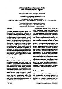
arbitrary rational filter. The problem of subband domain filtering consist in determining the filters to apply to subbands signals such that the signal obtained after synthesis will be equivalent to that resulting from timedomain filtering, by S ( z ) , the initially synthesised signal. This problem is clearly defined by figure 1 schemes [9]. X( z)
Analysis Filter Bank
Synthesis Filter Bank
Time-Domain Filtering
Yt ( z )
SB-Domain Filtering
Analysis Filter Bank
Synthesis Filter Bank
For the same purpose announced above, we consider the block representation of the time-domain scalar filter S ( z )
given by the transfer matrix P ( z ) . This matrix has a pseudo-circulant structure; its expression can be directly obtained from the polyphase components, Pk ( z ) ,
0 ≤ k ≤ M − 1 , of the transfer function S ( z ) [11]:
(a) X( z)
an integer related to the analysis/synthesis filters length, L , by: L = ( K + 1) M . (2)
P0 ( z) −1 z PM−1 ( z) P( z) = z−1 P ( z) 1
Ysb ( z )
M
(b) Fig. 1: Blocks diagram of (a) time-domain filtering (b) subband-domain filtering. As subbands signals are related by aliasing components, filtering operation should keep this relation so that they can be cancelled when synthesising. For this purpose, the subband filtering operation is represented by a filters matrix, Psb ( z ) , so the output signal in subband n will result from a combination of all subbands signals filtered by Psb,nk ( z ) , 0 ≤ k ≤ M − 1 , (figure 2). X(z)
H0 ( z )
↓M
H1 ( z )
↓M
U0 ( z ) U1 ( z )
↓M
V1 ( z )
Psb ( z)
. . . HM −1 ( z )
V0 ( z )
UM−1 ( z)
F1 ( z )
VM-1 ( z )
X( z )
↑M
FM −1 ( z )
−1
z −1
. . .
Ysb ( z )
↓M
. . .
R ( z ) , respectively [2]. As the filter bank is supposed to be perfect reconstruction, these matrices verify [2]: R ( z ) E ( z ) = z−K IM , (1)
where I M denotes the M × M identity matrix and K is
Yt ( z )
Identity Operator
↓M
z M −1
↑M
E( z) . . .
↑M
R(z)
. . .
Analysis Filter Bank
z −1
z −1
−1
−1
z
z −1
↑M
↓M
Synthesis Filter Bank
z
z −1
↓M
↑M
↓M
↑M
. . .
P( z)
↓M
. . .
↑M
z −1 z −1 z −1
Yt ( z )
Block Representation of the filter S ( z )
(a)
Fig. 2: Subband-domain filtering. The representation given in figure 2 is not adequate to find a mathematical solution for the problem of subbanddomain filtering. Using z-transform matrices to represent problem blocks described in figure 1 will make the resolution possible and for any type of filters as it will be discussed later. With this aim in view, let us consider the polyphase representation of the filter bank given by the analysis and synthesis polyphase matrices, E ( z ) and
z−1 PM−1 ( z)
serial-to-parallel converters. It is easy to see that cascading these two blocks is equivalent to an identity operator.
z
↑M
M
matrix P ( z ) by a succession of parallel-to-serial and
z −1
F0 ( z )
O L
PM−1 ( z) PM−2 ( z) (3) P1 ( z) P0 ( z)
L O
P1 ( z)
Using these representations we can replace schemes of figure 1 by those of figure 3. In figure 3a, the polyphase synthesis matrix R ( z ) is connected to the block filter
X( z) ↑M
L O
P1 ( z) P0 ( z)
X( z ) X( z) z −1 z
−1
z −1
Ysb ( z )
↓M ↓M
. . .
↑M
. E( z) . .
Psb
. ( z) . .
↓M
Analysis Filter Bank
↑M
R ( z)
. . .
↑M
Subband Filtering
z −1 z −1 z −1
Ysb ( z )
Synthesis Filter Bank
(b) Fig. 3: Representation by multirate blocks of filtering schemes in (a) time-domain (b) subband-domain.
2.2 Subband filters matrix formulations Based on figure 3 representations, it becomes obvious to express the outputs of time- and subband-domain filtering: Yt ( z ) = P ( z ) R ( z ) E ( z ) X ( z ) , (4)
Ysb ( z ) = R ( z ) Psb ( z ) E ( z ) X ( z ) ,
(5)
X ( z ) = X 0 ( z ) X M −1 ( z ) L X1 ( z ) , T
where functions
Xk ( z ) ,
with
0 ≤ k ≤ M − 1 , are the polyphase
components of X ( z ) , and
Relation (28) in the appendix gives the expression of two product filters polyphase components. By comparing equations (12), for fixed n , to (28) it can be deduced that functions Q nk ( z ) , 0 ≤ k ≤ M − 1 , are the polyphase components of the product filter H n ( z ) × S ( z ) .
In other hand, the elements of the matrix W ( z ) can be written as: M −1
Wnk ( z ) = ∑ Q nl ( z ) R lk ( z ) , 0 ≤ n, k ≤ M − 1 . (13) l =0
By replacing the type-2 polyphase components, R lk ( z ) ,
Yt ( z ) = Yt, M-1 ( z ) L Yt,1 ( z ) Yt,0 ( z ) , T
0 ≤ l ≤ M − 1 , of the synthesis filter Fk ( z ) by their
Ysb ( z ) = Ysb, M-1 ( z ) L Ysb,1 ( z ) Ysb,0 ( z ) . T
Relation (1) shows that E ( z ) and R ( z ) are non-
corresponding type-1 polyphase components, R ′lk ( z ) , Eq. (13) becomes: M −1
singular matrices and: R −1 ( z ) = z K E ( z ) .
(6)
Wnk ( z ) = ∑ Q n l ( z ) R ′( M -1-l )k ( z ) , 0 ≤ n, k ≤ M − 1 . (14)
Hence, by equalising expressions of Yt ( z ) and Ysb ( z ) ,
The comparison of this expression to Eq. (28) shows that
and using (6), it can be deduced the transfer matrix of the subband domain-filtering: Psb ( z ) = z K E ( z ) P ( z ) R ( z ) . (7)
the function
Property: Subband filters can be expressed directly from the analysis/synthesis filters and the scalar timedomain filter as:
Psb,nk ( z ) = z
L −1
H n ( z ) S ( z ) Fk ( z )
↓M
, 0 ≤ n, k ≤ M − 1 , (8)
where ↓ M stands for factor M decimation. Or equivalently, by using a matrix form, as: Psb ( z ) = z L−1h ( z ) S ( z ) f ( z ) ,
(9)
↓M
where and
T
For an arbitrary filter, A ( z ) , its l th type-1 polyphase
component, A l ( z ) , can be expressed as [2]:
A l ( z ) = z l A ( z )
↓M
, 0 ≤ l ≤ M −1 .
Hence, it can be concluded that: Wnk ( z ) = z M −1 H n ( z ) S ( z ) Fk ( z )
↓M
(15)
, 0 ≤ n, k ≤ M − 1 .(16)
Finally, the relation (8) can be deduced by introducing the advance z K in Eq. (16), with z K = z KM , and by
The property given by equation (8) shows that the subband filters Psb,nk ( z ) , 0 ≤ k ≤ M − 1 , which contribute
Proof: Let Q ( z ) and W ( z ) matrices defined by: (10) (11)
Using the structure of P ( z ) , given by Eq. (3), we can
express the elements of the matrix Q ( z ) as:
k M −1 −1 Qnk ( z ) = ∑Enl ( z ) P( k −l) ( z ) + ∑ Enl ( z ) P( M +k −l ) ( z ) z ,0 ≤ k ≤ M − 2, (12) l =0 l =k +1 M −1 Q ( z ) = ∑ Enl ( z ) P( M −1−l) ( z ), n,( M −1) l =0
where 0 ≤ n ≤ M − 1 .
th
using the relation (2).
f ( z ) = F0 ( z ) F1 ( z ) K FM −1 ( z ) .
W( z) = Q( z)R( z) .
Wnk ( z ) corresponds to the ( M − 1) polyphase component of the product filter H n ( z ) S ( z ) × Fk ( z ) .
↓M
h ( z ) = H 0 ( z ) H1 ( z ) L H M −1 ( z ) ,
Q( z ) = E( z ) P ( z ) ,
l =0
to the output signal in subband n , are obtained by convoluting the time-domain filter, S ( z ) , and the analysis
filter H n ( z ) by all synthesis filters, before decimation
operation. The advance z L −1 serves to remove the delay introduced by the analysis and synthesis filters. Hence, only the subband filters Psb,nk ( z ) such that the subbands n and k are sufficiently recovering will have a significant energy. This means that when implementing subband filtering by the matrix Psb ( z ) , each line n can be reduced to the following form:
0
LP
sb,n( n−δ ) mod M
( z)
LP
sb,nn
( z)
LP
sb,n( n+δ ) mod M
( z)
L 0 ,(17)
where δ denotes the number of bands which recover significantly in one side with the subband n , and ’mod’ denotes modulo operator. Note that the matrix form, given by (9), can be considered as the equivalent expression, in z-transform domain, to the one developed in [9] based on convolution matrices.
2.3 Generation and implementation of subband IIR-filtering The case of FIR-filtering has been studied in [9]. The author has used the overlap-add method of block convolution to implement subband filters. In this paragraph, we consider S ( z ) as an IIR filter. Method of decomposing this filter type is given in [15]; its polyphase components has the form: N ( z) , 0 ≤ k ≤ M −1 , (18) Pk ( z ) = k D( z) where D ( z ) is a common denominator of all components. The subband filters matrix can then be written as: 1 Psb ( z ) = N sb ( z ) , D( z)
(19)
where N sb ( z ) = z K E ( z ) N ( z ) R ( z ) , with N ( z ) is FIRfilter transfer matrix containing numerators of P ( z ) .
This expression suggests implementing subband filters in canonic direct form [12] and factorising the feedback loops. Hence, if: V ( z ) = Psb ( z ) U ( z ) , (20) we denote
G(z) =
1 U(z) , D( z)
(21)
it yields
V ( z ) = N sb ( z ) G ( z ) .
(22)
Ld −1
Lnk −1
j =1
j =0
If D ( z ) = 1 − ∑ b [ j ] z − j and N sb,nk ( z ) =
∑ a [ j] z nk
−j
,
0 ≤ n, k ≤ M − 1 , the implementation equations can be easily derived: L d −1 g n [i ] = u n [ i ] + ∑ b [ j ] g n [ i − j ], j =1 Lnk −1 v [i ] = ∑ ∑ a n k [ j ] g k [i − j ] , n k∈ℑ n j = 0
(23)
where 0 ≤ n ≤ M − 1 and ℑn is the set of subband filters index with significant energy for output signal of subband n.
3. EXAMPLE: FILTERING IN MDCT FILTER BANK SUBBANDS Let us consider the MDCT transform given by its M × 2M transform matrix T as [3]:
[ T]m,l =
2 M + 1 1 π h [l ] cos l + m + , (24) M 2 2M
where 0 ≤ m ≤ M − 1 , 0 ≤ l ≤ 2M − 1 and 1 π h [l ] = sin l + . 2 2 M
(25)
This transform initially developed by Princen [13], as Time Domain Aliasing Concellation (TDAC) filter bank, is particular case of Lapped Orthogonal Transforms (LOT) [3]. It can be also seen as cosine-modulated filter bank with analysis and synthesis filters of length L = 2M , and hence K = 1 . Polyphase representation of this filter bank can be given by considering the partition T = [ T0 T1 ] , where T0 and T1 are M × M matrices. Hence, the analysis and synthesis polyphase matrices are expressed as [3]: E ( z ) = T1J M + T0 J M z −1 , (26) T T −1 R ( z ) = J M T0 + J M T1 z ,
0 K 1 where J M = M N M is the M × M counter identity 1 L 0 matrix. Equations (7) and (26) allows determining filtering matrix in TDAC filter bank subband-domain for any filter. However the advance z in Eq. (7) produces non-causal filtering matrix. To deal with this problem we replace this equation by: Psb ( z ) = E ( z ) P ( z ) R ( z ) (27) As an example, we have implemented binaural synthesis for sound spatialization, in subband domain of "TDAC du CNET" coder. This wideband speech and music coder use MDCT transform with M = 320 , details of quantization and coding are described in references [16] and [17]. The head-related transfer functions (HRTF) are modelled in the time-domain by 12-order IIR filters followed by a delay corresponding to the interaural time delay (ITD) [18]. After generating the equivalent subband filters, the implementation is performed as described in section 2.3. Informal listening tests have shown that taking δ = 2 is sufficient to have a complete transparency compared to time-domain processing.
4. CONCLUSION In this paper, we have presented a new solution to the problem of subband-domain filtering. This solution was developed based on polyphase representation of the filter bank and block version of the time-domain filter. It can be applied for any type of filters (FIR or IIR) and for any filter bank satisfying the perfect reconstruction property. The advantages given by processing in compresseddomain encourage using this method in many applications. For particular applications in audio and image, filter banks have specific characteristics (cosine modulated filter banks, MDCT, DCT…). Furthermore, considered filters are not so arbitrary, they have some particular properties (symmetric FIR, all-pass IIR...). Future works should adapt this solution to each particular case in order to have efficient implementation and hence more low computational complexity.
APPENDIX Let S1 ( z ) and S2 ( z ) two transfer functions and P1, k ( z ) ,
P2, k ( z ) ,
0 ≤ k ≤ M −1 ,
their
corresponding
type-1
polyphase components, respectively. Consider Sc ( z ) the
product of S1 ( z ) and S2 ( z ) . By writing these filters as function of their polyphase components and developing the product, it can be deduced the following expressions of the polyphase components of Sc ( z ) : k M −1 −1 Pc,k ( z ) = ∑P1,l ( z ) P2,( k−l ) ( z) + ∑ P1,l ( z ) P2,( M +k−l ) ( z) z , 0 ≤ k ≤ M − 2, (28) l =0 l =k +1 M −1 P ( z) = ∑P1,l ( z ) P2,( M−1−l) ( z ). c,( M −1) l =0
REFERENCES [1]
M. Bosi, "Filter Banks in perceptual Audio Coding," AES 17th Conference on high-quality Audio Coding, September 2-5, 1999, Florence, Italy.
[2]
P. P. Vaidyanathan, Multirate Systems and Filter Banks. Prentice Hall, Englewood Cliffs, NJ, 1993.
[3]
H. S. Malvar, Signal Processing with Lapped Transforms. Artech House, Inc. 1992.
[4]
M. A. Broadhead, and C. B. Owen, "Direct Manipulation of MPEG Compressed Digital Audio," ACM Multimedia Conference, San Francisco, 1995.
[5]
S. N. Levine, "Effects Processing on Audio Subband Data," ICMC Proceeding, 1996.
[6]
J. B. Lee, and B. G. Lee, "Transform Domain Filtering Based on Pipelining Structure," IEEE Trans. on Signal Processing, vol. 40, no. 8, August 1992.
[7]
R. Kresch, and N. Merhav, "Fast DCT Domain Filtering Using the DCT and the DST," IEEE Trans. on Image Processing, vol. 8, no. 6, June 1999.
[8]
S. A. Martucci, "Symmetric Convolution and the Discrete Sine and Cosine Transforms," IEEE Trans. on Signal Processing, vol. 42, vol. 5, May 1994.
[9]
C. A. Lanciani, and R. W. Schafer, "Subband-Domain Filtering of MPEG Audio Signals," IEEE Int. Conf. on Acoust., Speech, Signal Proc., 1999, Arizona , USA.
[10] C. A. Lanciani, Compressed-Domain Processing of MPEG Audio Signals. Ph.D. thesis, Georgia Institute of Technology, 1999. [11] P. P. Vaidyanathan, and S. K. Mitra, "Polyphase Networks, Block Digital Filtering, LPTV Systems, and Alias-Free QMF Banks: A Unified Approach Based on Pseudocirculants," IEEE Trans. on ASSP, vol. 36, no. 3, March 1988. [12] A. V. Oppenheim, R. W. Shafer, and J. R. Buck, DiscreteTime Signal Processing. Prentice-Hall, 1999. [13] J. P. Princen, and A. B. Bradley, "Analysis/Synthesis filter Bank Design Based on Time Domain Aliasing Cancellation," IEEE Trans. on ASSP, vol. ASSP-34, no. 5, October 1986. [14] W. G. Gardner, "Reverberation Algorithms," Applications of Digital Signal Processing to Audio and Acoustics. Edited by M. Kahrs and K. Brandenburg, Kluwer Academic Publishers, 1998. [15] M. Bellanger, Digital Processing of Signals. Wiley, 1984. [16] P. Combescure and al., "A 16, 24, 32kbits/s Wideband Speech Codec Based on ATCELP," IEEE Int. Conf. on Acoust., Speech, Signal Proc., 1999, Arizona , USA. [17] Y. Mahieux, and J. P. Petit, "High- Quality Audio Transform Coding at 64 kbps," IEEE Trans. on Comm., vol. 42, no. 11, November 1994. [18] J.-M. Jot, V. Larcher and O. Warusfel, "Digital Signal Processing Issues in the Context of Binaural and Transaural Stereophony," AES 98th Convention, February 25-28, 1995, Paris.