Associate Technical Fellow ... applications in surveillance, robotic vision, automotive rear- ... degree while the other one is full frame fisheye lens with 180.
International Journal of Computer Applications (0975 – 8887) Volume 51– No.10, August 2012
A Generic Non-Linear Method for Fisheye Correction Pranali Dhane
Krishnan Kutty
Sachin Bangadkar
Research Associate KPIT Cummins Infosystems Ltd., Pune, India
Associate Technical Fellow KPIT Cummins Infosystems Ltd., Pune, India
Research Associate KPIT Cummins Infosystems Ltd., Pune, India
ABSTRACT With rapid advances in the field of vision based systems and ever increasing applications that they foster to; it brings along many challenges both in terms of algorithm design and associated hardware. One such widely used gadget is the fisheye camera that is used in myriad of applications in various fields owing to their wide Field of View. However, these lenses introduce distortions when any real-world object gets mapped on to the image plane. The amount of distortion in fish eye images increases while moving radially outward from the image centre. Therefore, the amount of correction to be applied should also vary accordingly based on the pixel location. This paper presents a fast and real-time implementable technique for fisheye correction. The proposed method uses non-linear radial stretching and scaling down of pixels thereafter; both in X and Y dimensions for correction. For real-time implementation of the proposed algorithm, we propose the use of inverse mapping matrix. This enables transformation of computationally extensive equations used for correction into a simple look-up table that can easily be implemented on a FPGA platform.
General Terms Image Processing, Fisheye Images
Keywords Fisheye Distortion, Field of View (FOV), radial correction, mapping matrix
1. INTRODUCTION Fisheye cameras are finding increasing number of applications in surveillance, robotic vision, automotive rearview imaging systems etc. because of their wide angle properties. There are broadly two types of fisheye lens; one is a circular fisheye lens whose vertical angle of view is 180 degree while the other one is full frame fisheye lens with 180 degree diagonal angle of view [9]. However, while fisheye lenses provide very large wide-angle views (theoretically the entire frontal hemispheric view of 180°) the images produced suffer from severe distortion since the hemispherical scene gets projected onto a flat surface [7]. There are two types of these distortions, radial distortion and tangential distortion. Tangential distortion is usually insignificant and is not considered while correcting the distortions. The effect of radial distortion is that straight lines/objects in the real world are distorted into curves and points are moved in radial direction from their correct position [2][3].
These distortions continue to increase as we move away from the centre of the fisheye image. Perceiving these distorted views can be both unusual and confusing to the viewer. It is therefore desirable to correct fisheye images into their approximately rectilinear versions before presenting to the end viewer [8]. Michal Kedzierski et. al. presented a fisheye correction method based on differential geometry and arc curvature in every segment of input image [4]. Brauer-Burchardt, C. et. al. proposed the fisheye correction algorithm based on circle fitting. This method only requires extraction of distorted image points from straight lines in the 3D scene [5]. Different models for fisheye distortion correction viz. polynomial and non-polynomial models have been studied in detail in literature. The problem with polynomial models is that there is no analytical method to invert them, i.e. there is no generic method to invert a forward model to its inverse for use in correction of radial distortion. This leads to the vacant pixels in the corrected image. On the other hand, the nonpolynomial models such as perspective model is based on the calculation of apparent focal length of fisheye camera which does not necessarily equate with the actual focal length of the fish-eye camera[1][6]. In this paper, we propose a method for correcting fish eye distortion using a non-linear radial stretching technique. This is followed by correction in both X and Y direction for removing distortions. In order to implement this proposed technique in real-time, we also introduce the concept of inverse mapping matrix. The final output is a simple look-up table that maps every pixel in the output fish eye corrected image to a corresponding pixel in the input uncorrected image. The rest of the paper is organized as follows. We explain our approach for fisheye correction in Section 2. In Section 3, we describe calculation of mapping matrix. In Section 4 we characterize the performance of our proposed approach by comparing the curvature of known landmark regions in the original and corrected images. This is followed by conclusion and discussions in Section 5.
2. FISHEYE IMAGE CORRECTION Typical fish eye lenses have a large field of view (FoV) that falls in the range of 120 to 180 degrees. A sample fisheye image is as shown in the Fig. 1. It is very obvious from this image that objects that are away from the center of the image tend to distort more. The formation of a fisheye image is explained in detail in the following subsection.
58
International Journal of Computer Applications (0975 – 8887) Volume 51– No.10, August 2012 domain. Based on these parameters, the proposed algorithm corrects for the distortion viz. estimates point ‘Zout’ for every point ‘Zin’ in the input image. The algorithm for correcting the distortion is detailed in the following section.
2.2 Distortion Correction A high level flowchart illustrating the steps involved in the proposed approach is as shown in Fig. 3.
Input Fisheye Image
Fig 1: Sample Fisheye Image
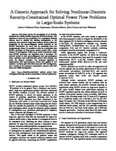
2.1 Formation of a Fisheye Image Fig. 2 depicts the path that is traced by a ray of light in case of a pin-hole camera and a fish-eye lens. In the case of a pin-hole camera, the reflected light ray coming from any object in the real world does not bend towards the normal and continues on the same straight path until the film plane. It is for this reason that the objects in the images that are captured by a pin-hole camera do not suffer any appreciable distortion [8]. However, when the same reflected light ray falls on a fisheye lens, it bends more towards the normal. Because of this, the image captured by fisheye lens suffers from distortion. With increase in the bending of the refracted ray, the distortion in the captured image also increases. This explains why the distortion in fisheye images is more as we move away from the center of the image [8].
A L G O R I T H M
Calculation of image specific parameters
F L O W
Horizontal Stretching/ Horizontal Correction
Alternate Process Non-linear Radial Stretching of Input Image Vertical Stretching/ Vertical Correction
Mapping Matrix Calculation
Rescaling Image to input resolution
Zin
Lens Position Ray refracted due to fisheye lens
Ɵ1
R
r
Ɵ2 Ø
Output Fisheye Corrected Image
Zout
f
Optical Axis
Fig 3: Sample Fisheye Image The description of each step as shown in the flowchart (Fig. 3) is as given below:
2.2.1 Calculate Image specific parameters The area captured by the lens depends on its FoV. FoV of the fisheye lens is given as [9]: (
Q
Ray1
)
From (1),
Ray2 (
)
Fig 2: Fisheye Image Formation As shown in Fig. 2, the ray shown in blue color (Ray1) depicts the path of a reflected ray of light as it passes through a lens of a pinhole camera. The ray shown in red (Ray2), however, shows the path of the same ray when it travels through the fisheye lens. The amount of bending observed, in case of a fish eye lens, depends upon the characteristics of the lens. The proposed algorithm estimates the parameters required for estimating the bend (refraction) in the pixel
M A T R I X F L O W
Picture Plane Ray passing through normal lens
M A P P I N G
The FoV of typical fisheye lenses falls in the range of 120 to 180 degrees. Therefore denominator of (2) varies from 2 to 3. For our experiments, with a FoV of 180 degrees, the focal length is now deduced as:
59
International Journal of Computer Applications (0975 – 8887) Volume 51– No.10, August 2012 It is worth noticing that the ‘f’ calculated is used to normalize the image; thus making the algorithm agnostic of image resolution. The center and height
of the input fisheye image of width is calculated as:
For Ray 1 (5) For Ray 2 (6)
(4) For our proposed approach, all the calculations are done in the polar coordinate system. Therefore, the Cartesian coordinate of each pixel is first converted into its polar coordinate where is the radius and ‘ ’ is the angle calculated with positive X-axis as shown in Fig. 4.
Y-axis
(X’, Y’)
R
(7) Where, is a constant dependent on characteristics of the fisheye lens. Varying would vary the amount of correction in the fisheye image. The constant for a particular fisheye lens can be estimated using heuristic approach. For our experiments, we have fixed the value of to 1.15.
2.2.2 Radial Correction (X, Y)
Now from (5) & (6)
From Fig.2,
r Ɵ Center (Cx, Cy)
X-axis
Fig 4: Image Plane and Assumed Coordinate System Radial lens distortion causes image points on the image plane in the fish-eye camera to be displaced in a nonlinear fashion from their ideal position in the pin-hole camera model. [6]. Fig. 4 depicts the image plane for the set up shown in Fig. 2. When a ray coming from object Q (as seen in Fig. 2), passes through pinhole camera lens it incidents on the image plane at the position denoted by , whereas the same ray incidents at position when passes through fisheye lens. The problem statement is to identify in the pin-hole image corresponding to every position of the input fisheye image. As shown in Fig. 2 let the angle made by ‘Ray1’ and ‘Ray2’ with optical axis be and respectively. Let be the distance of a pixel from center of the output image and be the distance of the same pixel from center but in input fisheye image. Now using Snell’s law,
As shown in Fig. 4, the scene in real world gets mapped in the lesser number of pixels using fisheye lens as compared to the same area captured by pinhole camera. Because of this there will be certain pixel positions in the corrected image where pixel values will be of vacant intensities, which lead to interpolation of the vacant pixel values. In order to avoid interpolation, we proposed an output to input mapping technique viz. for every pixel position in output image, there is a mapping established to the input fisheye from where the pixel value can be estimated. It is evident that this is a one-to-many mapping. The problem statement is now modified to identifying corresponding pixel of the input fisheye image for every pixel in the pin hole image. For inverse mapping, the size of output image is to be estimated based on the size of the input fisheye image. Therefore from (7), (8), and (9) (
(
(
( ))
))
This is output radius for particular input radius . Therefore, to calculate width of the output image, horizontal radius i.e. of input image can be used instead of . Similarly, the height of the output image can be calculated using vertical radius of input image. (
(
(
(
(
(
(
(
⁄
⁄
))
))
(11)
))
))
(12)
60
International Journal of Computer Applications (0975 – 8887) Volume 51– No.10, August 2012 Where and output image.
are half the width and height of the
In order to do reverse mapping, for any pixel we calculate its distance from the center as and find corresponding distance using following equation derived from (7), (8) and (9)
It can be observed from Fig. 6 that after radial correction the convex like appearance of the input image is removed. It can also be noticed that the distortion is not completely eliminated near the image boundaries. The image is, therefore, further stretched in both vertical and horizontal direction in order to correct for these left over distortions.
2.2.3 Vertical Stretching (
(
(
( ))
To make upper and lower boundaries of the radial corrected image straight vertical stretching is performed.
))
Using this , the corresponding coordinate (X’, Y’) in fisheye image can be calculated as:
oh
(14)
ih
(15)
Centre line
The pixel value at of the fish eye image can now be mapped to the pixel location in output image. A typical fish eye image is as shown in Fig 5.
Fig 7: Vertical distance of input and corresponding output pixel As shown in Fig. 7, ‘ih’ shows the input height and ‘oh’ shows the height to which ‘ih’ should be stretched. The stretch factor‘s’ is calculated as:
Fig 5: Input Image The radial corrected output image of Fig.5 is as shown in Fig. 6.
However, every pixel in the column indicated by the red line in Fig. 7 should not be stretched by the same amount. The amount of stretching should increase non-linearly as we move away from the centre. For every vertical distance of the output pixel from the centre of the image corresponding input vertical distance is also calculated using following equation: ( (
(
(
)) ))
Where is the vertical distance of the output pixel and is the correction factor. In order to make stretching non-linear the correction factor should be varied depending upon pixel position. Fig. 8 shows the variation in stretching amount dependent on the correction factor . Fig 6: Radial corrected output of Fig.5
61
International Journal of Computer Applications (0975 – 8887) Volume 51– No.10, August 2012
Horizontal stretching is also carried in the same way as vertical stretching as explained in the above section. The only difference being that instead of the vertical distance; horizontal distance of the pixel from centre is considered. The stretching factor and corresponding input horizontal distance is calculated using (16) and (17).
Output pixel Position Rescaled Pixel Position
1 7 13 19 25 31 37 43 49 55 61 67 73 79 85 91 97 103 109 115
Distance from centre
2.2.4 Horizontal Stretching 180 160 140 120 100 80 60 40 20 0
Sample Points
250
200 150
Output pixel Position Rescaled Pixel Position
100 50 0 1 7 13 19 25 31 37 43 49 55 61 67 73 79 85 91 97 103 109 115
Sample Points (b) Fig 8: Variation in vertical stretching for constant and variable (b)
Fig 10: Intermediate Corrected Output (a)
2.2.5 Image Rescaling While rescaling, we have to reduce the resolution of the image, while keeping the aspect ratio of all object sizes intact. In order to achieve this, we use the formula in (10) with .
Distance from centre
The red curve in Fig. 8 shows the while blue curve shows the . Fig 8(a) is the plot when is kept constant while Fig 8(b) is the plot where is kept varying dependent upon the pixel position. As observed in Fig. 8(a) the pixels near the centre are also getting stretched while in Fig. 8(b) the pixels near the centre are stretched lesser than those closer to the boundaries. And also it can be observed from Fig. 8(b) that non-linearity in stretching has been increased. In order to realize this, in (17) is replaced by the distance of the pixel from the image boundary.
Fig. 10 shows the output after horizontal stretching. The output image obtained at this step is distortion free. However, the image obtained will be much larger in size than that of the input fisheye image because of the radial correction. Therefore, the image obtained here is considered as an intermediate output and needs to be scaled back to the original input size.
120
Output pixel Position
100 80
Rescaled Pixel Position
60 40 20 0 1 7 13 19 25 31 37 43 49 55 61 67 73 79 85 91 97 103 109 115
Distance from centre
(a)
Sample Points Fig 11: Relation between positions of pixels of corrected output and rescaled output Fig 9: Output after Applying Vertical Stretching
62
International Journal of Computer Applications (0975 – 8887) Volume 51– No.10, August 2012 The plot in Fig.11 is obtained by plotting the distances of pixels from centre of the final corrected image as well as that of the rescaled image keeping constant . From Fig. 11 it is clear that rescaling is performed linearly. For vertical rescaling, the vertical shrinking factor can be calculated as follows:
2.2.2). And let coordinate image R.
Let Xr-Map and Yr- Map are two matrices of size (m’ x n’) used to map pixel at position to . Xr-Map stores location while Yr-Map stores location.
(18)
X’
Let be the vertical distance of the pixel in intermediate output and be that of the pixel in final output. is calculated as:
(
(
(
(
))
denotes the pixel position in
Pixel Value
I
Y’
)) (19)
Using (19) height of the intermediate output image can be rescaled to the height of input image. On similar lines, the intermediate output can be shrunk horizontally using (18) and (19). Here we consider the horizontal distance of the pixel from centre of image instead of the vertical distance. After rescaling the intermediate output image, the final output obtained is as shown in Fig. 12.
X Y
Xr-Map
X’
X Yr-Map
Y’
Y
Combined matrix
X Y
R
Fig 13: Calculation of mapping matrix for radial correction Using Xr-map and Yr-Map we can directly obtain radial corrected image without going through actual correction process. Similarly we can calculate the mapping matrices for vertical and horizontal stretching and for rescaling.
Fig 12: Final Output
3. INVERSE MAPPING CALCULATION
MATRIX
The mapping matrix calculation simplifies the complexity of the algorithm and enhances the execution speed. As algorithm works on pixel position one can calibrate the system with two 2D matrices of the size equal to size of image. The advantage of this mapping is all the pixels in output get values from input image leaving no pixel vacant. Let I be input image of size (m x n) and coordinate denotes the pixel position in image I.
Let V and H denote vertically and horizontally stretched images of size (m’ x n’) respectively. Let coordinate (X v, Yv) and (Xh, Yh) denotes the pixel position in vertically and horizontally stretched image respectively. The two matrices Xv-Map, Yv-Map of size (m’ x n’) denote the mapping between vertical stretched image V and radial corrected image R. Let Xh-Map, Yh-Map of size (m’ x n’) denote the mapping between horizontally stretched image H and vertically stretched image V. Let O be rescaled output image of size (m x n) and coordinate (x, y) denotes pixel position in O. Xo-Map and Yo-Map of size (m x n) denotes the mapping between vertically stretched image V to rescaled output image O. Fig. 14 gives relation between all mapping matrices and flow of reverse mapping.
Let R be radial corrected image of size (m’ x n’) (calculation of size of radial corrected image is explained in Section
63
International Journal of Computer Applications (0975 – 8887) Volume 51– No.10, August 2012
X’
I
Y’
X
Xr-Map
Y Radial map
Pixel value
X
X’
v
v
Xv-Map
Y Vertical map
X
X
v
h
Xh-Map
Y Horizontal map
x
Xv-Map
Y
Xh-Map
Y
Xo-Map
Y
Y
h
X
Y’
4. PERFORMANCE CHARACTERISATION
v
X
Yr-Map
Y
Fig. 15 shows a combined matrix of all the corrections. These matrices thus will give the direct mapping between pixel positions in final output (rescaled image) to its corresponding positions in input image. Thus for a particular lens algorithm will calculate the mapping matrix which can be used directly to obtain output image. Due to symmetry of the fisheye image mapping matrix size can further be reduced to one fourth of the image size.
(a)
h
X
v
X
h
Y
Xo-Map
X
h
X
y Rescaling map
h
Y
x
O
y
Fig 14: Calculation Of Mapping Matrices that maps Final Output To Input Fisheye Image From the calculation of all these matrices it is further possible to find a direct relation between a final rescaled output image O and input fisheye I. Therefore every position (x, y) in output image we can map a pixel value from location in fisheye image. Let Xf-Map. Yf-Map be matrices of size (m x n). This matrix directly maps any given pixel in the output corrected image to a corresponding pixel in the input fish-eye distorted image.
X’
(c) Fig 16: Sample frames from a fisheye video showing variation in distortion for a pedestrian crossing It is evident from Fig. 16 that the pedestrian crossing tends to get more distorted as it gets projected away from the image centre. However, in the real world, it is known that the pedestrian crossing is straight and is perpendicular to the road boundary i.e. it has same curvature independent of camera position. Taking this into account, we characterize the performance of the proposed algorithm by calculating the curvature of pedestrian crossing in the distortion free image vis-a-vis the original image. In order to find the variation in curvature, different frames of the pedestrian crossing are considered. The video was captured with the onward looking fisheye camera mounted on a forward moving vehicle. By considering any three points on the pedestrian crossing, it is possible to find the radius of the circle passing through all these points. Once the radius is known, the curvature can be calculated as:
Pixel Value
I
Y’
(b)
v
Where, is some constant of proportionality is the calculated radius of curvature
x y
Xf-Map
X’
x y
Yf-Map
Y’
(a)
x y
(b)
O
Fig 15: Mapping Matrix Giving Direct Relation From Output To Input
(c) Fig 17: Corrected Outputs for Fig. 16
64
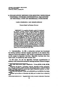
International Journal of Computer Applications (0975 – 8887) Volume 51– No.10, August 2012 After Fig. 17 shows the corresponding output frames for Fig.16. The arrows shown in Fig. 17 denote the corrected pedestrian crossing. After the calculation of curvature for considered input images and for corresponding corrected images, the graph is plotted.
6. ACKNOWLEDGMENTS The authors would sincerely like to thank the all the employees at Centre for Research in Engineering Sciences and Technology (CREST) of KPIT Cummins Infosystems Ltd. for providing an excellent platform, necessary equipment and valuable guidance throughout the course of this research.
7. REFERENCES [1] F. Devernay and O. Faugeras, “Straight lines have to be straight: automatic calibration and removal of distortion from scenes of structured enviroments”. Springer-Verlag Journal of Machine Vision and Applications, 13(1):14– 24, 2001 [2] J.Jedlička, M.Potůčková, Correction Of Radial Distortion In Digital Images, Charles University in Prague, Faculty of Science. Fig 18: Performance Characterisation Curve As shown in Fig.18, the X-axis shows the sequence of frames that were considered and Y-axis gives the curvature values for the input fisheye image as well as the corresponding for corrected images. From the graph, it is evident that as the landmark under consideration comes closer to the fisheye camera; its curvature continues to increase. However, after correction, the curvature of the landmark continues to remain constant across frames; thereby proving the working of our proposed algorithm.
5. CONCLUSION The proposed algorithm was executed on an IBM PC platform with 1GB RAM and Intel® Core™2 processor. The input video was of VGA resolution (640 X 480). The processing speed for calculating the initial mapping matrix was approximately 35msec. With the use of the proposed inverse mapping matrix; the algorithm could run in real-time on any DSP or FPGA platform since all the calculations bubble down to a simple lookup table. The polynomial models used for fisheye correction are not invertible. Hence radial correction using these models leads to vacant pixels in output image. In order to overcome this drawback we have proposed a trigonometric equation for the correction which is invertible. And because of this invertible equation we can find an inverse mapping matrix for a particular lens to avoid all calculations which enhances the execution speed of the algorithm. Also the method proposed is independent of the lens parameters. For any fisheye image corresponding corrected image can be found without knowing the lens specific parameters.
[3] Rickard Strand and Eric Hayman, Correcting Radial Distortion by Circle Fitting, Computational Vision and Active Perception Laboratory (CVAP ) School of Computer Science and Communication Royal Institute of Technology (KTH), SE-100 44 Stockholm, Sweden [4] Michal Kedzierski, Anna Fryskowska, Precise Method Of Fisheye Lens Calibration, Dept. of Remote Sensing and Geoinformation, Military University of Technology, Kaliskiego 2, Str. 00-908 Warsaw, Poland. [5] C. Brauer-Burchardt, K. Voss , A new algorithm to correct fish-eye- and strong wide-angle-lens-distortion from single images, Image Processing, 2001. Proceedings. 2001 International Conference on In Image Processing, 2001., Vol. 1 (2001), pp. 225-228 [6] Ciar´an Hughes, Martin Glavin, Edward Jones and Patrick Denny, Review of Geometric Distortion Compensation in Fish-Eye Cameras, ISSC 2008, Galway, June 18–19 [7] Generating Panoramic Views by Stitching Multiple Fisheye Images, Altera, White Paper [8] A Flexible Architecture for Fisheye Correction in Automotive Rear-View Cameras, Altera, White Paper http://www.altera.com/literature/wp/wp-01073-flexiblearchitecture-fisheye-correction-automotive-rear-viewcameras.pdf [9] Fisheye lens: http://en.wikipedia.org/wiki/Fisheye_lens
65