Oct 1, 2014 - processing domain. Hardware designers are ... cheap and fast programmable silicon among the most advanced fabrication processes [11]. ..... horizontal shift register shifts each pixel horizontally so that after hor slide shifts for ...
A Generic Pixel Distribution Architecture for Parallel Video Processing Karim M. A. Ali, Rabie Ben Atitallah, Sa¨ıd Hanafi, Jean-Luc Dekeyser
To cite this version: Karim M. A. Ali, Rabie Ben Atitallah, Sa¨ıd Hanafi, Jean-Luc Dekeyser. A Generic Pixel Distribution Architecture for Parallel Video Processing. International Conference on Reconfigurable Computing and FPGAs - ReConFig 2014, Dec 2014, Cancun, Mexico. 2014.
HAL Id: hal-01070541 https://hal.inria.fr/hal-01070541 Submitted on 1 Oct 2014
HAL is a multi-disciplinary open access archive for the deposit and dissemination of scientific research documents, whether they are published or not. The documents may come from teaching and research institutions in France or abroad, or from public or private research centers.
L’archive ouverte pluridisciplinaire HAL, est destin´ee au d´epˆot et `a la diffusion de documents scientifiques de niveau recherche, publi´es ou non, ´emanant des ´etablissements d’enseignement et de recherche fran¸cais ou ´etrangers, des laboratoires publics ou priv´es.
A Generic Pixel Distribution Architecture for Parallel Video Processing
Abstract—I/O data distribution for neighbourhood operations processed in parallel computing dominates the multimedia video processing domain. Hardware designers are confronted with the challenge of architecture obsolescence due to the lack of flexibility to adapt the I/O system while upgrading the parallelism level. The usage of reconfigurable computing solves the problem partially with the capability of hardware partitioning according to the application requirements.
high computation rates and low power consumption) and the production cost. Certainly, this design methodology leads to an efficient system. However, ever-changing in the application requirements (for better resolution, less power consumption, etc.) demands the re-design of the I/O data distribution architecture as well as the underlying processing hardware, leading to the system obsolescence.
Taking this aspect into consideration, we propose a generic I/O data distribution model dedicated to parallel video processing. Several parameters can be configured according to the required size of macro-block with the possibility to control the sliding step in both horizontal and vertical directions. The generated model is used as a part of the parallel architecture processing multimedia applications. We implemented our architecture on the Xilinx Zynq ZC706 FPGA evaluation board for two applications: the video downscaler (1:16) and the convolution filter.
In this paper, we will focus on the challenge of developing a generic model for pixel distribution dedicated to streaming video applications. Indeed, there is a strong demand for such efficient and flexible model to distribute the data onto parallel hardware architectures to meet the real-time constraints. In the case of HD frames with high processing rates, huge amount of memory is required to store the input image stream. This consumes a lot of power and restricts the parallel processing level due to the limited memory bandwidth. According to the global constraints, the efficient distribution of pixels leads to well-balance between the I/O system performance and the processing rate. High-level parameters should be defined to help multimedia hardware designers to configure their architecture and to implement easily this filed of applications in FPGAs. In order to improve the productivity, FPGAs will be used in the frame of an IP-based design methodology, advocating the All IP paradigm, in order to favor the reuse when the requirements change.
The efficiency of our system for distributing pixels among parallel IPs is demonstrated through several experiments. The experimental results show the increase in the design productivity using the automatic code generation, the low hardware cost of our solution and how flexible is the model to be configured for different distribution scenarios.
I.
I NTRODUCTION
Nowadays, embedded video processing applications are becoming more and more widespread in multimedia systems. Two main aspects characterize these applications. The first aspect involves the data structures, which are processed in general in the form of different macro-block sizes according to the neighbourhood processing algorithm. Video scaling, median filter, and convolution transformation are examples of macro-block-based video processing. In addition, these data come from High Definition (HD) streaming image sensors supporting high frame rates. The second aspect concerns the potential parallelism available in the application functionality. These two aspects lead to high requirements in terms of processing power and buffering capacity. Hence, the hardware designers are obliged to come up with new architecture for executing this field of applications. An unavoidable solution to meet the performance and flexibility goals consists in using FPGAs that offer high computation rates per watt and adaptability to the application constraints. Today, FPGAs are increasingly used to build complex integrated video processing applications. FPGAs offer cheap and fast programmable silicon among the most advanced fabrication processes [11]. Furthermore, FPGA technology enables to implement massively parallel architectures due to the huge number of programmable logic fabrics available on the chip [4]. However, most of the designed solutions in the literature aim for customizing the architectures to balance the implementation constraints between the application needs (i.e.
To address the above challenge, we propose a generic hardware model to implement a flexible pixel distributor that can be configured without modifying its internal structure. The VHDL files of the pixel distributor can be easily generated for different sizes of macro-block using a script file. The distribution of pixels is set up by fixing the model parameters of the architecture in order to produce macro-blocks respecting the image processing algorithm and the parallelism level. After setting the parameters, our pixel distributor can be considered as an IP and used as an essential part of a parallel architecture, thus it reduces significantly the design complexity and increases the development productivity. The rest of the paper is organized as follows. Section II describes the state-of-the-art. Section III describes the video processing system architecture. Section IV details the architecture of our generic pixel distribution model. Next, in Section V we show the results obtained using our architecture. Finally we conclude with conclusion and future works in Section VI. II.
R ELATED W ORKS
Several benefits emphasize hardware designers to redirect their efforts to reconfigurable computing for implementing video-based multimedia applications. Indeed, FPGA technology could offer better performances comparing to CPUs or
VTC_ 1
VTC_ 0
VITA image sensor receiver
DPC
CFA
Image Processing IPs
Gamma
RGB to YCbCr422
Image preprocessing pipeline
Fig. 1: Video processing system architecture
GPUs up to 10x [1] [5] [12] at lower frequencies. Furthermore, designers could exploit the parallelism intrinsic in the application to adapt the architecture according to the timing constraints and thus to optimize the hardware resources [2]. In such architecture, data I/O operations such as buffering or distribution for parallel computing become critical aspects while streaming frames with high rates. Several research works have been devoted to design I/O systems dedicated to data dominated applications in order to reduce the local memory storage, the interconnection cost, or power consumption [9]. In the scope of this paper, we will focus on the hardware realization of neighbourhood operations. Due to the large spectrum of image processing algorithms, the favourite solution for designers is to customize the hardware implementation on FPGAs. As an example, authors present in [8] an efficient cyclic image storage structure for direct calculation of 2D neighbourhood operations by using dual port Block RAM (BRAM) buffers. Their architecture optimizes the area utilization comparing to the common solution that uses long shift register pipelines. This technique is widely used due to the large BRAMs available in the current FPGA generations. However the main drawback of such solution is the lack of design flexibility to be adapted according to the neighbourhood operations. Today, multimedia application designers on FPGAs need a generic model that can be configured according to the application requirements with low complexity and hardware cost. To address the above challenge, authors in [7] present a compile-time approach to reuse data in window-based codes using the ROCCC (Riverside Optimizing Configurable Computing Compiler) tool. The main objective is to exploit the data reuse on the FPGA to minimize the required memory or I/O bandwidth while maximizing parallelism. However, the generated HDL code with the compiler can’t achieve the performances of a manually HDL code written by a hardware engineer [7]. III.
V IDEO PROCESSING SYSTEM ARCHITECTURE
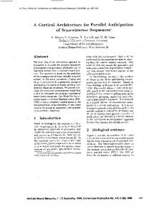
The whole video processing chain depicted in Fig. 1 is implemented on Xilinx Zynq ZC706 FPGA evaluation board [13]. The VITA-2000 image sensor [10] configured for 1080p60 resolution is connected to the FPGA board through the Avnet IMAGEON FMC module [3]. The image sensor captures one of the three color components of a pixel in raw format (10-bit) then through the image preprocessing pipeline the raw pixel is converted to the RGB format (24-bit).
clk vblank hblank active_video data
Fig. 2: Video timing signals
The blocks of the image preprocessing pipeline are connected to a processor through an AXI bus for initial configurations (not mentioned in the figure for simplicity). The first stage in the image preprocessing pipeline is the Defective Pixel Correction (DPC) filter where the defective pixels are removed. The captured pixel is then corrected by the Color Filter Array (CFA) filter to restore the other two colors based on the neighbouring pixels. Some other filters (gamma, noise, edge enhancement, ....) can be added to improve the quality of the input image. The Video Timing Controller (VTC) is used at the input and the output side of the chain for detecting and generating the required synchronization video signals. The block named Image Processing IPs represents a set of parallel IPs used to implement a certain image processing algorithm. Through the RGB-to-YCbCr422 block, the pixel in the RGB format is converted to the YCbCr 4:2:2 format then streamed with correct video signals to the HD monitor according to the HDMI specifications . In this work, we present how the input stream of pixels can be distributed for parallel processing then collected to be displayed on an HD monitor through the HDMI port mounted on Zynq ZC706 evaluation board. Figure 2 shows the video signals accompanied with the input stream. The start of the frame is observed when the vblank signal is high and the start of a line is noted when the hblank signal is high while a valid pixel is presented when the active video signal is asserted to high. IV.
G ENERIC PIXEL DISTRIBUTION MODEL
The main objective of this section is to introduce our generic pixel distributor model. As stated before, our main concern is to propose a pixel distribution architecture that can deal with various input frames and macro-blocks sizes. First, we will introduce the different model parameters of the generic pixel distribution system. Second, the proposed hardware architecture will be detailed and finally, we will describe the finite state machines that control the architecture.
horizontal shift register
clk
pixel< 1 >
clk rst
pixel< 2 > clk
. . .
rst
rst
line buffers
pixel< H >
rst
video_data
rd_clk wr_clk
line buffer 1
|
line buffer 2
wr_en_buff(i)
line buffer 3
. . . .
wr_addr rd_addr
circular vertical shifter
pixel< 1 ,..., H >
pixel< H+1 ,...,2*H>
pixel< 2*H+1 ,….,3*H >
D
D
D ... D
D
D
D
... D
D
D ... D
D
pixel< H+1 > pixel< H+2 >
. . . . pixel< (V-1)*H+1 ,…., V*H >
line buffer V
D
D ... D
. . .
pixel< 2*H > pixel< 2*H+1 > pixel< 2*H+2 >
D
. . .
pixel< 3*H > pixel< (V-1)*H+1 > pixel< (V-1)*H+2 >
. . .
ver_shifting
|
|
|
V
pixel< V*H >
vblank hblank
sof
controller
act_video
sof
D
valid
valid
D
Pixel Distributor
Fig. 3: Pixel distributor structure
frame_wid procd_ num_cols
frame_len procd_num_lines V
H
•
A macro-block is the basic processing structure of length V and width H such that V ≥ 1 and H ≥ 1
•
A macro-block can move horizontally by a step = hor slide and vertically by a step = ver slide such that 1≤ ver slide ≤V and 1≤ hor slide ≤ H
•
procd num lines is the number of lines processed in one frame. If the procd num lines < frame len then (frame len - procd num lines) lines aren’t processed, such that len−V procd num lines = V + b frame (1) ver slide c ∗ ver slide
•
procd num cols is the number of pixels processed in one line. If the procd num cols < frame wid then (frame wid - procd num cols) pixels aren’t processed, such that wid−H procd num cols = H + b frame (2) hor slide c ∗ hor slide
•
N is the index of a line in the frame such that 1 ≤ N ≤ procd num lines
•
Since each line is stored in a separate buffer, then V buffers are needed. we define B as the buffer index of a given line such that B = (N mod V) (3)
hor_slide
ver_slide
N
Fig. 4: Pixel distribution model
A. Model Parameters The required parameters to understand the pixel distribution model are described below and illustrated in Fig. 4: •
A frame is of width frame wid and length frame len
vblank = 1
waiting for a frame Idle
vblank = 1
Start of frame
waiting until the last pixel of the first column is written
waiting for a frame
vblank = 0
Start of line
hblank = 1 start of frame
Idle
first column
vblank = 1 active_video = 1
vblank = 1 active_video =0
Non-padded Pixels
active_video =0
bypassing non-padded pixels
Writing pixels
waiting until the last pixel of the next first column is written
active_video =1
Fig. 5: The finite state machine for the writing process
B. System Architecture The role of the pixel distributor is to write the input video stream to the line buffers and then to distribute the pixels in the form of macro-blocks according to the required size (H x V). Figure 3 shows the interface and the internal block diagram for the pixel distributor. The interface consists of (i) the input ports for the video signals (vblank, hblank, act video) and the video data, (ii) the output ports are equal to the number of the pixels of the macro-block (H x V); in addition to that, the signal sof comes with the first macro-block to designate the start of the frame while the valid signal comes with every macro-block to indicate the presence of a valid block at the output ports. The pixel distributor consists of the following internal blocks: (i) the line buffers for storing the input pixels, (ii) the circular vertical shifter for shifting the pixels circularly in the vertical direction, while (iii) the horizontal shift register for shifting the pixels horizontally, (iv) the controller for asserting the required control signals according to the current state of the system; for example, the controller asserts wr en buff signal to enable writing in one of the line buffers at a specified address wr addr, while it loads rd addr for read operations; the controller assigns sof, valid and ver shifting signals for indicating the start of the frame, the presence of a valid macroblock or for shifting the pixels vertically. A column of pixels is passed to the circular vertical shifter as soon as, its last pixel was written to the line buffers. The horizontal shift register shifts each pixel horizontally so that after hor slide shifts for the first pixel of the macro-block (i.e. pixel), the valid signal is asserted to indicate the presence of a macro-block at the output ports of the pixel distributor. From equation 3, the line of index V+1 will be stored in the first line buffer. If ver slide < V, then the line V+1 will have some order in the macro-block rather than being the first line. In this case, the output of the line buffers are needed to be shifted vertically in a circular way to put back the lines of the macro-block in their correct order. Every V lines, the signal ver shifting is asserted ver slide times.
next first column
end of the frame
reading the first column from line buffers waiting for the next first column
reading the first column from line buffers
Reading macro-blocks
distributing macro-blocks
Fig. 6: The finite state machine for the reading process
C. The Controller Finite State Machine Figure 5 shows the finite state machine for the writing process, (i) the system starts at the idle state waiting for an input stream, (ii) during the vblank period, the system waits in the start of frame state; then, (iii) it waits in the start of line state while the signal hblank is active, (iv) the system rests at the writing pixels state during the writing operation of the pixels, (v) according to equation (2), if procd num cols < frame wid then the system will transit to non-padded pixels state to bypass the rest of the pixels of the line, otherwise; it will transit to the start of line state to process the next line or to the start of frame state to process the next input frame. Figure 6 shows the states for the reading process, (i) the system starts at the idle state waiting for an input stream; then, (ii) it waits in the state first column until the first column of the macro-block is written to the line buffers, (iii) in the reading macro-blocks state, the macro-blocks are sent to the circular vertical shifter , as soon as they are written to the line buffers, (iv) after that, the system will transit to the next first column state waiting for the first column of the next set of macroblocks or it will transit to the idle state waiting for the new input frame. D. Generic Model The process of writing/reading pixels to/from the line buffers doesn’t depend either on the size of the macro-block or on the size of the input frame. Only the number of line buffers depend on the vertical size of the macro-block (V) and the number of the output ports depend on the size of the macro-block (H x V). Therefore, the VHDL files of the pixel distributor can be easily generated for different sizes of macro-block by modifying only the number of buffers in the line buffers and the number of the output ports using a script file. E. Parallel Processing The communication between the pixel distributor and the processing IPs is done through the valid signal. The pixel distributor asserts the valid signal when a macro-block is available at its output ports (i.e. the input ports of the IP). Figure 7
A. Automatic Code Generation IP Pixel Distributor
. Demux ...
sof valid
| data
.. .. .. .
.. valid .. .. Mux .. | data ..
IP
Fig. 7: Parallel structure
depicts the architecture for parallel processing, where a demux is used to distribute the valid signal each time between different parallel IPs. From the pixel distributor model, the rate of producing macro-blocks is equal to macro-block rate = hor 1slide in macro-block/cycle. If the computation delay of an IP is equal to computation delay in clock cycles then the required number of parallel IPs can be calculated from the following equation: Number of parallel IPs =dmacro-block rate ∗ computation delaye =d
computation delay e hor slide
(4) F. Pixel Collector The size of the output frame can be equal to the input frame as in the case of grayscale filter or less than it as in the case of the video downscaler. Since the result is streamed on HD1080 monitor; therefore, the pixel collector have to produce frames respecting the same frame size (1920x1080). When the output frame is smaller than the HD1080 frame size, the border parameters of the pixel collector (left border, right border, up border, bottom border) are configured to pad the frame to HD1080 format. G. Limitation The distribution of pixels is executed within the boundaries of the frame; therefore, for the neighborhood pixel applications like median filter, the border pixels are not distributed since a part of their macro-blocks lie outside the frame boundaries. In such situation, we decided not to process these border pixels since the percentage of the unprocessed pixels (i.e. the error rate) is within the acceptable range. for example, when the input frame size is 1920x1080, the percentage of the unprocessed pixels is 0.29% for a macro-block of size=3x3, 0.58% for 5x5 and is 0.86% for 7x7. V.
E XPERIMENTAL R ESULTS
Firstly, we will highlight the advantages of the automatic code generation phase. Secondly, we will present the synthesis results for the pixel distributor for different macro-block sizes as well as for different frame sizes. Finally, we will illustrate examples making profit from the proposed parallel structure described in the previous section. Two application examples are implemented: video downscaler (1:16) and convolution filter.
We have developed a tool that takes the length H and the width V of the macro-block as inputs to generate the required VHDL code files for the pixel distributor. Using a host machine equipped with Intel(R) Core i7 processor and a 16 GB RAM more than 700 lines were generated automatically for a pixel distributor of macro-block size=4x4. This is a significant result compared to the manual coding of the same distribution design which can take hours of development; thus, the design productivity increases. By using our model, when the macro-block size or the sliding window step is changed; the designer does not need to redesign of the pixel distributor but few parameters can be modified in the tool and after few seconds the required files are generated. The code generation tool generates a set of files containing the description for the circular vertical shifter, the horizontal shift register, the line buffer as well as the top level module for the pixel distributor. The tool helps the designer to obtain the required files particularly when the number of code lines increases with larger macro-block sizes. For instance, the code size grows from more than 700 lines for macro-block=4x4 to more than 2000 lines for macro-block=16x16 as shown in Table I. Generated files
Description
pixel distributor.vhd cir ver shifter.vhd hor shift reg.vhd buff.vhd
The top level of the pixel distributor The circular vertical shifter component The horizontal shift register component It constructs the line buffers component
Number of code lines 4x4 8x8 16x16 500 670 1300 80 95 127 83 190 600 60 60 60
TABLE I: Generated VHDL code files for the pixel distributor
B. Pixel Distributor Synthesis Results Table II shows the synthesis results for the pixel distributor over the Zynq XC7Z045-FFG900 evaluation board. The pixel distributor was synthesized for the following model parameters (macro-block size=4x4, hor slide=1 and ver slide=1) with different frame sizes (HD1080, HD720, SVGA and VGA). The results show that the size of the controller in terms of slice register and slice LUT differs according to the frame size. This occurs because the size of the internal counters used by the controller during the read/write process depends on the size of the input frame. While for the other components, they are almost occupying the same area because their size depends only on the macro-block size which was fixed to 4x4 during this experiment. Table III shows the synthesis results for the pixel distributor for fixed frame size (HD1080) with hor slide=1, ver slide=1 and different sizes of macro-block (1x3, 2x2, 3x1, 4x4,....). From the results, we can notice that the circular vertical shifter has almost the same area while the V parameter is fixed for macro-block of sizes 4x4, 5x4 and 6x4 as shown in Table III. For the horizontal shift register, it has the same area for distributors of the same number of output pixels as shown in the case of 3x1 and 1x3 or in the case of 4x6, 6x4 and 3x8. Based on the synthesis results, the maximum operating frequency for the pixel distributor is higher than the required one for HD1080 processed at 60 frame/sec (i.e. 148.5 MHz).
SOF valid
..
SOF vblank hblank act_video data[23:16]
Demux
valid
Pixel Distributor_R
SOF valid
data . 0
..
..
data 15
SOF valid
..
SOF vblank hblank act_video data[15:8]
Demux
valid
Pixel Distributor_G
SOF valid
data . 0
..
..
data 15
SOF valid
..
SOF vblank hblank act_video data[7:0]
Demux
valid
Pixel Distributor_B
SOF valid
data . 0
..
..
data 15
Video Scaling 4x4 Video Scaling 4x4 Video Scaling 4x4 Video Scaling 4x4 Video Scaling 4x4 Video Scaling 4x4
SOF valid data SOF valid data
Mux
SOF valid data
Mux
SOF valid data
Mux
SOF valid data
SOF valid data SOF valid data
SOF valid data SOF valid data
vblank hblank
Pixel act_video Collector data[23:0]
Fig. 8: Parallel architecture for the video downscaler
0
0
0
130
0 4 4
87 0 219
174 0 208 267.95
0
0
0
130
0 4 4
84 0 216
159 0 195 266.17
BRAM18
92 0 224
36
Slice LUT
130
0 4 4
2
Slice Reg
0
BRAM18
34
Slice LUT
0 173 0 209 268.53
2
640x480
Slice Reg
0
95 0 227
BRAM18
36
130
Slice LUT
BRAM18
2
800x600
Slice Reg
Slice LUT
Circular vertical shifter Horizontal shift register Controller Line buffers Total Freq(MHz)
1280x720
Slice Reg
1920x1080
2
34
0
0
0
163 0 197 269.40
0 4 4
TABLE II: Synthesis results for pixel distributor for model parameters (macro-block=4x4 with hor slide=1 and ver slide=1) with different frame sizes
Line buffers
Freq (MHz)
Slice Reg
Slice LUT
BRAM18
Slice Reg
Slice LUT
BRAM18
Total
Slice LUT
3 2 1 8 4 6 4 7 4
Controller
Slice Reg
x x x x x x x x x
Horizontal shift register
Slice LUT
1 2 3 3 4 4 5 5 6
Circular vertical shifter Slice Reg
Macro-block size ( H x V)
2 1 0 3 2 3 2 3 2
29 9 0 134 36 107 35 144 36
26 34 26 194 130 194 162 282 194
0 0 0 0 0 0 0 0 0
83 94 92 88 95 95 95 94 95
145 170 176 170 173 178 183 183 175
3 2 1 8 4 6 4 7 4
111 129 118 285 227 292 259 379 291
174 179 176 304 209 285 218 327 211
3 2 1 8 4 6 4 7 4
289.27 269.98 269.98 259.87 268.53 267.59 257.69 244.92 268.53
TABLE III: Synthesis results for pixel distributor for HD1080 frame, hor slide=1, ver slide=1 and different macro-block sizes
C. Video Downscaler (1:16) The video downscaler scales the HD1080 frame (1920x1080) to one sixteenth of its size (480x270). The
application was realized over the Zynq XC7Z045-FFG900 platform according to the video processing system architecture shown in Fig. 1. Figure 8 shows in details the structure of the Image Processing IPs block. The video downscaler has a separate processing channel for each color component (red, green and blue). The data distributor was configured with the following model parameters (macro-block size=4x4, hor slide=4 and ver slide=4). The computation delay for the VideoScaling 4x4 IP is 8 clock cycles. By applying equation 4, we can deduce that the required number of parallel IPs is 2; thus, we had two VideoScaling 4x4 IPs working simultaneously for each processing channel. The Demux component is used to branch the control signals (valid and sof ) over the IPs for parallel processing. While the Mux component is used to gather the processed data and control signals from the parallel IPs to send them to the pixel collector. In the pixel collector, the coming pixels are stored in order and when there are enough pixels in the buffer, it starts streaming the video frame with corresponding video signals (vblank, hblank and active video) to the HDMI output port. The output frame can be placed in the middle of the screen by setting the border parameters of the pixel collector to (left border=720, right border=720, up border=405, bottom border=405). Table IV shows the synthesis results for the video downscaler. The video downscaler occupies 4.8% and 9.3% of the total available resources for slice register and slice LUT respectively. The parallel processing channels consume nearly 9.7% of the total slice register used and 8.6% of that used for slice LUT. The pixel distributor utilizes around 3.2% of the total design area for both slice register and slice LUT; thus, it represents a low hardware design cost. For the BRAM utilization, the video downscaler shows around 22% of the total available BRAM on the board since the collector keeps the pixels for one scaled frame (480x270) before starting the
SOF valid
.. SOF valid
.. SOF valid
valid
Demux SOF
.. SOF valid
.. SOF valid
..
Pixel Distributor_R
SOF valid
data . 0
..
..
data 8
Conv 3x3
Conv 3x3
Conv 3x3
Conv 3x3
Conv 3x3
SOF valid data SOF valid data
SOF valid data SOF valid data
Mux
SOF valid data
Pixel Collector
vblank hblank act_video data[23:0]
SOF valid data SOF valid data
~~
vblank hblank act_video data[23:16]
Conv 3x3
DSP48E1
Video processing system architecture Video timing controller 0 1209 1230 0 VITA image sensor 5941 6331 0 receiver Image preprocessing 10565 9733 19 pipeline RGB-to-YCbCr422 254 202 0 Video timing controller 1 1093 1114 0 Total 19062 18610 19 Video downscaler Pixel distributor (R,G,B) 669 639 12 Demux (R,G,B) 3 9 0 Video scaling (R,G,B) 1140 756 0 Mux (R,G,B) 90 42 0 Pixel collector (R,G,B) 154 307 0 Total 2056 1753 12 Total application area 21118 20363 31 Resource utilization (%) 4.83 9.32 2.8 Convolution filter Pixel distributor (R,G,B) 507 630 9 Demux (R,G,B) 9 27 0 Conv. filter (R,G,B) 4410 2844 0 Mux (R,G,B) 210 99 0 Pixel collector (R,G,B) 132 325 0 Total 5268 3925 9 Total application area 24330 22535 28 Resource utilization (%) 5.56 10.31 2.57
BRAM36
BRAM18
Slice LUT
Slice Reg
Fig. 9: The red color processing channel for convolution filter
0
0
13
4
10
9
0 0 23
4 0 17
0 0 0 0 96 96 119 22
0 0 0 0 0 0 17 1.89
0 0 0 0 72 72 95 17.61
0 0 0 0 0 0 17
TABLE IV: Synthesis results for the video downscaler (1:16) and convolution filter
it will be for the green and blue colors. The input stream is distributed by the pixel distributor in the form of macroblocks of size=3x3 with hor slide=1 and ver slide=1. The computation delay for the Conv 3x3 IP is 6 clock cycles so by using equation 4, the required number of Conv 3x3 IPs for each channel is 6 IPs running at the same time to process the distributed macro-blocks. The Demux and Mux components are used for branching and gathering the data and the control signals through the parallel architecture. Due to the limitation described in subsection IV-G, the border pixels are not processed so the pixel collector produces the output frame with a contour of black pixels. The border parameters of the pixel collector were set to the following values (left border=1, right border=1, up border=1, bottom border=1). As shown in Table IV, the convolution filter has 5.5% of the total available slice register and 10.3% of that available for slice LUT. The parallel processing channels occupies 21.7% and 17.4% of the total design utilization for slice register and slice LUT. This percentage rises due to the presence of 6 parallel Conv 3x3 IP working at the same time for each processing color channel. The pixel distributor shows less than 3% for both resources which proves the low hardware cost of our solution. For the BRAM utilization, the collector starts streaming at the time it receives the first processed macroblock; however, the frame starts with a vblank period and consequently the pixels have to be stored during that period. For this reason, the convolution filter takes around 17.6% of the total available BRAM resources.
output stream. VI. D. Convolution Filter Based on the same video processing architecture shown in Fig. 1, a convolution filter [6] with kernel [-1, -1, -1, -1, 9, -1, 1, -1, -1] is applied to the HD1080 input frame captured by the VITA image sensor. In this application, a processing channel is dedicated for each color component. Figure 9 shows the processing channel for the red color component and similarly
C ONCLUSION
For multimedia video processing domain, reconfigurable fabric (FPGA) is a promising technology that offers high integration density, real-time processing and low power design. Furthermore, it provides an efficient execution support by exploiting the spatial and temporal parallelism inherent from the application functionality. In this paper, we leverage the I/O system design to provide a generic model for pixel distribution
dedicated for streaming video applications with low hardware cost (around 3% of the total design area for both video downscaler and the convolution filter). The pixel distributor has a flexible model; we can obtain the required VHDL files by setting the size of the macro-block in the code generation tool without spending more redesign efforts. As a future work, first we will focus on the design of massively parallel reconfigurable architectures that make profit from our generic I/O system to support SPMD (Single Program Multiple Data) execution model. Second, we plan to reconfigure the I/O system at runtime according to the active processing elements relying on the partial reconfiguration feature offered by recent FPGA generation. R EFERENCES [1]
[2]
[3] [4]
[5]
[6] [7]
[8]
[9]
[10] [11]
[12]
[13]
S. Asano, T. Maruyama, and Y. Yamaguchi. Performance Comparison of FPGA, GPU AND CPU in Image Processing. In 19th IEEE International Conference on Field Programmable Logic and Applications, FPL, Prague, Czech Republic, Aug. 2009. W. Atabany and P. Degenaar. Parallelism to reduce power consumption on fpga spatiotemporal image processing. In IEEE International Symposium on Circuits and Systems (ISCAS), pages 1476–1479. IEEE, 2008. Avent. FMC-IMAGEON EDK Reference Design Tutorial. M. Baklouti, Y. Aydi, P. Marquet, J.-L. Dekeyser, and M. Abid. Scalable mpNoC for massively parallel systems - Design and implementation on FPGA. Journal of Systems Architecture, 56(7):278 – 292, 2010. Special Issue on HW/SW Co-Design: Systems and Networks on Chip. J. Fowers, G. Brown, P. Cooke, and G. Stitt. A performance and energy comparison of fpgas, gpus, and multicores for sliding-window applications. In Proceedings of the ACM/SIGDA International Symposium on Field Programmable Gate Arrays, FPGA ’12, pages 47–56, New York, NY, USA, 2012. ACM. R. Gonzalez and R. Woods. Digital Image Processing. Pearson Education, 2011. Z. Guo, B. Buyukkurt, and W. Najjar. Input data reuse in compiling window operations onto reconfigurable hardware. In Proceedings of the 2004 ACM SIGPLAN/SIGBED Conference on Languages, Compilers, and Tools for Embedded Systems, LCTES ’04, pages 249–256, New York, NY, USA, 2004. ACM. M. Holzer, F. Schumacher, I. Flores, T. Greiner, and W. Rosenstiel. A real time video processing framework for hardware realization of neighborhood operations with fpgas. In Radioelektronika (RADIOELEKTRONIKA), 2011 21st International Conference, pages 1–4, April 2011. N. Lawal and M. ONils. Embedded FPGA memory requirements for real-time video processing applications. In 23rd NORCHIP Conference, Oulu, Finland, Nov. 2005. ON semiconductor. VITA 2000 2.3 Megapixel 92 FPS Global Shutter CMOS Image Sensor. S. Qasim, S. Abbasi, and B. Almashary. An overview of advanced fpga architectures for optimized hardware realization of computation intensive algorithms. In Multimedia, Signal Processing and Communication Technologies, 2009. IMPACT ’09. International, pages 300–303, March 2009. T. Saegusa, T. Maruyama, and Y. Yamaguchi. How fast is an fpga in image processing? In Field Programmable Logic and Applications, 2008. FPL 2008. International Conference on, pages 77–82, Sept 2008. Xilinx. ZC706 Evaluation Board for the Zynq-7000 XC7Z045 All Programmable SoC User Guide.