A Graph-based Approach to Transform XML Documents Gabriele Taentzer1 and Giovanni Toffetti Carughi2 1
Technische Universit¨ at Berlin, Germany
[email protected] 2 Politecnico di Milano, Italy
[email protected]
Abstract. As XML diffusion keeps increasing, it is today common practice for most developers to deal with XML parsing and transformation. XML is used as format to e.g. render data, query documents, deal with Web services, generate code from a model or perform model transformation. Nowadays XSLT is the most common language for XML transformation. But, although meant to be simple, coding in XSLT can become quite a challenge, if the coding approach does not only depend on the structure of the source document, but the order of template application is also dictated by target document structure. This is the case especially when dealing with transformations between visual models. We propose to use a graph-based approach to simplify the transformation definition process where graphs representing documents are transformed in a rulebased manner, as in XSLT. The differences to XSLT are mainly that rules can be developed visually, are more abstract (since the order of execution does not depend on the target document), IDREFs are dealt with much more naturally, and due to typed transformations, the output document is guaranteed to be valid with respect to the target schema. Moreover, graph-based transformation definitions can be automatically reversed in most cases. This is especially useful in model transformation (e.g. in OMG’s MDA approach).
1
Introduction
When XML (Extensible Markup Language) [14] was being developed, the proposing working group at W3C had clear design goals in mind: they wanted to come up with a language which was at the same time formal, concise, easy to process for applications and to read and write for human beings. Today XML is used in virtually any IT domain as the most natural form to represent structured or (especially) semi-structured data. This includes usage of XML to store information, serialize models, communicate over the Internet, etc. As a consequence of this diffusion, it is common practice for most of today’s programmers to deal with XML parsing and transformation, be it to render data, query documents, deal with web services, generate code from a model or perform model transformation.
XSLT (the Extensible Stylesheet Language Transformations [16]) is the language proposed by the W3C to deal with XML document transformation. Although developed to enable most IT developers to easily specify transformations, there are cases in which writing XSLT can be quite hard. The reasons are that, especially when dealing with model to model transformation, the coding approach does not only depend on the structure of the source document, but the order of template application is also dictated by target document structure. In addition to this, extensive use of IDREFs (i.e. references to other elements) can force developers to complicated composition of recursion, variables or keys to hop around the XML tree representation looking for some element. We propose to use a graph-based approach to simplify the transformation definition process. Whether or not XML documents conform to a given document type definition (DTD) or XML Schema, typing information can be inferred and represented by so-called type graphs. Any XML document can therefore be represented as a typed graph and transformed in a rule-based manner, as in XSLT. The differences toward XSLT are mainly that rules can be depicted visually, are more abstract (so the order of execution does not depend on target document), IDREFs are dealt with much more naturally, and because of typing, the transformation output is guaranteed valid with respect to the target schema. Often transformations between XML formats are needed back and forth, e.g. a UML model is translated to some semantic domain (for example Petri nets) to do some validation and the result which might be a change proposal, has to be translated back. We show that graph rules can be automatically reversed in certain cases, to formulate a reverse XML transformation. The new approach for XML transformations has been tested at a variety of different transformations. Throughout this paper we discuss the transformation of class diagrams in XMI [18] format to entity-relationship diagrams in WebML [13] format, and back. The paper is organized as follows: Section 2 introduces to the main concepts of XML and XSLT and illustrates them at the running example, an XML transformation from XMI to WebML. Section 3 gives an introduction into the basic graph transformation concepts which is used in section 4 to define our graph-based approach to XML transformation. This approach is applied to the running example in section 5. Thereafter, we discuss the possibilities to reverse XML transformations automatically in section 6. Related approaches and a short conclusion can be found in section 7.
2
XML and XSLT
XML Documents The Extensible Markup Language (XML) [14] is a simple, very flexible text format derived from SGML (ISO 8879 [11]). Originally designed to meet the challenges of large-scale electronic publishing, XML is playing an increasingly important role in the exchange of a wide variety of data on the Web and elsewhere. XML documents are composed of markup and content, a snippet of an XML document is shown below. This example is an extract of a WebML
(Web Modeling Language [13]) document representing an Entity-Relationship diagram. ...
The basic kinds of markup which can occur in the XML document content are the following: – Elements are indicated by opening and closing tags (with angle brackets) and may contain other nested elements. If they don’t they may also be written as a single in-line tag (e.g. ). – Attributes are pairs composed of a name and a quoted-value inside start-tags after the element name. Additionally, entities, comments, and CDATA sections are allowed as building blocks of XML (besides processing instructions). XSL Transformations Two W3C Recommendations, XSLT and XPath (the XML Path Language [15]), are provided to allow for transformation of a source XML document into another document written in any language. We use XSLT, which itself uses XPath, to specify how an implementation of an XSLT processor is to create our desired output from our given marked-up input. XML documents are represented as trees: XSLT provides constructs to navigate through nodes, iterate, and eventually produce new nodes in the output document, XPATH provides a way to select or express conditions regarding a node given a starting context of application. XSLT is a declarative language, the XSLT processor is not told how to perform the transformation, rather XSLT describes the expected result with respect to the source document structure. This allows a stylesheet to
be applicable to a wide class of documents that have similar source tree structures. There are two approaches to stylesheet design: ’push’ and ’pull’. In the first one, the XSLT processor is instructed with templates (rules) to be performed when, during parser navigation, a certain element is encountered. It is called push because each node visited by the parser is ”pushed” through the stylesheet to be caught by template rules. The output will be dictated by the source document. The push style is considered by many experts the most scalable approach, although some critics claim that code maintenance is hard. Push is the only way to go when the order in which XML elements will be encountered by the parser is not known a priori, like in text-oriented XML documents. In the pull approach instead, source document nodes are selected (”pulled”) from the source document by means of XPATH expressions as they are needed. The pull approach is usually composed by a single template containing a list of steps to perform, this more declarative approach is preferred by developers that never really got too much acquainted with functional programming style at the bottom of XSLT [9]. Pull is better suited for data-oriented documents as the developer can somehow anticipate the order of the information. Most XSLT stylesheets use a combination of both approaches, the most common practice has push templates containing some pull instructions. In the code snippet below we use a template to transform a UML Association from XMI into a WebML Relationship. It uses a template to match a UML:Class (push) and produce an ENTITY element with the appropriate attributes. As in WebML a RELATIONSHIP element has to be nested inside an ENTITY, in this transformation we’re forced to use the pull approach in order to retrieve the related association information before the production of the closing ENTITY tag. Thus, the structure of the target document limits our choice of coding approach. Associations in XMI are represented by a quite verbose tree, two nodes called AssociationEnd identify the end points of the association by means of the attribute ”participant”. The attribute contains a reference to the identifier of another XML element. References to IDs are very common in XML: they are called IDREFs, and provide a way to express relations between elements that differs from nesting as it supports multiple cardinalities. The retrieval of all the association instances that end up in the UML:Class we are currently matching has to leverage the IDREF in attribute ”participant” of element AssociationEnd. Therefore the apply-templates statement of line 4 uses an XPATH expression to select all association ends having an attribute called ”participant” whose value is equal to the attribute ”xmi.id” of the XML element we are currently matching. Note how the XPATH expression also considers the navigation path from the current element to the element we want to match. We could also have used a more general navigation path (worsening parser performance) or a ”key” construct if we wanted to match all UML:AssociationEnd elements no matter their position in the source document. The example we provided is fairly simple, but gives a basic idea of the way IDREFs are handled in XSLT. Transformations that require navigating chains of IDREFs are much more complex and require
either declaration of multiple keys, usage of variables, or invocation of multiple templates. Consider for instance the existence of the attribute ”package” on the UML:Class element being an IDREF to a UML:Package ID. If for any reason we wanted to translate into relationships only associations between classes in the same package we would necessarily have to use a key, a variable or a parametric template. In the following sections we will show the benefits of using graph transformation to handle IDREFs. ...
3
Graph Transformation
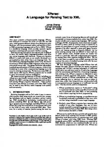
Graphs are a general means to represent any kind of data structures. Especially, they are well-suited to show the structure of XML documents. Visualizing an XML document by a graph, it usually resembles a DOM tree and can be enhanced by edges which represent references to other identities, in addition. For an example, see Fig. 1 where part of a WebML document is visualized. If XML documents conform to a given DTD or XML Schema, this typing information can be represented by typed graphs. The DTD or XML Schema is translated to a type graph which looks similar to class diagrams (without
Fig. 1. Graph which represents the example WebML document in Section 2
additional constraints). As in object-oriented modelling, types can be structured by an inheritance relation [6]. Instances of a type graph are structure graphs equipped with a structure-compatible mapping to the type graph. Formally, structure graphs are described by typed attributed graphs [7]. An attribute is declared just like a variable in a conventional programming language: we specify a name and a certain type for the attribute, and then we may assign any value of the specified type to it. All graph objects of the same type also share their attribute declarations, i.e. the list of attribute types and names; only the values of the attributes may be chosen individually. From a conceptual point of view, attribute declarations have to be considered as an integral part of the definition of a type. In theory [7], the attribute values are defined by separate data nodes which are elements of some algebra. In the AGG [1] tool, the attribution is based on Java (see below). A graph transformation rule r : L → R consists of a pair of T -typed graphs L, R such that the union L∪R is defined. In this case, L∪R forms a graph again, i.e. the union is compatible with source, target and type settings. The left-hand side L represents the pre-conditions of the rule, while the right-hand side R describes the post-conditions. L ∩ R defines a graph part which has to exist to apply the rule, but which is not changed. L \ (L ∩ R) defines the part which shall be deleted, and R\(L∩R) defines the part to be created. To make sure that newly created items are not already in the graph, we have to generate new vertex and edge identifiers whenever a rule is applied. Formally, for each application a new rule instance is created. Furthermore, a rule may specify attribute computations.
For this purpose, the rule graphs can be attributed by elements of term algebras which are instantiated by concrete values in the graphs when the rule is applied. Two sample rules are given in Figures 3 and 5, created with AGG. Both figures show the LHS (left-hand side) L and RHS (right-hand side) R separately. All elements of (L ∩ R) are numbered correspondingly in L and R. Both rules do not delete anything, thus all elements in the LHS are numbered. The nonnumbered elements in the RHS are the elements to be created. Both rules use a lot of variables as attribute values which indicates that arbitrary values are allowed. If several attributes have the same variable as value, the corresponding matched values in the host graph have to be equal. This is the case, e.g. in the rule in Figure 5 where attribute xmi.id of node 14:UML:Class has the same variable as value as node attribute participant in node 4:UML:AssociationEnd. A graph transformation step is defined by first finding a match m of the left-hand side L in the current host graph G such that m is structure-preserving and type compatible. If a vertex embedded into the context, shall be deleted, dangling edges can occur. These are edges which would not have a source or target vertex after rule application. There are mainly two ways to handle this problem: either the rule is not applied at match m, or it is applied and all dangling edges are also deleted. The applicability of a rule can be further restricted, if additional application conditions have to be satisfied. A special kind of application conditions are negative application conditions which are pre-conditions prohibiting certain graph parts. Performing a graph transformation step with rule r at match m, all the vertices and edges which are matched by L \ (L ∩ R) are removed from G. The removed part is not a graph in general, but the remaining structure D := G \ m(L \ (L ∩ R)) still has to be a legal graph, i.e., no edges should be left dangling. This means if dangling edges occur during a rule application, they have to be deleted in addition. In the second step of a graph transformation, graph D is glued with R \ (L ∩ R) to obtain the derived graph H. Since L and R can overlap in a common graph, its match occurs in the original graph G and is not deleted in the first step, i.e. it also occurs in the intermediate graph D. For gluing newly created vertices and edges into D, graph L ∩ R is used. It defines the gluing items at which R is inserted into D. A graph transformation, more precisely a graph transformation sequence, consists of zero or more graph transformation steps. Given a host graph and a set of graph rules, two kinds of non-determinism can occur: first several rules might be applicable and one of them is chosen arbitrarily. Second, given a certain rule several matches might be possible and one of them has to be chosen. There are techniques to restrict both kinds of choices. Some kind of control flow on rules can be defined by applying them in a certain order or using explicit control constructs, priorities, etc. Moreover, the choice of matches can be restricted by specifying partial matches using input parameters. A common form of controlled rule application is the following one: One rule is selected from outside (e.g. the user) and triggers the application of
a number of other rules which become applicable after the first rule has been applied. The graph transformation approach presented is supported by AGG [1] which is an integrated development tool for typed attributed graph transformation, implemented in Java. It offers the visual development of graph transformation systems including visual editing and simulation as well as a number of validation tools. The internal graph transformation engine can also be used by a Java API and thus, can be integrated into other tool environments. Several XML based input and output formats are available to the integration of AGG with other tools.
4
The Graph-based Approach
The approach we propose aims at simplifying the process by letting the developer design the transformation visually and abstracting from document structure and element production order. Relation between XML Documents and AGG Graphs To be able to use graph transformation for the transformation of XML documents, there must be translations between XML documents and graphs. A simple solution is to provide universal XSL transformations from XML documents (without DTD or XMLSchema) to AGG graphs in the proprietary XML format for AGG, GGX, and back from GGX to XML. Once provided the user can completely concentrate on graph transformation and does not have to deal with XSL transformations at all. This idea can be extended to XML documents which conform to a DTD or XML Schema. In this case, the universal XSL transformation also transforms the DTD or XML Schema into a corresponding type graph. In this case the type graph may be enhanced by stronger constraints such as multiplicities. These XSL transformations are applicable to any XML documents. A resulting AGG graph shows the structure of the corresponding XML document and resembles a DOM tree enhanced by additional edges which represent references to other identities. The translation between XML documents and AGG graphs can also be obtained on the basis of a Java API for AGG which can be used to construct and read graphs. XML Transformation by Graph Transformation Describing an XML transformation by graph transformation, the source and target documents are visualized by graphs as discussed above. Performing XML transformation by graph transformation means to take the structure graph of an XML source document, and to transform it according to certain transformation rules. The result is the structure graph of the XML target document. An XML transformation can be precisely defined by a graph transformation system GT S = (T, R) consisting of a type graph T and a set of transformation rules R. The structure graphs of the source documents can be specified by a
subset of instance graphs over a type graph TS . Correspondingly, the structure graphs of the target documents are specified by a subset of instance graphs over a type graph TT . Both type graphs TS and TT have to be subgraphs of the common type graph T . See Figure 2. Starting the XML transformation with instance graph GS typed over TS , it is also typed over T . During the transformation process, the intermediate graphs are typed over T . Please note that this type graph may contain not only TS and TT , but also additional types and relations which are needed for the transformation process only. The result graph GT is automatically typed over T . If it is also typed over TT , it fulfills the requirement to be valid. incT /T o TTO = O aDD z DD z z DD zz DD type zz typeG DD GT S zz typeGi typeS typeT DD z z DD zz D z DD zz D zz ri rj rk rl +3 Gi +3 ... +3 ... +3 GT GS
TOS
incS
Fig. 2. Typing in the transformation process
5
Example: From XMI to WebML
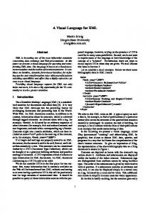
In this section, we take up the running example again and show how graph transformation can be used to transform UML class diagrams in XMI format into entity-relationship diagrams in WebML. The type graph for the transformation consists of three parts. Figure 4 shows the main section of type graph. The left part represents the type graph for WebML structures. The right part shows the type graph for XMI structures. In the middle, is one node type transf for relating XML nodes in both structures. The transformation system contains five rules connecting nodes of the XMI document to newly created nodes in the WebML document (one rule for each element in the target document). Rules are quite simple and generally map a set of nodes (XMI is particularly verbose) into a target document node. Figure 3 shows the rule converting a class node into an entity node. The left hand side matches a UML:Class node child of a UML:Namespace.ownedElement, the latter has already been translated into a Structure element to which it is connected by a transf node and two edges. The RHS of the rule adds a new entity, connects it to the parent node with a child edge, and to the originating UML:Class node via a transf node and edges. Since this transformation should be performed only once for each class, the rule is equipped with a negative application condition which is structurally equal to the RHS. That means before inserting a new entity for some class, we check that this class is not already related to some entity. This
visual approach simplifies the design of the transformation giving the user a clear representation of what each rule will produce.
Fig. 3. Graph rule which translates classes to entities
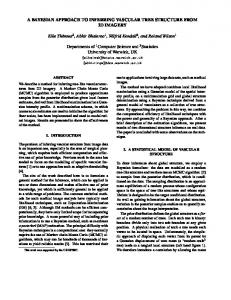
The rule in Figure 5 is used to create two relationship nodes starting from a UML:Association subtree. In LHS, we search for a pattern consisting of an association with association ends which refer to the participating classes by attribute participant in UML:AssociationEnd nodes. The references are enforced by variables part1 and part2, to be matched with class IDs. Please note that this rule inserts two relationships, i.e. translates the association completely in one step, something not achievable in XSLT. Moreover, the use of variables to resolve IDREFs makes the rule clear at first sight. Again, this rule has a negative application condition structurally equal to the RHS, which prevents the rule from being applied twice to the same association. In addition to the example presented here, we successfully experimented our approach also in transforming XML graph representation into Scalable Vector Graphics (SVG), rendering XML documents in HTML and reverse, performing WebML model to Struts configuration files transformation. We report on these experiments as examples for graph transformation applications on the AGG home page [1]. Discussion The advantages of using graph rules instead of an XSLT transformation are multiple: first of all the result graph is typed, therefore enforcing the validity of the output with respect to the target document schema. This can be obtained in XSLT only by using schema-aware processors. Second, the representation of the type graph allows for an easier visual definition of the rules by matching subtrees, rule application conditions and behaviour are evident at first sight. Third, the use of variables (or edges) to deal with IDREFs is much more straightforward than any other construct in XSLT as we don’t have to look for elements considering current context but we can naturally compose chains of IDREFs without having to declare multiple keys or complex (context-dependent) navigation XPATHs. The disadvantages of using graph transformations reside in the fact that in general the matching of the LHS of a rule in an instance graph is NP-complete, and basic graph transformation systems don’t have a ”natural” way of expressing a sequence of execution. But more elaborated forms of graph
Fig. 4. Type graph of XMI to WebML transformation
transformation systems provide different kinds of control on rule applications, as e.g. execution layers, priorities, control flows, etc. Some powerful constructs could also be inspired by XSLT (e.g. implicit and explicit rule priorities) or the new XSLT2 proposal [17], such as the ”xsl:next-match” instruction.
Fig. 5. Graph rule which translates associations to relations
6
Reversal of XML Transformations
Automatic Reversal of Graph-Based XML Transformations Due to the fact that they are at a higher level of abstraction, graph-based XML transformations are
composed of rules that do not depend on the parsing order of the source document or order of nesting of the output. For this reason, under certain conditions, they can be automatically reversed to produce the inverse transformation, that is from the target document structure to the source one: this is not achievable with XSLT where each transformation is inherently uni-directional. Obviously, to be fully reversible, a transformation would need to be information lossless: alas, this is not the case in most real applications where target documents simply do not require some data. Anyhow, the proposed approach is able to provide a reverse transformation as close as possible. Moreover, once a transformation is performed, the result graph preserves information about elements related by the transformation. The graph rules performing the reverse transformation are based on the same type graph as the original rules, no changes are needed. The first observation when reversing rules is that all XML transformation rules we used are nondeleting: they only add elements. All transformation rules have a context which contains a relation between source and target elements already established. This context is preserved in forward and backward transformation rules. In addition, the LHS of the forward rule contains some source part, while the backward rule contains some target part. As RHS of the backward rule we take the RHS of the forward rule. It remains almost unaltered as it represents the completed relation between the source document and the target one. The computation of attribute values is inverted accordingly, with slight differences: Each attribute of a new element in a RHS must be provided with an initial value. If an attribute values cannot be restored, a default value has to be used. If target attributes are computed by functions on source attributes, in the reverse RHS, source attributes are calculated by inverse functions on target attributes. Example: From WebML to XMI This example shows one of the rules automatically obtained by inverting our example rules given in Section 5. Figure 6 shows the rule transforming an entity into a class, being the inverse rule of the one in Figure 3. The RHS of the rule is obtained from the original RHS by defining attributes of source document elements in terms (or functions) of target document attributes. As not all Class attributes are preserved in the WebML representation, just those attribute values that can be retrieved are used, therefore some Class attributes are left empty. Attribute values which were left empty in the Entity element of the original rule are discarded. The LHS is derived from the new RHS by deleting the new ”transf” node and all the source document elements that were connected to it (and to no other ”transf” node).
7
Related Work and Conclusion
Even though XSLT is a popular and well supported XML transformation language, other approaches might be better suited to perform some kind of transformations (or might better suit personal tastes). In the current paper we proposed a graph based approach that simplifies the specification of XML document
Fig. 6. Graph rule which translates entities to classes
transformations with respect to XSLT by being visual and independent of node writing order, by providing a ”natural” way to deal with IDREFs and by allowing for a unique specification for bi-directional transformation. This makes the proposed solution especially suitable for the OMG’s MDA methodology. We developed a prototype implementation of the approach based on AGG. Different proposals exist for using visual approaches to query, perform syntaxchecking, infer DTDs and schemas, and transform XML documents. XML-GL [5] uses graphs both for representing XML documents and queries on them, but it does not perform document transformation between different vocabularies. XQBE (XQuery by example [4]) provides a visual language to specify queries on XML documents and translates it into XQuery or XSLT. VXT [10] is a visual methodology to specify uni-directional XML document transformation, while XMLTrans [19] is a Java based transformation language. Xing [8] is a visual language to query XML documents. In [2] a graph grammar for inferring the DTD of an XML document is proposed. In [20] and [21] the authors use a context-sensitive graph grammar for both defining the schema of an XML document and the rules to translate it into another vocabulary. Bezivin et.al. [3] propose a model transformation approach to obtain tool interoperability in the context of certain applications. This approach shows some similarities to ours in the sense that it is based on EMF models and uses a more abstract transformation approach which is QVT-like [12]. Apart from using a different formalism w.r.t. other approaches our proposal performs DTD inference when needed, XML document transformation between different vocabularies with advantages w.r.t. XSLT regarding typing, visual matching and IDREFs, plus it allows reverse transformations. Future work will deal with performance issues and focus specifically on formalizing the requirements for a transformation to be fully reversible.
References 1. AGG Homepage. http://tfs.cs.tu-berlin.de/agg. 2. L. Baresi, E. Quintarelli. Graph transformation to infer schemata from XML documents. In Proceedings of the 2005 ACM symposium on Applied computing, pages 642 - 646, ACM Press, 2005 3. J. Bezivin, H. Bruneliere, F. Jouault, I. Kurtev. Model Engineering Support for Tool Interoperability. In Proceedings of 4th Workshop in Software Model Engi-
4.
5.
6.
7.
8. 9. 10.
11. 12. 13. 14. 15. 16. 17. 18. 19.
20. 21.
neering at 8th Int. Conf. on Model Driven Engineering Languages and Systems, 2005. D. Braga, A. Campi, S. Ceri. XQBE (XQuery by Example): a visual interface to the standard XML query language. ACM Transaction On Database Systems TODS, June 2005 S. Ceri, S. Comai, E. Damiani, P. Fraternali, S. Paraboschi, L. Tanca. XML-GL: A Graphical Language for Querying and Reshaping XML Documents. In Proc. of the Int. World Wide Web Conference, Canada, 1999 R. Bardohl, H. Ehrig, J. de Lara, and G. Taentzer. Integrating Meta Modelling Aspects with Graph Transformation for Efficient Visual Language Definition and Model Manipulation. In M. Wermelinger and T. Margaria, editors, Proceedings of FASE 2004, pages 214–228, 2004. H. Ehrig, U. Prange, and G. Taentzer. Fundamental Theory for Typed Attributed Graph Transformation. In H. Ehrig, G. Engels, F. Parisi-Presicce, and G. Rozenberg, editors, Proceedings of ICGT 2004, volume 3256 of LNCS, pages 161–177. Springer, 2004. M. Erwig. Xing: A Visual XML Query Language. In Journal of Visual Languages and Computing, 14(1):5– 45, 2003 D. Novatchev. The Functional Programming Language XSLT - A proof through examples. http://www.topxml.com/xsl/articles/fp/ Nov. 2001 E. Pietriga, J. Vion-Dury, V. Quint. VXT: a visual approach to XML transformations. In Proceedings of the 2001 ACM Symposium on Document engineering, pages 1–10, ACM Press, 2001 SGML, http://www.w3.org/MarkUp/SGML/ Query/View/Transformation. QVT-Merge Group, version 2.0 (2005-03-02), 2005. http://www.omg.org/cgi-bin/apps/doc?ad/05-03-02.pdf WebML, http://www.webml.org/ XML, http://www.w3.org/XML/ XPath, http://www.w3.org/TR/xpath XSLT, http://www.w3.org/TR/xslt XSLT 2.0, http://www.w3.org/TR/xslt20/ XMI, http://www.omg.org/technology/documents/formal/xmi.htm D. Walker, D. Petitpierre, S. Armstrong. XMLTrans: a Java-based XML transformation language for structured data. In Proceedings of the 18th conference on Computational linguistics - Volume 2 pages 1136 - 1140, 2000 K. Zhang, D. Zhang. XML Transformations Through Graph Grammars IEEE International Conference on Multimedia and Expo, 2001. K. Zhang, D. Zhang, Y. Deng. A Visual Approach to XML Document Design and Transformation. IEEE Symposium on Human Centric Computing Languages and Environments, 2001.