IEEE MICROWAVE AND WIRELESS COMPONENTS LETTERS, VOL. 24, NO. 6, JUNE 2014
421
A Graphical Aid for the Complex Permittivity Measurement at Microwave and Millimeter Wavelengths Mário G. Silveirinha, Senior Member, IEEE, Carlos A. Fernandes, Senior Member, IEEE, and Jorge R. Costa, Senior Member, IEEE Abstract—We introduce a novel procedure to retrieve the comof dielectric materials. It is a variant of plex permittivity the well-known waveguide method, and uses as input the one-port reflection data from a vector network analyzer connected to a shortcircuited rectangular waveguide filled with a dielectric sample of known length. Here, it is shown that for low to moderate loss materials, the locus of the reflection coefficient in the complex plane versus frequency is approximately a circumference arc with curvature radius that depends mainly on and such that the swept angle depends mostly on . It is proven that fitting the theoretical circumference arc with the measured data not only allows identifying possible measurement errors but also enables estimating the complex permittivity with good accuracy. A graphical based implementation of the method is described and validated experimentally. Index Terms—Measurement of complex dielectric permittivity, microwave and millimeter wave measurements, waveguide graphical method.
T
I. INTRODUCTION
HE knowledge of the complex permittivity of a dielectric material is of key importance for the design of microwave and millimeter-wave components, such as printed circuits, filters, and antennas. For the past two decades, the authors have been working on dielectric lens antennas [1]. An accurate antenna design and characterization requires a precise knowledge of the material complex permittivity within the operating frequency band. For lens antennas applications, it is also essential to confirm that the dielectric material is to a good approximation isotropic and homogeneous before the lens fabrication. Typical materials used in dielectric lenses have low to moderate permittivity, , and loss values of the order of . There are several well-known techniques for the measurement of the complex permittivity at microwaves and millimeter-waves. A very complete revision is presented in [2]. The waveguide based method allows using smaller size samples than open air methods. This is quite useful because it permits cutting Manuscript received September 23, 2013; revised November 29, 2013; accepted February 26, 2014. Date of publication March 24, 2014; date of current version June 03, 2014. This work was supported in part by the Fundação para a Ciência e Tecnologia under Project mm-SatComPTDC/EEI-TEL/0805/2012. M. G. Silveirinha is with the Department of Electrical Engineering, Instituto de Telecomunicações, University of Coimbra, Coimbra 3030, Portugal (e-mail:
[email protected]). C. A. Fernandes is with the Instituto de Telecomunicações, IST, Lisboa 1049001, Portugal. J. R. Costa is with the Instituto de Telecomunicações, IST, Lisboa 1049-001, Portugal and also with the Departamento de Ciências e Tecnologias da Informação, Instituto Universitário de Lisboa (ISCTE-IUL), Lisboa 1649-026, Portugal. Color versions of one or more of the figures in this letter are available online at http://ieeexplore.ieee.org. Digital Object Identifier 10.1109/LMWC.2014.2310470
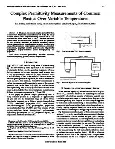
Fig. 1. Experimental setup (open view).
samples from different parts of the bulk material, eventually with different orientations, and investigate the homogeneity and isotropy of the material. Here we propose a graphical based approach that allows measuring the complex permittivity of a material and quickly diagnoses the occurrence of common sources of error such as relatively wide air gaps or a misplacement of the sample. These imperfections can be detected during the course of measurements, allowing immediate corrective actions. The method allows for an unambiguous determination of the complex permittivity from a single material sample. II. FORMULATION The experimental setup is shown in Fig. 1. The single mode waveguide operation is assumed. The dimensions of the waveguide cross-section are in the H-plane, and in the E-plane. The sample under-test is non-magnetic and assumed non-dispersive within the frequency band of interest. For now, it is supposed that the sample with length completely fills the waveguide cross-section, without air-gaps. The rectangular waveguide is terminated with a short circuit. A vector network analyzer (VNA) is used to obtain the reflection coefficient plane, as the frequency is swept in the referred to the , where is the central interval is the frequency span. frequency and is calculated with transmisThe reflection coefficient at sion line theory. The waveguide transverse impedance in air ) or in the dielectric is given by (subscript (1) where
is the longitudinal wave number in each medium (2)
The reflection coefficient at the dielectric side of the interface is
1531-1309 © 2014 IEEE. Personal use is permitted, but republication/redistribution requires IEEE permission. See http://www.ieee.org/publications_standards/publications/rights/index.html for more information.
(3)
422
IEEE MICROWAVE AND WIRELESS COMPONENTS LETTERS, VOL. 24, NO. 6, JUNE 2014
Consistent with these results it can be checked that written as
can be (12)
where the phase
is given by (13)
Fig. 2. Locus of the reflection coefficient from to 65 GHz on the Smith Chart (or complex plane) for different permittivity values of a sample with in a waveguide with width : (a) reflection coefficient at the dielectric side of the interface; (b) reflection coefficient at the interface. air side of the
On the other hand, the reflection coefficient , can be expressed in terms of of interface
at the air side as follows: (4)
The swept arc associated with frequency range as
,
, is related to the swept
(14) Thus, from the length (in radians) of the swept arc of circumference associated with the locus of , one can obtain a first estimate for the unknown permittivity by solving (14). Generally this equation has several solutions. The physical solution with the arc initial point. is extracted by comparing Once is known one can compute from (6), and then, from the radius , we can find
This can be rewritten in a more convenient way as
(15) (5) This result is easily obtained from (10). Finally a first approxiis found using mation for
where (6)
(16) For weak material loss, , and a small fre, (3) represents approximately a circumference quency span arc in the Smith Chart (or complex plane). This is confirmed in Fig. 2, for a set of simulated curves in the frequency interval . Next, we note that the derivative of the parameter with frequency is (7) But typically we have (8) hence, may be considered approximately constant within the swept frequency band. Within this assumption the reflection coefficient given by (5) is a bilinear (Möbius) transformation (9) and complex constants. It is with well known that this transformation maps circles and lines into lies circles and lines [3]. Thus, because in case of low loss in a circumference centered at the origin, we conclude that is mapped by (5) into another circumference with radius (10) and whose center is shifted away from the origin to (11) Calculated examples are presented in Fig. 2.
III. EXAMPLE OF APPLICATION This section describes the application of the method to the determination of the complex permittivity of Polyethylene in . the interval A V-band rectangular waveguide receptacle with nominal di, and length mensions was fabricated and terminated with a short-circuit. A calibration procedure is used to accurately determine the actual values of and . This calibration involves the measurement of the reinterface flection coefficient of the empty receptacle at the for the frequency span of interest. An optimization procedure is used to fit the measured data (circumference in the Smith Chart) and with (3). In the present example, this yields . The Polyethylene sample is then placed inside the sample is measured for this setup. The locus of the exholder, and perimental data in the complex plane is shown in Fig. 3. Using a standard least square minimization one can find the circumference that best fits the measured data. It is found that it is centered , that the radius is at and that the swept arc is radians. Desirably, the must be such length of the sample and the frequency span that the measured arc amplitude is larger than 180 in order to reduce the estimation error in the fitting process. . Using(14) and (16), it is found that This first guess value is then fed to an optimizing routine that finds the best fit between the experimental data and the theoretical model from (5). The optimization goal is to minimize the squared distance between measured data and the theoretical . The use model (5). This refinement gives
SILVEIRINHA et al.: A GRAPHICAL AID FOR THE COMPLEX PERMITTIVITY MEASUREMENT AT MICROWAVE AND MILLIMETER WAVELENGTHS
Fig. 3. Locus of the measured reflection coefficient of a Polyethylene sample from to 65 GHz on the Smith Chart. with length
423
. Equation (17) can be where numerically solved with respect to . A particularly interesting feature of our graphical method is that the presence of air gaps or other perturbations (e.g., a misplaced sample or an imperfect short-circuit termination) can be detected during the measurements. In fact, air gaps originate hybrid or high order modes in the sample holder. Theses modes introduce perturbations in the measured reflection coefficient that are manifested as ripples, curls or deviations from the expected circumference representation. In order to exemplify this behavior two simulations were performed in CST Microwave Studio [8] (Fig. 4) for a MACOR sample ( ) with and without an air gap in the E-plane of . For the case without air gap the proposed graphical method , while in the presence gives the permittivity gap the method gives . of the Using (17) one can eliminate the influence of the air gap, and . this yields V. DISCUSSION
Fig. 4. Locus of the simulated reflection coefficient of a MACOR™ sample from to 65 GHz on the Smith Chart, with and with length air gap adjacent to the top wall of the waveguide. without a
of curve fitting methods to determine dielectric properties with waveguide measurements has been considered in other works [4], but the novelty of our approach is that it allows obtaining a quite accurate first estimate for the permittivity from the swept arc length and curvature radius in the Smith chart. In this example the error in the initial estimate of the real part of the permittivity is less than 0.2%. In order to validate the proposed method, a disk sample from the same Polyethylene batch was cut, with a diameter and thickness and its complex permittivity was measured using the open resonator method Fabry-Perot [5]. The obtained complex permittivity value is [6]. The mismatch in the imaginary parts of the measured permittivities is larger than for the real parts, because it is difficult to measure very precisely (with any method) in case of very low loss materials. IV. INFLUENCE OF AIR GAPS It is well known that air-gaps, mainly in the E-plane where the E-field is the stronger, can introduce considerable error in the complex permittivity estimation [2]. This error decreases with the permittivity value of the material [7]. A solution for this problem is to apply a conducting paste to the edges of the can be sample [7]. Alternatively, if the height of the gap measured and is known, it is possible to relate the “correct” as [2] with the measured value complex permittivity
(17)
The proposed method is a simple graphic fitting procedure and yet it has several advantages. Since it is a waveguide based method it only requires small samples. The samples can be cut from different locations of the material batch and used to evaluate its homogeneity and anisotropy. The method is not plagued with multiple solutions that require the measurement of multiple samples. Most importantly, during the measurement procedure it is simple to identify errors and perturbations such as the misplacement of the sample or air gaps. Therefore, a simple visual inspection of the data representation in the Smith Chart allows for a first validation and, if needed, an adequate correction of the measurement procedure, even before the post-processing of the measured data and the calculation of the complex permittivity. ACKNOWLEDGMENT The authors wish to thank V. Fred for prototype construction, A. Almeida for prototype measurements, and J. Almeida for initial developments. REFERENCES [1] C. A. Fernandes, E. B. Lima, and J. R. Costa, “Broadband integrated lens for illuminating reflector antenna with constant aperture efficiency,” IEEE Trans. Antennas Propag., vol. 58, no. 12, pp. 3805–3813, Dec. 2010. [2] L. F. Chen, C. K. Ong, C. P. Neo, V. V. Varadan, and V. K. Varadan, Microwave electronics: Measurement and materials characterization. New York: Wiley, 2004, ch. 4. [3] R. Churchill, Complex variables and applications. New York: McGraw-Hill, 1984. [4] S. Khanal, T. Kiuru, J. Mallat, O. Luukkonen, and A. V. Räisänen, “Measurement of dielectric properties at 75–325 ghz using a vector network analyzer and full-wave simulator,” Radioeng. J., vol. 21, no. 2, pp. 551–556, 2012. [5] T. M. Hirvonen, P. Vainikainen, A. Lozowski, and A. V. Raisanen, “Measurement of dielectrics at 100 ghz with an open resonator connected to a network analyzer,” IEEE Trans. Instrum. Meas., vol. 45, no. 4, pp. 780–786, Aug. 1996. [6] C. A. Fernandes and J. R. Costa, “Permittivity measurement and anisotropy evaluation of dielectric materials at millimeter-waves,” in Proc IMEKO World Congress, Lisboa, Portugal, Sep. 2009, pp. 673–677. [7] S. B. Wilson, “Modal analysis of the ‘Gap effect’ in waveguide dielectric measurements,” IEEE Trans. Microw. Theory Tech., vol. 36, no. 4, pp. 752–756, Apr. 1988. [8] CST [Online]. Available: www.cst.com