MORPHOLOGICAL COMBINATORY TOOL FOR DESIGN OF LOW GAP AUTOMOTIVE BODY PANELS Clemson University, Clemson, SC -29631 BMW Manufacturing Co.,Spartanburg,SC Sudhakar Teegavarapu (
[email protected]) Andreas Obieglo Prabhu Shankar (
[email protected]) Ajit Kanda (
[email protected]) Beshoy Morkos (
[email protected]) Ashwin Michaelraj (
[email protected]) Joshua D Summers(
[email protected])
SAE Congress 2009, Detroit on 03/21/2009
Automation in Design Lab, Mechanical Engineering Dept http://aid.ces.clemson.edu
System Integration Tool
OUTLINE
Introduction Motivation System Integration Framework System Integration Chart Conclusion
http://aid.ces.clemson.edu
[email protected]
2/22 2009.03.21
System Integration Tool
INTRODUCTION
• Tolerance stack up in all parts and assembly due to design, manufacturing and assembly methods leads to gap in
body panel • Gaps affect customer perception • Low uniform gap between panels provide better noise sealing and aesthetics • Existing
CAD
tools
helps
analyze
clearances quantitatively • Lack of design tools to develop concepts
and analyze qualitatively
http://aid.ces.clemson.edu
[email protected]
3/22 2009.03.21
System Integration Tool
OUTLINE
Introduction Motivation System Integration Framework System Integration Chart Conclusion
http://aid.ces.clemson.edu
[email protected]
4/22 2009.03.21
System Integration Tool
MOTIVATION
5/22 2009.03.21
• A BMW funded project to develop concepts to reduce gap between headlamps and the adjacent body panels • To identify causes for higher gaps between body panels and the other
exterior components
http://aid.ces.clemson.edu
[email protected]
System Integration Tool
•
BENCHMARK STUDY
6/22 2009.03.21
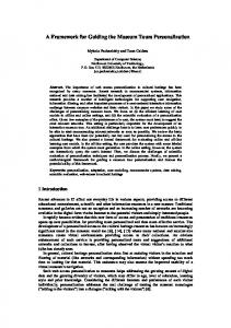
Objective of the study was to measure the gap
Moving Interface
between the headlamp and the body panel
Static
• 64 passenger cars involving 24 different brands
Interface
were benchmarked • Study revealed that higher gaps between the body
panels and headlamp can be due to (i)
Straight
Type of interface
Interface
- Higher the components higher the gap Curved
(ii)
Shape of the panels
Interface
- Straight edge interface has lower gap compared to curved interface (iii)
Edges (no.)
Assembly methods
4
- Bolts, threaded joints results in larger gap
3.3 2.28
3.03
3.2 2.58
OEM 1
OEM 2
OEM 3
Gap (mm) 4.88
4.5 3.91
3.65
OEM 4
OEM 5
- Snap fit results in lower gap
http://aid.ces.clemson.edu
[email protected]
System Integration Tool
OUTLINE
Introduction Motivation System Integration Framework System Integration Chart Conclusion
http://aid.ces.clemson.edu
[email protected]
7/22 2009.03.21
System Integration Tool
SYSTEM INTEGRATION FRAMEWORK
Six step system integration framework : Identify the geometric integration objective
Identify the set of 'means' for the specific objective
Create the Geometric integration concept generation charts (GICGC)
Map concepts analysis
and perform qualitative
Select concepts and set the specification to the supplier (or) Verify the concepts received from the supplier against the GICGC , if they meet the geometric integration objective.
Concept freeze and move to the next stage of integration i.e. quantitative analysis using 3D CAD models
http://aid.ces.clemson.edu
[email protected]
8/22 2009.03.21
System Integration Tool
OUTLINE
Introduction Motivation System Integration Framework System Integration Chart Conclusion
http://aid.ces.clemson.edu
[email protected]
9/22 2009.03.21
System Integration Tool
MORPHOLOGICAL REPRESENTATION
10/22 2009.03.21
Traditional morphological chart lists means along rows for each function
HOOD
Headlam Cover p Shield Using Trim
Dimpling
Sealant
Backlite
Wrap Light Around
Simply Supported
Set In
Bumper
Cover using trim
Dimpling
Sealant
Backlite
Wrap light around
Simply supported
Set in
Fender
Cover using trim
Dimpling
Sealant
Backlite
Wrap light around
Simply supported
Set in
Grill
Cover using trim
Dimpling
Sealant
Backlite
Wrap light around
Simply supported
Set in
HeadLa mp Casing Frame
Cover using trim
Dimpling
Sealant
Backlite
Wrap light around
Simply supported
Set in
Cover using trim
Dimpling
Sealant
Backlite
Wrap light around
Simply supported
Set in
Radiator mount
Cover using trim
Dimpling
Sealant
Backlite
Wrap light around
Simply supported
Set in
Bumper mount
Cover using trim
Dimpling
Sealant
Backlite
Wrap light around
Simply supported
Set in
Module Mount Lower Module Mount Upper
Cover using trim
Dimpling
Sealant
Backlite
Wrap light around
Simply supported
Set in
Cover using trim
Dimpling
Sealant
Backlite
Wrap light around
Simply supported
Set in
http://aid.ces.clemson.edu
[email protected]
Interlocking / Overlaping Surface Interlocking / overlaping surface Interlocking / overlaping surface Interlocking / overlaping surface Interlocking / overlaping surface Interlocking / overlaping surface Interlocking / overlaping surface Interlocking / overlaping surface Interlocking / overlaping surface Interlocking / overlaping surface
Gasket
Adhesive Joint
Gasket
Adhesive joint
Gasket
Adhesive joint
Gasket
Adhesive joint
Gasket
Adhesive joint
Gasket
Adhesive joint
Gasket
Adhesive joint
Gasket
Adhesive joint
Gasket
Adhesive joint
Gasket
Adhesive joint
System Integration Tool
GEOMETRIC INTEGRATION CONCEPT GENERATION CHART (GICGC)
11/22 2009.03.21
Chart Construction Approach: • The part/assembly under study is placed at
Components visible from outside (A)
Means to manage gaps between components visible from outside (B)
the center of the table • The exterior part/ assembly is placed to the
headlamp exterior (C)
left of the table • The interior part/ Assembly is placed to the
L H S
means to connect exterior and the interior of the headlamp (D)
C E N T E R
right of the table headlamp interior (E)
• The ‘means’ of connection between the exterior components, interior components and the subject under study are placed
column wise immediately next to the respective components’ column http://aid.ces.clemson.edu
[email protected]
Means to assemble the interior components (F)
Structural components which are not visible from outside, but affect the final gap (G)
R H S
System Integration Tool
GEOMETRIC INTEGRATION CONCEPT GENERATION CHART (GICGC)
12/22 2009.03.21
Constructing the left hand side of the table : Components visible from outside (A)
Means to manage gaps between components visible from outside (B)
L H S
headlamp exterior (C)
means to connect exterior and the interior of the headlamp (D)
Repeat the pattern 'A' & 'B' towards left
Start from here
C E N T E R
headlamp interior (E)
A
B
Hood Bumper
Cover using trim Gasket Dimpling Project Over
Fender
Caulking
Grill
Backlit Wrap light around
A
B
Hood Bumpe r Fender
Cover using trim Gasket Dimpling Project Over Caulking
Grill
Backlit Wrap light around
A
B
Hood Bumpe r Fender
Cover using trim Gasket Dimpling Project Over Caulking
Grill
Backlit Wrap light around
A
B
Hood Bumper
Cover using trim Gasket Dimpling Project Over
Fender
Caulking
Grill
Backlit Wrap light around
http://aid.ces.clemson.edu
[email protected]
Means to assemble the interior components (F)
Structural components which are not visible from outside, but affect the final gap (G)
R H S
System Integration Tool
GEOMETRIC INTEGRATION CONCEPT GENERATION CHART (GICGC)
13/22 2009.03.21
Constructing the right hand side of the table:
F
Means to manage gaps between components visible from outside (B) G
F
Adhesive joint Threaded joint Snap Fits Circlips Welded joint
Frame
Adhesive joint Threaded joint Snap Fits Circlips Welded joint
Clamp joint
Radiator mount
Clamp joint
Shrink Fit
Bumper mount
Shrink Fit
Magnetic joint suction / vacuum joint Riveted joint Hook joint
Lower Fender mount Upper Fender mount
Magnetic joint suction / vacuum joint Riveted joint Hook joint
Interference fit joint Ball joint Universal joint
Components visible from outside (A)
REPEAT THE PATTERN ‘F' & ‘G' TOWARDS RIGHT
START FROM HERE
Grill mount Wheel housing cover
Interference fit joint Ball joint Universal joint
G
F
Frame
Adhesive joint Threaded joint Snap Fits Circlips Welded joint
Radiator mount Bumper mount Lower Fender mount Upper Fender mount Grill mount Wheel housing cover
Clamp joint Shrink Fit Magnetic joint suction / vacuum joint Riveted joint Hook joint
L H S
G
headlamp exterior (C)
means to connect exterior and the interior of the headlamp (D) Frame Radiator mount Bumper mount Lower Fender mount Upper Fender mount Grill mount Wheel housing cover
Interference fit joint Ball joint Universal joint
http://aid.ces.clemson.edu
[email protected]
C E N T E R
headlamp interior (E)
Means to assemble the interior components (F)
Structural components which are not visible from outside, but affect the final gap (G)
R H S
System Integration Tool
GEOMETRIC INTEGRATION CONCEPT GENERATION CHART (GICGC)
14/22 2009.03.21
Constructing the centre portion of the table: Components visible from outside (A)
Means to manage gaps between components visible from outside (B)
C
D Welded joint Clamp joint
E headlamp exterior (C)
means to connect exterior and the interior of the headlamp (D)
Shrink Fit
Headlamp shield
Magnetic joint suction / vaccum joint Riveted joint Hook joint Interference fit joint
L H S
Headlamp casing
http://aid.ces.clemson.edu
[email protected]
C E N T E R
headlamp interior (E)
Means to assemble the interior components (F)
Structural components which are not visible from outside, but affect the final gap (G)
R H S
System Integration Tool
GEOMETRIC INTEGRATION CONCEPT GENERATION CHART (GICGC)
Complete Chart:
http://aid.ces.clemson.edu
[email protected]
15/22 2009.03.21
System Integration Tool
GEOMETRIC INTEGRATION CONCEPT GENERATION CHART (GICGC)
Textual Representation & Reading Of The Chart:
•
Headlamp shield is projected over the bumper
• Headlamp shield is projected over the hood • Headlamp shield is projected over the fender • Headlamp shield is joined adhesively with headlamp casing
Graphical Representation of the concept:
• Connection means are textually represented in an exploded view of the components • Easy to visualize the concept than textual method • Cannot be used for generating concepts
http://aid.ces.clemson.edu
[email protected]
16/22 2009.03.21
System Integration Tool
GEOMETRIC INTEGRATION CONCEPT GENERATION CHART (GICGC)
ANALYSIS: • Finding the number of interfaces. • Number of arrows starting and ending in the cell yields the number of interface of that
component • Eg. Headlamp shield has four interface • Visualization of the gap build up • Sequential mapping of the component through ‘means ‘ focus the designer’s attention to realize the gap build up • Component dependency based on the directionality • Eg. The arrow pointing from Headlamp shield to Hood, bumper and fender represents its dependency on these components
http://aid.ces.clemson.edu
[email protected]
17/22 2009.03.21
COMPONENT INTERACTION CHART
System Integration Tool
18/22 2009.03.21
• Component interaction chart (CIC) is the second variation of the morphological chart • Less clustered chart
• Each instance of the chart has one component in a column, such as the
Exterior/ Visible Component Component Exterior Interaction Internal/Hidden Componet Interior Interactions
Exterior Component:Hood Interactions concerning the gaps
None Interlocking
hood, and its corresponding interacting components listed in an adjacent column. • The
interactions
between
the
main
component and the sub-components are
Set in
Hood
HeadLamp Sheild Bumper
Cover using trim Gasket
Fender
Dimpling
Grill
Overlapping Surface Sealant Backlite
mapped through the means. • Each component is analyzed individually
http://aid.ces.clemson.edu
[email protected]
Wrap light around Simply supported
System Integration Tool
Criteria
COMPARISON OF DIFFERENT REPRESENTATIONS GICGC chart
19/22 2009.03.21
Component interactions chart Morphological chart Both have same type of Both have same type of Simplicity representation, one to many. CIM is Simpler than GICGC and CIM representation, many to many GICGC done for individual parts. Focus is on components rather Relevant to analyze and develop an Relevance Relevant to generate new concepts than functions. Functions are existing concept not clearly defined. It represents all the components Components and their interactions and interactions in a single graph. Ease of use are broken down into small entities, Easy to use if properly defined Users should picture the whole making it simple to use concept. Readability Big chart, less readable Small groups of charts, easy to read easy to read Individual component interactions Ease of Concepts as a whole can be should be combined together to lead easy interpretation interpreted from the single chart to a concept Can be made exhaustive at the Exhaustive Exhaustive not exhaustive expense of readability Abstraction High level Medium level Very high level Potential to generate High Low Medium concepts Scope of analysis is high, such as direction of interactions, number of Analysis is restricted to type of Analysis interfaces, types of interfaces, and Offers no analysis interface possible source of tolerance stack up. Adaptability High Medium High http://aid.ces.clemson.edu
[email protected]
System Integration Tool
OUTLINE
Introduction Motivation System Integration Framework System Integration Chart Conclusion
http://aid.ces.clemson.edu
[email protected]
20/22 2009.03.21
System Integration Tool
CONCLUSION
A design tool is developed that aid the designer in the following: • Explore and force to think on various concepts • Visualize the assembly of components • Conduct qualitative analysis • Identify the possible sources of tolerance stack up contributors • Will serve as a ready reckoner for the system integrator
http://aid.ces.clemson.edu
[email protected]
21/22 2009.03.21
System Integration Tool
22/22 2009.03.21
THANK YOU
http://aid.ces.clemson.edu
[email protected]