A Hardware/Software Environment for Real-Time Data Acquisition and Control. A.L. Veiga, M.A. ... computer (PC) supporting several dedicated custom boards.
A Hardware/Software Environment for Real-Time Data Acquisition and Control A.L. Veiga, M.A. Mayosky1, N. Martínez1 UNLP, CC 69 (1900) La Plata, Argentina 1 CICPBA
Abstract A data acquisition framework based on a RT-Linux host and several embedded processors is presented. A Constant Velocity Mössbauer Spectrometer with controlled temperature sweep is shown as a real experimental application. The hardware platform consists of a standard personal computer (PC) supporting several dedicated custom boards. Each board has a microcontroller and additional hardware to interface with the experiment. A simple real-time kernel with a preemptive scheduling scheme was implemented for the microcontroller boards. Tasks are assigned to each standalone board during the initialization step. The PC runs the Linux operating system, with its real time extension RT-Linux [1]. The flow of data to and from the boards is implemented with real-time tasks through realtime FIFOs in an event-driven basis. The proposed structure dramatically simplifies the implementation of sophisticated user interfaces, using high level languages like Tcl/Tk or Java, for graphical and remote applications, without degrading real-time performance.
I. INTRODUCTION The fast evolution of the PC hardware and the diffusion of the local area networks (LANs) and the Internet have added new possibilities to the layout of experiments. The hardware required for remote control and data access, and for sophisticated graphical user interfaces (GUIs) is actually easy to get. However, the essential software required for commanding the whole experiment is far behind in this evolution. If some real-time performance is required for controlling the experiment (this is always the case when interacting with external hardware), there is a wide spectrum of real-time operating systems available in the market. These are, in general, expensive proprietary packages, difficult to expand. If POSIX functionality is also required, like normalized access to files, networks and GUIs, together with an open philosophy of development, the spectrum of possible systems turns very narrow. The proposed framework provides non real-time POSIX.1 functionality, without degrading the real-time characteristics of the system. The real-time performance is restricted to the low-level interaction with the hardware. Such structure is useful in a wide range of applications. It is implemented with a combination of Linux, RT-Linux and custom microcontroller-based embedded systems, preserving an open philosophy and availability of source code.
In the data acquisition scheme proposed, the custom boards run their own real-time tasks delivering to Linux a low rate of results and final data. The data is transferred in both directions using interrupt based RT-Linux real-time tasks (polling is strictly avoided). In addition, Linux is slightly loaded saving CPU resources for non time-critical tasks (e.g., display, network interface and data logging). This framework should not be considered as a full implementation of a real-time system. Real-time access to the hardware is guaranteed, but other resources, as network and file access are only available through a non real-time POSIX.1 interface within a time-sharing environment.
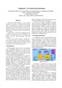
II. THE HARDWARE/SOFTWARE DATA ACQUISITION STRUCTURE The basic hardware for this implementation can be considered as standard: a 120 MHz Pentium based PC, with a hard disk, SVGA video interface and a 10 MHz network adapter. The microcontroller based EISA boards include one of the Intel 8051 family members, with a 20 MHz clock. For the implementation of a 16-bit EISA communication channel with the PC [2], two of the available 8-bit ports of the microcontroller are connected through latches to an I/O port of the PC. An interrupt is sent to the microcontroller whenever this port is addressed. The microcontroller interrupts the PC every time a message is ready, pulling an IRQ line of the bus using one output bit of a port. The other available resources of the microcontroller can be used for the specific application. In this paper, the actual implementation of a constant velocity Mössbauer experiment with controlled sweep of the sample is presented. Three boards were necessary to implement a PWM temperature control with a dual ramp 15 bits A/D converter, a programmable velocity reference and a counter. In the software structure proposed, as shown in Figure 1, three main components can be identified: the embedded realtime kernel for the boards, the RT-Linux interface, and the POSIX.1 Linux environment. These software components are described in detail in the following subsections.
A. Embedded Real-Time Kernel In order to handle several real-time tasks with the microcontrollers, a preemptive scheme was implemented using interrupt-based techniques [3], [4]. The Intel eight-bit microcontrollers have four available interrupts, and two of them can be associated to its internal timers. With an interrupt-based strategy, four independent real-time tasks can
be handled by each microcontroller, plus any number of non real-time tasks in the background. As the internal interrupt handling of the microcontroller only defines two levels of priority, some additional code was needed to provide a full preemptive scheduler for four tasks (four levels of interrupts are required). This code was programmed in assembler, in order to minimize the overhead associated with the scheduling and dispatching of the tasks. One of the real-time tasks is reserved for the communication between the other tasks and RT-Linux, through the EISA bus. Data Log Network POSIX.1 Linux Gui RT-Linux
Embedded uC System
Experiment
In order to characterize the real time behavior of these software components, a set of tests were designed to measure their interrupt response time and its ability to synchronize tasks. These tests are presented in the following section.
III. TESTING THE SOFTWARE COMPONENTS The three main components were tested in order to determine what could be expected from each of them. Since nowadays a standard performance test for real-time systems is not standardized [5], some practical tests were designed. If the tasks are grouped in synchronous and asynchronous, two basic questions need to be answered. For the first group of tasks, how accurately can a period be determined in order to synchronize a task? For asynchronous tasks, how fast can the component execute a task in response to an external event? Both aspects are analyzed for each component in the following subsections.
A. The Real-Time Kernel for the Boards Figure 1: Basic software structure proposed for the implementation of the experiment.
The intertask communication inside the microcontroller is implemented with shared memory. During the initialization step, the kernel receives a fixed set of tasks. Each task has a priority level assigned in the preemptive scheme. This priority can not be changed during run time. The group of tasks must be carefully designed in order to run with the highest independence as possible. This means that the group should be a compact set of tasks that requires a minimum communication with the rest of the system. This embedded scheme has an interrupt response time of about two microseconds, as is shown in the next section.
B. RT-Linux Interface The performance of this software package, also presented in the next section, proved to be quite satisfactory. The response time is bounded to 20 microseconds when interacting with the hardware. However, this response time might be too long for some applications. In our case, this package was reserved for the interaction between the microcontroller boards and the standard non real-time Linux tasks. Its FIFO based communication dramatically improves this point. It also provides a good way to set a communication channel between two microcontroller boards.
C. POSIX.1 Linux Environment The main duty of this software component is to provide the high level interfaces between the user and the experiment. The set of tasks assigned to Linux must be non time-critical, like data log and display, access to the network, etc.
For the microcontroller-based boards the first question is easy to answer: internal timers of the microcontroller can generate an interrupt with a resolution of one instruction period (12 times the clock period) at 20MHz [6]. That implies a minimum granularity of 12 times 1/20MHz = 0.6 microseconds for any computed time. It must be remembered that the internal timers of the microcontroller have only 16 bits (65536*0.6µsec=40msec). Therefore, some overhead will appear when working with longer periods because of the administration of the timer. To improve the response time to external interrupts, it is relevant that the real time kernel was programmed in assembler code. Since the source code is available, the interrupt latency time1 can be measured by simply counting the number of assembler instructions that the kernel requires for the scheduling and dispatching of the higher level task. Multiplying this number of instructions by the instruction period, we get an interrupt latency of two microseconds for the higher level task, including the context switch.
B. POSIX.1 Linux and RT-Linux The interrupt response time of the standard POSIX.1 Linux and RT-Linux were measured using a 2.0.29 kernel version on a 120MHz Pentium based PC. The standard kernel of Linux has a time-shared scheduling scheme, while RTLinux claims to have a preemptive one. To measure the interrupt latency a standard Centronics parallel port was used. For the RT-Linux test, the I/O ports and IRQ7 were handled by the real time tasks. In POSIX.1 Linux, the printer driver was modified applying standard techniques [7], in order to allow manipulation of the I/O ports and IRQ7 from a user’s program.
1 Time elapsed between the arrival of an interruption and the
execution of the first instruction of the associated task.
Two tests were run on each system. The synchronous test involved toggling one output bit of the parallel port every 20 milliseconds (minimum granularity of the POSIX Linux). The asynchronous test consisted in toggling the bit every time the IRQ7 was received. A Fluke 1953A Digital Counter Timer was used for the measurement. It provides a 0-125 MHz range and digital interface. Both tests were performed under different load conditions of the system, like intensive access to the hard drive or network adapter, intensive floating point calculation, or a combination of them. The main conclusions are presented here, while the whole experiment and resulting statistics can be found at http://www.fisica.unlp.edu.ar/rtlinux. In general terms, the POSIX.1 version of Linux and its device drivers show a good average behavior. However, the response time was, sporadically, as long as several milliseconds. This characteristic discards the utilization of Linux for the implementation of hard real-time systems. As expected, RT-Linux showed a bounded response time of about 20 microseconds. In Figure 2 some results are shown. The time elapsed between the arrival of an interrupt and the toggle of the output bit is presented for (a) POSIX.1 Linux and (b) RT-Linux systems.
Table 1 Interrupt response time in microseconds under heavy load System RT-Linux POSIX.1 Linux
Mean 4 369
a1
N
b1
1000
1000
100
100
RT-Linux is consistent with its specifications. The 20 milliseconds delay produced with the available real-time scheduler is confined to a 20 microseconds interval. N
a1
1000
N
b1
1000
100
100
σ =1.3 usec.
σ =46 usec. 10
10
1
1
16000 18000 20000 22000 24000 26000 28000 30000
19990
19995
usec.
20000
20005
20010
20015
usec.
a2
N
1000
1000
100
100
b2 σ =2.5 usec.
σ =539 usec.
σ =0.4 usec.
σ =312 usec. 10
Maximum 19 27546
The results for the second test are presented in Figure 3 and Table 2. For the standard Linux, the available POSIX.4 implementation of the nanosleep system call was used to postpone the execution for 20 milliseconds. The good average response is visible, but some occasional delays of several milliseconds discards its application for hard realtime systems.
N N
SD 1 528
10
10
10 1
1
1 0
5000
10000
15000
20000
25000
30000
5
usec.
10
15
20
a2
1000
b2
N 1000
100
100
σ =1.0 usec.
σ =528 usec. 10
10
1
1 5000
10000
15000
usec.
19990
usec.
19995
20000
20005
20010
20015
usec.
usec.
N
0
1
16000 18000 20000 22000 24000 26000 28000 30000 0
20000
25000
30000
0
5
10
15
20
usec.
Figure 2: Interrupt response time for both systems under different load conditions (where is the N number of events), (a1) unloaded POSIX.1 Linux, (a2) heavily loaded POSIX.1 Linux, (b1) unloaded RT-Linux, and (b2) heavily loaded RT-Linux.
The consequences of the system load are evident for POSIX.1 Linux. In the heavily loaded histogram, an isolated response time event of almost 30 milliseconds is present. The serious effect of the load is also evident in the average response time. On the other hand, RT-Linux appears more predictable. Its response time is bounded to 20 microseconds. However, it can be noticed that the average response time is not completely independent of the load condition. In Table 1, the mean, standard deviation (SD) and maximum response time for both systems are presented.
Figure 3: Generation of a time interval of 20 milliseconds for both systems under different load conditions (where is the N number of events), (a1) unloaded POSIX.1 Linux, (a2) heavily loaded POSIX.1 Linux, (b1) unloaded RT-Linux, and (b2) heavily loaded RT-Linux. Table 2 Time interval in microseconds under heavy load System RT-Linux POSIX.1 Linux
Mean 20009 19999
SD 2.5 539
Maximum 20016 29908
In order to provide an efficient design, this performance information is essential. However, it is also necessary to carefully study the possible distribution of the tasks between the available components.
IV. APPLICATION TO THE CONSTANT VELOCITY MÖSSBAUER EXPERIMENT A Constant Velocity Mössbauer Spectrometer [8] with controlled temperature sweep is shown as a real experimental application. A block diagram of the implementation is shown in Figure 4.
Heater
Detector
Embedded Temperat Control
Embedded Event Counter
RT-FIFO RT-FIFO RT-FIFO
POSIX.1 Linux Process
Drive
RT-Linux Process
Embedded Velocity Reference
Figure 4: Schematic implementation of the Mössbauer experiment.
Three microcontroller-based boards and a standard PC2 are used for the implementation. The temperature control of the sample is implemented with a board, which includes a discrete dual-ramp A/D converter [9], PID control algorithm, and PWM output. A second board provides the programmable velocity reference for the control of the source drive, and a third board implements the event counter.
and temperature display, and a panel to control the experiment. The Common Gateway Interface (CGI) extension of the HTML language was used to provide remote control and access to graphical data during run time. Alarms and relevant conditions are notified by e-mail to the operator through the Internet. It must be remembered that all this tasks are performed inside a POSIX.1 time-slice environment that may cause delays of several milliseconds in the execution of tasks. This implementation involves many different programmable hardware components and three different programming languages. This makes the initial implementation harder, but the modularity and reusability achieved simplifies future expansions and modifications of the experiment. Furthermore, the introduced modules are likely to be reusable for the implementation of other similar experiments.
V. ACKNOWLEDGMENTS
Each board delivers a low rate of data and receives configuration and parameters to and from a real-time task, in an interrupt-based scheme.
The authors thank Enrique Spinelli for his contribution in the testing phase of the different systems.
The real-time task communicates with POSIX.1 Linux and the boards. The real-time FIFOs avoid message loss. It also provides an adequate channel for passing data between different boards.
VI. REFERENCES
POSIX.1 Linux takes data from the FIFOs and performs only non real-time tasks (data logging and display, network interface and graphical user interface, including a control panel for the user). Two outstanding aspects of the distribution of tasks must be noticed in this application. The first one is that some tasks require response times that exceed the capacity of RT-Linux. For example, the discrete implementation of the dual-ramp A/D converter requires an accurate switching of the ramp. A straight implementation with RT-Linux is not feasible, because of the latency of this system (20 microseconds). It was necessary to use a microcontroller board (latency smaller that two microseconds) to handle this task. The second relevant aspect of design is that the utilization of RT-Linux (as an interface between POSIX Linux and the hardware) could not be avoided. The operation via POSIX device drivers was tried, resulting in sporadic lost of data. An adequate design of the groups of real-time tasks for the different modules results in a slight load of the CPU. That is because, in general terms, the hardware interaction in an interrupt-based scheme is not time-consuming. The remaining CPU time can be applied to perform non real-time tasks, without comprising the execution of the hard real-time tasks. For example, in this implementation, the Tcl/TK very high level programming language was used to provide an XWindows graphical interface, including on-line histograms 2 120MHz Pentium, 16MB RAM, 1GB HD, ethernet adapter,
and SVGA display.
[1] M. Barabanov and V. Yodaiken. “Introducing Real Time Linux”. Linux Journal, vol. 34, pp. 19-23. February 1997. See also http://www.rtlinux.org [2] L.C. Eggebrecht. “Interfacing to the IBM Personal Computer”. Macmillan Computing Publishing, 1991, pp. 89-128. [3] P.A. Laplante. “Real-Time Systems Design Analysis”. IEEE Press, 1992, pp. 145-152.
and
[4] G. Buttazzo. “Hard Real-Time Computing Systems, Predictable Scheduling Algorithms and Applications”. Kluwer Academic Publishers, 1997. [5] B.O. Gallmeister. “POSIX.4 Programming for the real world”. O’Reilly & Associates, 1995, pp. 251-275. [6] Intel Corp. MCS-51 Architectural Overview. “Hardware Description of the 8051 and 8052, MCS-51 Programmers Guide and Instruction Set y MCS-51 Data sheets”. 1983. [7] A. Rubini. “Linux Device Drivers”. O’Reilly & Associates, 1998. [8] T.E. Cranshaw. “Mössbauer Spectroscopy”. Journal of Physics E: Scientific Instruments, vol. 7, pp. 497-505, 1974. [9] E. Spinelli and A.L. Veiga. “Dual Slope A/D converter for the 8051”. Electronic Engineering, January 1996, p. 30.