2004 ACM Symposium on Applied Computing
A Hardware/Software Kernel for System on Chip Designs Andrew Morton
Wayne M. Loucks
Electrical and Computer Engineering University of Waterloo Waterloo, Ontario, Canada
Electrical and Computer Engineering University of Waterloo Waterloo, Ontario, Canada
[email protected]
[email protected]
ABSTRACT
project, the majority of the µITRON kernel functionality was implemented in a coprocessor called STRON-I [8]. Specifically, STRON-I implements the following:
As part of the SoC design process, the application is partitioned between implementation in hardware and implementation in software. While it is customarily the application that is subject to partitioning, it is also possible to partition the software kernel. In this paper, a uniprocessor real-time kernel that implements the Earliest Deadline First (EDF) scheduling policy is partitioned. It is partitioned by moving the EDF scheduler into a coprocessor. The coprocessor size and performance are analyzed. A metric is then proposed that measures a coprocessor’s impact on application feasibility. This metric permits a unified comparison of kernel coprocessors and application coprocessors during design partitioning.
• binary event flag, • counting semaphore, • timer, • task scheduling (fixed priority preemptive), • interrupt handling.
Keywords SoC, hardware/software codesign, operating systems
1.
INTRODUCTION
In the System on Chip (SoC) design paradigm, one or more CPUs is integrated with hardware coprocessors and other devices on a single integrated circuit. The hardware coprocessors implement a part of the application behaviour and work in cooperation with software executing on the CPU(s). To design an SoC, the designer must partition the application behaviour between software and hardware. While it is customarily the application that is subject to partitioning, it is also possible to partition the software kernel/operating system. In this paper, a uniprocessor realtime kernel that implements the Earliest Deadline First (EDF) [2] scheduling policy is partitioned between software and hardware. The coprocessor’s size and performance are analyzed. A metric is proposed that compares the relative benefit/cost of coprocessors (either application or kernel) in an SoC, which could be used to evaluate various hardware/software partitionings. Previous research efforts have investigated implementing real-time kernels almost entirely in hardware. In one such
Permission to make digital or hard copies of all or part of this work for personal or classroom use is granted without fee provided that copies are not made or distributed for profit or commercial advantage and that copies bear this notice and the full citation on the first page. To copy otherwise, to republish, to post on servers or to redistribute to lists, requires prior specific permission and/or a fee. SAC ’04 March 14-17, 2004, Nicosia, Cyprus Copyright 2004 ACM 1-58113-812-1/03/04 ...$5.00.
A software kernel is required to interact with STRON-I. The software kernel translates system requests into function codes and parameters that are written to STRON-I over the bus. STRON-I communicates with the CPU using interrupts and CPU-readable registers. As well as translating system requests, the software kernel is required to perform context switches when indicated by STRON-I. The resulting kernel is one third the size of the equivalent software-only kernel. The number of STRON-I resources (event flags, semaphores, timers) and the number of tasks is fixed at compile time. A prototype was implemented on a XC4010 Xilinx FPGA with 3 tasks, 3 event flags, 3 semaphores and 3 external interrupts, with a resulting size of 4300 gates and speed of 12 MHz. The coprocessor size scaled linearly with the number of tasks and resources. The kernel functions implemented in hardware were shown to be 6 to 50 times faster than the equivalent functions in software. The FASTCHART project [4] mated a custom CPU that could perform a context switch in one cycle with a kernel coprocessor called the RTU (Real Time Unit). The RTU shares several features with STRON-I including the communication method, priority preemptive scheduling and a number of kernel functions. In order to make the hardware kernel applicable to a broader range of applications, the RTU was extracted from FASTCHART so that it could be implemented as an ASIC. The RTU could then be interfaced with various real-time system buses, such as the VME bus [1]. A key difference with STRON-I is that the RTU can support multiple CPUs. The RTU has been commercialized as the UltraFast Micro Kernel (UFµK) [9]. UFµK implements the following functionality: • priority preemptive scheduling, • synchronization primitives (similar to event flags in STRON-I),
869
• task delay, • periodic task starts, • interrupt handler and • configurable bus interface. UFµK is supported on several FPGAs, allowing the number of tasks and resources to be configurable. Both the STRON-I and UFµK implement the majority of kernel functions in the coprocessor. A finer-grained partitioning of the kernel is investigated with the δ SoC/RTOS Codesign Framework [6]. The user can choose from a list of strategic parts of the Atalanta kernel to move into hardware. The list currently includes: 1. a lock cache for synchronization operations,
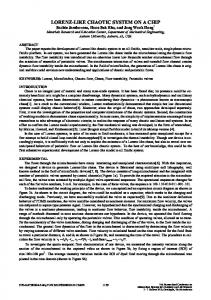
Figure 1: cs1 kernel
2. a deadlock detection unit for multi-processor systems and
a specified event occurs. All tasks are created at compile time. The cs1 kernel is designed to facilitate integration of hardware coprocessors into the software application. To integrate with the cs1 kernel, a coprocessor is required to have a software maskable interrupt and a status register that can be queried to determine interrupt status of the device. Two kernel resources are available to tasks: message objects and coprocessor objects. Aperiodic task releases are triggered by a received message or by a coprocessor interrupt. Tasks may block waiting on a message or a coprocessor interrupt. To implement EDF, the cs1 kernel maintains two lists sorted by deadline:
3. a dynamic memory manager. The goal is to achieve significant application speed-up using a small amount of hardware. In [3], the δ Framework was used to compare three kernel configurations: 1. software (Atalanta) 2. hardware/software (Atalanta with hardware lock cache) 3. hardware (RTU) The 3 configurations were simulated to implement a database application which required many task synchronizations. The hardware/software configuration had speed-ups of 1941% over the software, while the hardware configuration had speed-ups of 36-50% over the software. Synthesis of the lock cache required 7435 gates, while the RTU took approximately 250000 gates.
2.
1. run list - all tasks that are ready to execute 2. timer list - periodic tasks waiting to be released
KERNEL PARTITIONING
As described above, the δ Framework facilitates user-directed hardware/software partitioning of the kernel. In the work that follows, a uni-processor real-time kernel is partitioned by moving only the scheduler to hardware. First the softwareonly solution is introduced, followed by a description of the hardware scheduler implementation.
2.1
Software-Only Kernel
The run list and timer list are implemented with the minheap data structure which has log(n) insertion and removal time. (In addition to these 2 deadline-sorted lists, tasks that block on message send/receive or coprocessor setup/service calls are placed in FIFOs associated with the corresponding object.) The cs1 kernel can be invoked by: the currently executing task, an application coprocessor or the timer. The currently executing task causes the kernel to be invoked for one of three reasons: 1. it terminates
A software only kernel has been developed that is called “cs1” for CoScheduler1 [7]. The cs1 kernel executes on the 32-bit Nios CPU which can be implemented on a selection of Altera FPGAs. Unlike the research described above which scheduled by the fixed-priority preemptive policy, the cs1 kernel implements the Earliest Deadline First (EDF) scheduling policy. Under the preemptive EDF policy, of all ready tasks, the task with the earliest deadline is executed first. If another task arrives with an earlier deadline, it will preempt the currently executing task. EDF can achieve a higher processor utilization, in theory, than the fixed-priority policy [2]. The cs1 kernel, pictured in Figure 1, supports two task types: periodic and aperiodic. Periodic tasks are released at regular intervals, whereas aperiodic tasks are released when
2. it blocks on a message receive/send or a coprocessor setup/service 3. it unblocks another task by writing to a message queue.
2.2
Hardware/Software Kernel
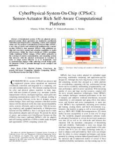
The cs1 kernel was manually partitioned to create the cs2 kernel. The application program interface (API) is the same for both kernels. The goal in partitioning was not to transfer the entire kernel into hardware but to choose a strategic part that would yield significant system speed-up with modest hardware overhead. It was decided to implement the EDF scheduling in a kernel coprocessor (referred to as the cs2 coprocessor in this paper). The design of the cs2 coprocessor is described in Section 3.
870
Figure 3: cs2 kernel interface). With the STRON-I and UFµK coprocessors, the number of tasks and resources are fixed at compile time. However the individual task parameters are programmed at run time (state, priority, etc). With the cs2 coprocessor, both the number of tasks and the task parameters are fixed at compile time. The reasons for this are as follows. • The cs2 coprocessor is mainly intended for SoPCs (System on Programmable Chip), meaning that the implementation target is an FPGA. Since the SoPC is reprogrammed for each application, the cs2 coprocessor doesn’t need to be generic.
Figure 2: cs1 kernel The cs1 and cs2 kernels are contrasted in Figures 2 and 3. These figures describe the activity of the kernels at each invocation. Those parts of cs1 that are not needed in cs2 appear in italics. Those parts of cs1 that are modified in cs2 are underlined. The main difference in the kernels is that the run-list and timer-list management of cs1 is replaced in cs2 by coprocessor requests. Also, timer interrupts for periodic tasks in cs1 are not needed in cs2. The design of the cs2 coprocessor is explained in the following section.
• It reduces the size of the coprocessor. When reset, the cs2 coprocessor starts executing at time zero. The identifier of the task that should run is written to the tidOut register and irq is asserted when this value changes. The kernel communicates changes in task status by writing the task identifier to the tidIn register and writing the appropriate code to the control register (terminate, sleep, wake). System time (64-bits) can be accessed by software by two successive reads of the 32-bit time register. The structure of the cs2 coprocessor is shown in Figure 5. The task set always consists of τ0 , the Idle task, and τn+1 , the Irq task. τ1 to τn are the application tasks. For demonstration purposes, a periodic task (τ1 ) and an aperiodic task (τ2 ) are shown. Each task has up to 4 constants and 3 variables. The periodic task has 4 constants: task type (periodic), start time (s), period (T), and relative deadline (D). It has 3 variables: state, release date (r), and absolute deadline (d). The other task types (aperiodic, idle, irq) require a subset of this information. Each task type is described by a finite state machine (FSM). The FSMs of the periodic and aperiodic task types are shown in Figures 6 and 7. Since the tasks are processed in time-slice manner, they are able to share the control and data-path logic, reducing the size of the cs2 coprocessor. Upon reset, the periodic task (Figure 6) initializes by
3. KERNEL COPROCESSOR DESIGN The cs2 coprocessor implements the Earliest Deadline First scheduling policy. It schedules the task with the earliest deadline (of all the ready tasks) to run. Periodic and aperiodic tasks are supported. The cs2 coprocessor works by processing tasks in a time-slice manner. The first task in the rotation is the Idle task which writes its deadline (= 264 − 1) to the minimum deadline register, dmin , and its identifier to a register, tidmin . Each successive ready task in the rotation compares its deadline to the value in dmin , overwriting dmin and tidmin with its own values if its deadline is earlier. The last task in the rotation is a proxy task called Irq task that compares tidmin with the value from the previous cycle. If the task with the earliest deadline has changed, the task identifier (tid) is written to the tidOut register and the interrupt request (irq) is asserted (see Figure 4 for cs2
871
Figure 5: cs2 coprocessor structure copying the start time constant, s, to the release date variable, r. Using r, a deadline, d, is then computed. Once in the natal state, the task repeatedly compares the current time, t, with r until its release date arrives. At that time, the task becomes alive and participates in the calculation of dmin (described earlier). Signals from software (terminate, sleep, wake) cause it to transition to other states. Once terminated, a new release date is calculated and the process repeats. The aperiodic task starts in the dead state and waits to be released by a signal from software. The wake signal is overloaded to act as the ”release” signal for aperiodic tasks. When released, the deadline is calculated based upon the release date. The task is then alive, behaving in the same manner as a periodic task. Both the Idle task and Irq task have just one state and behave as described earlier.
4.
KERNEL COPROCESSOR ANALYSIS
The cs2 coprocessor is analyzed here by assessing its size and its performance. A performance/size measure is then suggested for comparison of the cs2 coprocessor with other application coprocessors. Figure 4: cs2 coprocessor interface
4.1
Coprocessor Size
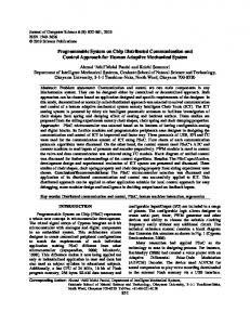
The cs2 coprocessor was implemented on an Altera Apex 20K200E FPGA, as part of an application SoC as shown in Figure 8. The size of the cs2 coprocessor was measured for sample implementations consisting of 3, 4, 6, 8, 12 and 16 tasks. (Note that each implementation includes the mandatory Idle and Irq tasks). The size of the implementation can be measured in three ways: programmable logic gates,
872
Figure 8: SoC with cs2 coprocessor 60 LE ESB 50
% resource use
40
30
20
10
Figure 6: Periodic task FSM 0 2
4
6
8
10
12
14
size
(for
16
n task
Figure 9: cs2 coprocessor EP20K200E FPGA)
Altera
memory and pins. Since the cs2 coprocessor does not use pins, only gates and memory were used to compare size. The Apex 20K200E has 8320 logic elements (LE) that provide approximately 200K gates and has embedded system blocks (ESB) that provide up to 13KB of ram. The LE and ESB usage of the cs2 coprocessor is plotted against the number of tasks in Figure 9. Lines were fit by linear regression with R2 = 0.99 for LE and R2 = 0.97 for ESB. For reference, when the SoC in Figure 8 was implemented without the cs2 coprocessor, it used 33% of LEs and 24% of ESBs.
4.2
Coprocessor Performance
Two timing parameters need to be considered when part of a real-time kernel is implemented in a coprocessor. They are: 1. response time (i. e. the maximum scheduling delay), 2. processor overhead. With the cs2 kernel, in the worst case, an event that causes scheduling is first processed by the coprocessor and subsequently by the kernel. Worst-case execution time of the cs2 coprocessor (Ccs2 coproc ) and of the cs2 kernel (Ccs2 ) are combined for the response time. The processor overhead consists of the time consumed on the CPU by the kernel (Ccs2 ). Response time is analyzed first.
Figure 7: Aperiodic task FSM
873
events. Ccs2c oproc grows linearly, while 4Ckern grows logarithmically. For P = 1, which least favours the cs2 coprocessor, using the cs2 coprocessor results in faster response time for n ∈ [1, 89]. As P is increased, the value of n for which the cs2 coprocessor achieves speedup also increases. Having established that the cs2 coprocessor is beneficial to kernel response times (for finite ranges of n), the second issue of processor overhead is now addressed. Clearly, the cs2 kernel uses less CPU time than the cs1 kernel. The more important question is how 4Ckern improves application performance. To study this question, a measure called processor utilization is employed. Processor utilization, U , is defined by Liu and Layland [5] as: n X Ci (1) U= Ti i=1
Table 1: Worst-case execution times Ccs1 902 + 264I + 136dlog2 ne + 101P + 100dlog2 neP Ccs2 832 + 264I Ccs2 coproc 32 + 20n Table 1 lists worst case execution times (in cycles) for the cs1 and cs2 kernels and the cs2 coprocessor. There are several variable terms in Ccs1 : n is the number of application tasks, I is the maximum number of application coprocessor interrupts that might occur simultaneously, and P is the maximum number of periodic tasks that might be released simultaneously. n, I, and P are all application parameters. Note that Ccs2 is independent of n and P . The third entry in Table 1 is the worst-case execution time of the cs2 coprocessor. Ccs2 coproc occurs when a periodic task terminates in one cycle and then its release date occurs in the next cycle. Consider again the Periodic Task FSM in Figure 6. Suppose that a task is in the alive state and has just had its time-slice in the rotation. It will not be processed again until the next rotation. If the terminate signal arrives just after its slice, it will take one full rotation before it transitions to the dead state. It will take an additional three rotations to transition through the fetal state, natal state and into the alive state. Once in the alive state, if this task is the first time-slice in the rotation (after the Idle task), then the Irq task will not schedule it (raise the irq) until the other n − 1 tasks have bid on the earliest deadline. Each rotation takes n + 2 time-slices for the n application tasks and the Idle and Irq task. It can therefore take up to nslice
where Ci is the worst-case execution time of task i, and Ti is the period for periodic task i, or the minimum interarrival time for aperiodic task i. U sums the fraction of processor time required by each task. For a set of tasks to be feasibly scheduled by EDF policy, processor utilization must not exceed 100% (U ≤ 1). Note that the kernel is invoked at each each task release and finish so 2Ckern is added to each task execution time Ci when performing the analysis. This ignores any extra kernel invocations due to task blocks or unblocks. The impact of kernel speedup on processor utilization is therefore: 4U =
= 4(n + 2) + n = 8 + 5n
= 4 ∗ nslice = 32 + 20n.
5.
For example, consider an application with 8 tasks and 1 application coprocessor. If at most 3 of the periodic tasks will be released simultaneously, then the parameters are:
BENEFIT/COST RATIO
To integrate a kernel coprocessor into the hardware/software partitioning of SoCs, a metric is needed to compare benefits of the kernel coprocessor with other application coprocessor candidates. To facilitate this comparison, a benefit/cost ratio is suggested here. The benefit is the decrease is processor utilization, 4U , and the cost is the implementation size of the coprocessor. If the SoC is being implemented on an Apex FPGA, then two such ratios are possible:
n = 8, I = 1, P = 3. Assuming that the system clock runs at 33 MHz, then the worst-case execution times are: Ccs1 Ccs2 Ccs2 coproc
(2)
Not only does the cs2 coprocessor decrease kernel execution time, the number of kernel invocations may also be decreased. In the cs1 kernel, the kernel must be invoked to perform scheduling whenever a task’s status changes. If, as a result of the scheduling, a different task must run, then a context switch is also performed. In the cs2 kernel, scheduling activity is performed by the cs2 coprocessor and so the software kernel need only be invoked when a context switch is performed.
time-slices from the arrival of the terminate signal to the raising of the irq. In the current application, the cs2 coprocessor is clocked at half the system frequency. In addition, each time-slice takes 2 clock ticks. Therefore the maximum delay (in system cycles) is ncycle
n X 24Ckern . Ti i=1
84µs 33µs 5.8µs
4U LE
In this example the response time of cs2 (5.8 + 33 = 38µs) is faster than that of cs1. Also the cs2 kernel processor overhead is less than the cs1 kernel processor overhead. The difference in worst-case execution time between the cs1 kernel and cs2 kernel, 4Ckern , is
4U ESB
Since both LE and ESB resources are limited to 100% usage, it is suggested that the resource closest to 100% be considered the critical value for a given candidate. A test case was implemented that consisted of an idle engine model, controller and simulated environmental input as described in [7]. It consisted of 6 application tasks, one of which simulated environmental input. This task executed frequently and much of its time was consumed in calculating angle cosines in software. A coprocessor was developed
70 + 136dlog2 ne + 101P + 100dlog2 neP. As long as 4Ckern > Ccs2 coproc , then using the cs2 coprocessor improves worst-case response time to scheduling
874
Coprocessor cosine cs2
Table 2: Coprocessor comparison 4t 4U LE 4U/LE 4tenv = 1.337µs 4U = 0.2164 46% 0.4704 4tkern = 0.06138µs 4U = 0.1270 30% 0.4235
to implement the cosine function in hardware. Table 2 compares the results of using the cosine coprocessor verses the cs2 coprocessor to speed up this application. Note that theoretical worst-case times for the cosine software were not available, so measured worst-case times were used in this comparison. The data was obtained from an Apex 20K200E FPGA with an embedded 32-bit Nios CPU running at 33 MHz. The cosine coprocessor decreased worst-case execution time of the environment task (4tenv ) by much more than the cs2 coprocessor decreased the worst-case execution time of the kernel (4tkern ). However since the kernel is invoked more often, the difference in processor utilization (4U ) is not as great. In both the cosine and cs2 coprocessor, more logic elements are consumed than embedded systems blocks, so 4U/LE becomes the metric for comparison. In this case the cosine coprocessor has a slightly higher benefit. However, the cosine coprocessor consumes almost half of the target FPGA’s area which might preclude it’s consideration if the target FPGA is a smaller device. It is also important to note that the cs2 coprocessor can be easily applied to any application that runs under the cs1/cs2 kernels by configuring the task parameters and compiling the coprocessor.
6.
[4]
[5]
[6]
[8]
[9]
ACKNOWLEDGMENTS
This work supported in part by NSERC (Natural Sciences and Engineering Research Council of Canada).
8.
[3]
[7]
CONCLUSION
The design and analysis has been presented for a kernel coprocessor that implements the Earliest Deadline First scheduling policy. The coprocessor grows linearly in size with the number of tasks. It improves the response time of the kernel and reduces the kernel processor overhead. A benefit/cost metric has been introduced to facilitate unified evaluation of kernel and application coprocessors for an SoC. The metric was demonstrated with the idle engine application. Although the cosine coprocessor had a slightly higher benefit/cost ratio, the cs2 coprocessor had the advantage of being easily customized to a broad range of applications. It is interesting to note from Figure 9 that when the cs2 coprocessor is configured for 9 tasks, it is close in size to the CPU (∼ 33% logic elements). This leads to the question of whether it is better to add a cs2 coprocessor or an additional CPU to a design. The answer is not obvious since an additional CPU would require a multi-processor kernel, incurring a higher kernel overhead. The answer would depend in part on the granularity and number of tasks, and their interdependencies. Answering this question involves modeling multi-processor kernel overhead and it’s impact on application feasibility. This is a subject for further investigation.
7.
[2]
REFERENCES
[1] J. Adomat, J. Furun¨ as, L. Lindh, and J. St¨ arner. Real-time kernel in hardware rtu: A step towards
875
ESB 25% 2%
4U/ESB 0.8656 6.353
deterministic and high-performance real-time systems. In Proceedings of the Eighth Euromicro Workshop on Real-Time Systems, pages 164–168, 1996. J. R. Jackson. Scheduling a production line to minimize maximum tardiness. Research Report 43, Management Science Research Project, University of California, Los Angeles, 1955. J. Lee, V. J. Mooney III, A. Daleby, K. Ingstr¨ om, T. Klevin, and L. Lindh. A comparison of the rtu hardware rtos with a hardware/software rtos. In Proceedings of the Asia and South Pacific Design Automation Conference, pages 683–688, January 2003. L. Lindh and F. Stanischewski. Fastchart-idea and implementation [virtual machine]. In Proceedings IEEE International Conference on Computer Design: VLSI in Computers and Processors, pages 401–404, 1991. C. L. Liu and J. W. Layland. Scheduling algorithms for multiprogramming in a hard-real-time environment. Journal of the ACM, 20(1):46–61, January 1973. V. J. Mooney III and D. M. Blough. A hardware-software real-time operating system framework for socs. IEEE Design & Test of Computers, 2002. A. Morton and W. M. Loucks. Real-time kernel support for coprocessors: Empirical study of an sopc. In Proceedings of the Embedded Systems and Applications Conference, pages 10–14, 2003. T. Nakano, A. Utama, M. Itabashi, A. Shiomi, and M. Imai. Hardware implemenation of a real-time operating system. In Proceedings of the 12th TRON Project International Symposium, pages 34–42, 1995. RealFast. Ultrafast micro kernel (ufµk) - hw os accelerator. World wide web document, http://www.realfast.se/rfipp/products/s16/UFK datasheet.pdf, 2002.