model of product development costs for modular products. In the next sections, ..... wide range of consumer applications, customer needs, and overall functions.
A HEURISTIC METHOD TO IDENTIFY MODULES FROM A FUNCTIONAL DESCRIPTION OF A PRODUCT1 Robert B. Stone Department of Basic Engineering University of Missouri-Rolla Rolla, MO
Kristin L. Wood and Richard H. Crawford Department of Mechanical Engineering The University of Texas at Austin Austin, TX 78712
Abstract Developing product architectures is a key phase in design and development processes. It encompasses the transformation of product function to alternative product layouts. In this paper, we describe a new approach for identifying modules for product architectures. We begin by reviewing the terminology and motivation for modular products. Following that discussion, three heuristic methods of identifying modules from a formal functional decomposition are presented. To aid in this process, a concept known as functional dependency is introduced to further arrange functional models with respect to time. Through this concept and heuristic methods, modular design can be executed earlier in the product development process, as illustrated by the running example of a power-tool product. A database of 70 consumer products is used to verify and confirm the overall modular design approach.
1 INTRODUCTION Modules are defined as physical structures that have a one-to-one correspondence with functional structures (Ulrich and Tung, 1991). Modular products may be defined as machines, assemblies or components that accomplish an overall function through combination of distinct building blocks or modules (Pahl and Beitz, 1988). While modular products have distinct manufacturing advantages in many instances, modularity in mechanical design is often an afterthought.
Once a product is designed and developed, components of the product are
observed to have other potential uses. This can lead to faster development and reduced costs in future product designs.
However, if modularity is identified and exploited in the initial
conceptual or reverse engineering1 effort, the immediate product design reaps benefits in reduced development time and costs (Congress, 1992; Pahl and Beitz, 1988). ASME DETC DTM Conference, 1998. Reverse engineering initiates the redesign process, wherein a device is predicted, observed, disassembled, analyzed, tested, “experienced,” and documented in terms of its functionality, form, physical principles, manufacturability and assemblability (Otto and Wood, 1996). 1 1
1
Combining components has been addressed in recent work on automated design techniques (Bradley and Agogino, 1994; Ward, 1989; Ward and Seering, 1993; Schmidt and Cagan, 1997a & b; Vadde et al., 1992). Likewise, significant advancements have been made in integrating components or reducing part count at the form-level of design (Gupta and Krishnan, 1997; Boothroyd and Dewhurst, 1989; Marks, et al., 1993; Newcomb, et al., 1996; Pimmler and Eppinger, 1994; Rosen, 1996; Poli, et al., 1986; Dixon and Poli, 1995). However, how do we define what the function of a module is? How do we define appropriate module interfaces and opportunities? Both Cutherell (1997) and Ulrich and Eppinger (1995) present a four step process for defining a module-based product architecture. This process begins by decomposing a product into functional schematics, then defining “chunks” as possible modules. Yet, it lacks a systematic technique for clustering elements and defining interactions.. The heuristic methods in this paper provide such a technique.
Once modules are defined,
alternative layouts and component selection are more straightforward tasks.
Economic
tradeoffs may then be applied to the alternatives, using, for example, Krishnan et al.’s (1996) model of product development costs for modular products. In the next sections, we present a technique that arranges a functional model of a product into the proper form for identification of modules. This technique relies on the concept of “function dependencies.” 2 FUNCTION DEPENDENCIES In functional models, known as function structures, flow refers to the energy, material or signal that travels through the sub-functions of a device. Decomposition techniques, like Pahl & Beitz (1988), trace flows through sub-functions without regard for the dependence of subfunctions on a specific order. Ulrich & Eppinger (1995), though, note that task dependencies for product development processes are either parallel, sequential or coupled, where the tasks are analogous to sub-functions and the time and information resulting from each task are analogous to flows. Here we extend the concept of parallel and sequential dependencies to sub-
2
functions and flows of a function structure. In each case, the dependencies are defined with respect to a given flow. The benefit of classifying and ultimately arranging a function structure based on the dependencies of its flows and functions will become evident when the module identification method is presented in the next section. For now, suffice it to say that for any design problem, regardless of the concern for modules, any additional information that can be contained in the function structure will expedite decisions in the conceptual phase. 2.1 Sequential Function Chains In sequential function chains, the sub-functions must be performed in a specific order to generate the desired result. A flow common to all these functions is termed a sequential flow. This concept is directly analogous to a series circuit. In Fig. 1 (a), the resistors R1 and R2 and capacitor C1 are analogous to sub-functions of a device. The current, i, is the flow common to all sub-functions. Because of the physical layout of the circuit, the flow (current i) must “travel” through each sub-function in a specific order (first R1, next C1 and finally R2). R1
R1
i1 +
i2
+
Vs
C1
i -
Vs
C1
i
R2
-
R2 (a)
Figure 1
(b)
Electrical circuit analogy with sequential and parallel sub-function chains. (a) Series circuit and (b) parallel circuit.
2.2 Parallel Function Chains Parallel function chains consist of sets of sequential function chains sharing one or more common flows. Graphically, they are represented by branching flows in a function structure. 3
The chains are called parallel because they all depend on a common sub-function and flow, but are independent of each other. Independence means that any one of the chains of the parallel function chain set does not require input from any other chain within the set. Physically, the parallel function chains represent different components of a device that may operate all at once or individually. The circuit in Fig. 1 (b) is analogous to the parallel function chains introduced here. As before, the resistors and capacitor act as sub-functions, but the voltage is the “flow.” Sub-functions C1 and R2 are in parallel and thus experience the same flow of voltage potential. Both sub-functions C1 and R2 depend on the flow out of R1, but do not depend on each other. Switches are included in the sequential legs of the parallel chain to indicate that either one or both of the sequential legs may operate at the same time. This is exactly the situation described by the parallel function chains above. 3 THE METHOD OF MODULE HEURISTICS Using the concept of function dependencies, we now move on to the method by which modules can be identified at a functional level. The method of module heuristics consists of three separate strategies to identify modules. The necessary starting point is a well refined function structure. We refer the reader to recent work on functional decomposition by Little et al., (1997), McAdams et al. (1997), and Stone (1997) for more information. In these works, function structures are formalized using a common basis of functions and flows. Conceptualized function structures for products may be transformed into a common form using these basis functions and flows. Through this process, functions may be directly related to customer needs, products and their functional representations may be directly compared, product families may be identified, product functions may be prioritized, and direct component analogies may be generated within and outside product classes. Assuming the existence of a refined function structure, consider our approach to heuristic module identification.
Webster’s dictionary defines a heuristic as “a method of
education or of computer programming in which the pupil or machine proceeds along empirical lines, using rules of thumb, to find solutions or answers.” Here is our working 4
definition of module heuristics: A method of examination in which the designer uses a set of steps, empirical in nature, yet proven scientifically valid, to identify modules in a design problem. This definition requires another. “Proven scientifically valid” refers to a hypothesis, formulated after systematic, objective data collection, that has successfully passed its empirical tests. This is based on the scientific method. We introduce three heuristic methods below as developed from these definitions. These methods offer surprisingly simple definitions of modules from transformed function structures. However, each of the methods may identify overlapping modules or modules which are subsets or supersets of other modules. The choice of which module to implement in that case is not always clear. The rule suggested here is to implement the module with the smaller number of sub-functions. This idea is in keeping with the philosophy that modules should be easily identifiable with a particular function.
Ultimately, though, which module to implement
requires some engineering judgment. As the three heuristics are introduced, a function structure of a SKIL Twist power screwdriver, is used as a physical example. The power screwdriver was chosen for the example series because it deals with several material flows. Some of the modules identified by the heuristics appear as modules in the current product and others offer areas for future modularity. The function structures were generated by the reverse engineering method of Otto and Wood (1996). We will show the identified modules in the power screwdriver for each heuristic, discuss which ones exist and which ones present opportunities for a more modular design. 3.1 Dominant Flow The dominant flow heuristic examines each flow of a function structure and groups the sub-functions the flow travels through until it exits the system or is transformed into another flow. The identified set of sub-functions define a module that deals with the flow traced through the system.
The identified sub-functions form the boundary, or interface, of the
module. Any other flows, in addition to the traced flow, that cross the boundary are interactions 5
between the module and the remaining product.
A dominant flow module is shown
schematically in Fig. 2. To implement the module, conduits must be specified to carry the interactions across the interface. Stated succinctly, the dominant flow proposition is: Proposition 1: The set of sub-functions which a flow passes through, from entry or initiation of the flow in the system to exit from the system or conversion of the flow within the system, define a module. dominant flow module material
energy
interaction interface
Figure 2
Dominant flow heuristic applied to a generic function structure.
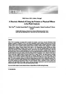
Screwdriver - Identified modules In the SKIL Twist power screwdriver, the highest ranked (from customer needs), nonbranching flow is that of electricity. Electricity passes through four sub-functions as outlined by a dashed rectangle and shown in Fig. 3. supply electricity, actuate electricity and regulate electricity all have the flow electricity. The dominant flow heuristic identifies that these sub-functions could be combined as one module, here we’ll name it the electrical supply module. The next flow to trace is the bit. It first enters the system and traces through the two sub-functions couple solid and secure solid. This set of sub-functions forms a module that we’ll call the coupling module. The flow torque emerges from the convert electricity to torque subfunction and travels through the sub-functions change torque, transmit torque, rotate solid and dissipate torque. Here the heuristic identifies four sub-functions that form the torque transmission module. 6
bit hand
couple solid
human force
import hand
hum. coupling module hum. force force hand hand secure bit solid bit
hand
secure rotation
hum. force
hand separate solid
human force
hand
dissipate torque
hand
allow rot. DOF
heat, vibration human force
hand
hand
import hum. force
regulate rotation
hum. force
regulate translation
rot. & trans. ener. heat
human force
supply electricity module electricity
store electricity
supply electricity
human force
torque
elect.
actuate electricity
elect.
regulate electricity
convert elec. to torque
elect.
bit
torque
torque transmission module change torque
torque
transmit torque
h.f. torque bit
rotate solid
h.f. torque bit
dissipate torque
hum. force, heat, noise, vibration bit
Material flow Energy flow Identified modules
Figure 3
Modules identified by the dominant flow heuristic from a function structure of the SKIL Twist power screwdriver.
For the power screwdriver, the dominant flow heuristic identifies three modules, one for each purely sequential function chain. Not all product function structures will have a module associated with every non-branching flow. In some instances, flows may enter only one subfunction and then exit the system or be transformed, thus never forming a sequential function chain. Next, we discuss how the identified modules compare with existing modules and how others offer an opportunity for a improved modular design.
7
(a) Overview (b) Exploded view
(c) Switch
(e) Transmission and rotational lock
(d) Motor
(f) Rechargeable battery
Figure 4
Views of the SKIL Twist power screwdriver.
Screwdriver - Actual modules The identified modules are now verified by checking the actual product.
Actual
modules will be referenced with respect to the exploded view shown in Fig. 4. The module associated with the flow of electricity is actually found as two modules in the SKIL Twist power 8
screwdriver.
The store electricity and supply electricity sub-functions are embodied by a
rechargeable battery, while the actuate electricity and regulate electricity functions form a switch module (to turn on as well as change the direction of the screwdriver). These two sub-modules are shown in Fig. 4 (c) and (f). In this sense, the heuristic method correctly identifies subfunctions that come together as a module. A possible product improvement, shown in Fig. 5, integrates the four sub-functions into a single component that stores, supplies and actuates electricity and interfaces with other drive units besides screwdrivers. The rechargeable battery solves the store electricity sub-function. The switch handles the sub-functions actuate electricity and regulate electricity. The contacts supply electricity for associated drive units. With this concept, the supply electricity module, would interface with different drive modules to create a mix modularity tool. For example, it could attach to a screwdriver, drill, detail sander or flashlight drive unit.
This approach advances the modular battery powered hand tools
available today a step further. Predicted modules associated with the flows bit and torque exist in the screwdriver as well. The coupling module and a subset of the torque transmission module (sans the change torque sub-function) are embodied by the same physical component (Fig. 4 (e)).
Note that the
dominant flow method does not identify this module sharing opportunity, i.e. the possibility of a single, physical module to embody two or more module concepts. Thus, the dominant flow heuristic method predicts modules that exist in the screwdriver.
In addition, it provides an innovative way of combining functions into one
component that could be shared among products. Another point to note about the dominant flow heuristic is that it defines functions that can be combined into assembly modules, i.e. parts that are best connected together before assembling the entire product. 3.2 Branching Flows The second heuristic is referred to as “branching flows” The method of the branching flow heuristic first requires identification of flows that branch into parallel function chains. Once identified, we will examine them in descending rank order. Each branch of the flow 9
defines a potential module as shown schematically in Fig. 6. The module is formed of the subfunctions that make up the branch (each branch consists of a sequential function chain). All modules (one per branch) must interface with the product at the last sub-function before the flow branches. All flows that cross this interface are the interactions between the remaining product and the module.
Figure 5
Schematic of a possible supply electricity module for the SKIL power screwdriver. The side view is shown in (a) and the end view in (b).
Note that branching flows will identify products capable of component swapping or bus modularity. The interface boundaries defined are physical connections between module and product. In some cases they will be well-defined geometric connections, like various end mill attachments on a milling machine. Other times, the interface may be more fuzzy, like the differing interactions between the hand and the SKIL Twist power screwdriver. 10
The branching flow heuristic is stated formally as: Proposition 2: Parallel function chains associated with a flow that branches constitute modules. Each of the modules interface with the remainder of the product through the flow at the branch location.
flow branching module 1
flow branching module 2
flow branching module 3
interface
Figure 6
Flow branching heuristic applied to a generic function structure.
Screwdriver - Identified modules The power screwdriver has three flows that branch, the bit, hand and human force. Of the three flows, human force has the higher rank according to customer needs, and will be examined first. Following the sub-function import human force, the flow branches into five limbs. Each branch represents a module as shown in Fig. 7.
The five identified modules are the
coupling/decoupling, rotational lock, positioning, actuating and bit-torque transmission modules. Note that a subset of the coupling/decoupling module was identified by the dominant flow heuristic. The bit-torque transmission and actuate modules are subsets of modules identified by the dominant flow heuristic. The rotational lock and positioning modules are new. The second branching flow of the hand splits into three limbs. In this case, two of the identified modules, coupling/decoupling and positioning, are the same as identified by the flow
11
human force. The third module, named manual use, is a superset of the rotational lock module identified by the flow human force. The branching flow of bit identifies two possible modules: decoupling and bittransmission. The decoupling module, together with the coupling module of the dominant flow heuristic, constitutes the coupling/decoupling module already identified. The bit-transmission module was previously identified as well.
bit
coupling/decoupling module
hand
hum. coupling module hum. force force hand secure hand bit solid bit
import hand
couple solid
decoupling module hand separate solid
human force
human force
manual use module
rotational lock module hand hand
secure rotation
hum. force
dissipate torque
hand
allow rot. DOF
heat, vibration positioning module human force
hand rot. & trans. ener.
hand
import hum. force
regulate rotation
hum. force
regulate translation
heat
human force
actuating mod. electricity
store electricity
supply electricity
human force
torque
elect.
actuate electricity
elect.
regulate electricity
convert elec. to torque
elect.
bit
torque
bit-torque transmission module change torque
torque
transmit torque
h.f. torque bit
rotate solid
h.f. torque bit
dissipate torque
hum. force, heat, noise, vibration bit
Material flow Energy flow Identified modules
Figure 7
Modules identified by the flow branching heuristic from a function structure of the SKIL Twist power screwdriver.
Screwdriver - Actual modules The branching flow heuristic identifies several modules that overlap with the modules from the dominant flow heuristic in addition to two new modules. The coupling/decoupling and bit-torque transmission modules are embodied by the same component as the coupling and torque12
transmission modules of the previous section. The actuating module is a subset of the supply electricity module. The manual use module is embodied by a tab that locks the screwdriver transmission in place, as shown in Fig. 4 (e). Also, the positioning module is essentially the plastic casing of the screwdriver. A few remarks about the heuristics usage thus far are warranted. It is evident that they identify overlapping modules in some cases. At this point, we wonder about which module to implement in such a case. Section 4 of this paper summarizes a customer needs approach to determining which module to implement. For now, we make the observation that the more ways a module is identified (in terms of heuristics and flows), the more important it is to implement (since it must be associated with more customer needs). 3.3 Conversion-Transmission Modules The third heuristic method deals with conversion sub-functions and conversion to transmission chains. Conversion sub-functions accept a flow of material or energy and convert the flow to another form of material or energy. In many cases, these conversion sub-functions are already components or modules themselves.
For instance, electrical motors, hydraulic
cylinders, and electrical heaters can all be represented by a single conversion sub-function and exist physically as a single component. If, additionally, a conversion sub-function exists in a chain with a transmit sub-function (or transport sub-function for material flow), then the chain presents an opportunity to form a module which converts an energy or material to another form and then implements (transmits or transports) that new form of energy or material. The method of the conversion-transmission heuristic, shown schematically in Fig. 8, is simple. The essential actions are as follows: identify conversion sub-functions and check for transmit or transport sub-functions downstream of the converted flow. If none exist, then the conversion sub-function is a module by itself. If transmit or transport sub-functions exist without any other sub-functions between them, then the convert-transmit (transport) pair represents a module. If other sub-functions exist between the convert and transmit (transport) sub-functions and those intermediate sub-functions only operate on the converted flow (i.e. the 13
object in the sub-function verb-object pair is the converted flow), then the conversiontransmission (transportation) chain represents a module. conversion mod. convert flow A to flow B conversion-transmission pair convert flow A to flow B
convert flow A to flow B
Figure 8
transmit (transport) flow B conversion-transmission chain transmit function (transport) flow B flow B
Conversion-transmission applied to a generic set of sub-functions.
Interfaces of a conversion-transmission module are defined in a similar manner as those for a dominant flow module. Two necessary interactions across the interface are the flow to be converted and then the exiting converted flow. Additional flows may also cross the interface. The conversion-transmission proposition, stated succinctly, is: Proposition 3: A conversion sub-function or a conversion-transmission pair or proper chain of sub-functions constitutes a module. Screwdriver - Identified modules Consider the power screwdriver again, the conversion-transmission heuristic identifies one module as shown in Fig. 9. It consists of three sub-functions, the bounding convert electricity to torque and transmit torque and the intermediate sub-function change torque. The interface of the electricity to torque module is outlined in Fig. 9. The interactions are the two necessary flows of electricity and torque along with heat and coupled bit.
14
bit hand
couple solid
human force
import hand
hum. force hand bit
secure solid
hand
secure rotation
hum. force
hum. force hand bit
hand separate solid
human force
hand
dissipate torque
hand
allow rot. DOF
heat, vibration human force
hand
hand
import hum. force
regulate rotation
hum. force
regulate translation
rot. & trans. ener. heat
human force
electricity
store electricity
supply electricity
human force
torque
elect.
actuate electricity
elect.
regulate electricity
convert elec. to torque
elect.
bit
torque
electricity to torque module change torque
torque
transmit torque
h.f. torque bit
rotate solid
h.f. torque bit
dissipate torque
hum. force, heat, noise, vibration bit
Material flow Energy flow Identified modules
Figure 9
Module identified by the conversion-transmission heuristic from a function structure of the SKIL Twist power screwdriver.
Screwdriver - Actual modules In the actual product, the three sub-functions are not embodied as a single module. The convert electricity to torque sub-function is a distinct component, shown in Fig. 4 (d). The change torque and transmit torque sub-functions, though, are part of the torque transmission module in Fig. 4 (e). In this case, the method provides an innovative approach to the design of a module that incorporates a motor, transmission, and drive-train. Recall the innovative supply electricity module of the screwdriver in Figure 5. In concert with the supply electricity module, the electricity to torque module becomes the drive units in a mix and match set of power packs with switches and motor drive units.
15
4 VERIFICATION OF HEURISTIC METHODS The three heuristic methods introduced in Section 3 are presented with the SKIL power screwdriver example. The heuristics were developed and verified more rigorously using a database of 70 products, of which the power screwdriver is a part. The products represent a wide range of consumer applications, customer needs, and overall functions. The mechanical or electromechanical products include small construction tools, small kitchen appliances, automobile accessories, small household appliances, and toys. This set of products represents over 100 person years of work in reverse engineering and redesign and is the same set used in recent papers by Little et al. (1997) and McAdams et al. (1997). The redesigns and case studies are the result of course work, research, and industrial interaction at The University of Texas at Austin. Of the 70 products, 18 are examined in detail. The 18 products are representative of the wide range of consumer applications in the entire database. Two types of products, an iced tea brewer and a power screwdriver, are repeated (same type of product, different manufacturer) to examine the differences in competing products. All product function structures produce modules when the three heuristic methods are applied. Table 1 presents the results. The products are listed in column one followed by three columns that indicate the number of modules identified by each of the three heuristic methods: dominant flow, branching flow and conversion-transmission. The next three columns indicate the actual modules found in the products, associated with the three heuristic methods. Since it is possible for the different heuristic methods to identify overlapping modules, the final two columns give the number of unique modules possible and then the actual number of modules found in the product. It is important to note from the final two columns of Table 1 that the number of unique modules possible is always greater than (or equal to for three of the products) the actual number of modules implemented in current products. This strongly supports the heuristic methods’ validity as a tool to identify possible modules in a product. For this database of consumer, largely hand-held products, four to nine unique modules are possible. The actual 16
products, though, incorporate between two to seven modules, with some exhibiting an impressive degree of modularity. As a comparison, a large heavy-duty maintenance product – a lignite removal system for the power generation industry - was examined (Stone, 1997). It has a unique module possible count of 14 for its two subsystems studied, supporting the heuristics utility for larger scale design problems. For consumer products with 15 to 30 sub-functions, we now know that, on average, six unique modules are possible. Table 1
Statistical comparison of identified modules and actual modules in 18 products. Identified modules
Actual modules
Unique
Actual
Dom. flow
Branch. flow
Conv.Trans.
Dom. flow
Branch. flow
Conv.Trans.
modul e poss.
modul e total
Mr. Coffee iced tea/coffee brewer
6
4
1
5
3
1
7
6
West Bend iced tea/coffee brewer
6
4
1
4
3
1
7
5
Product
Mr. Coffee coffee maker
5
3
1
3
1
1
6
3
B&D screwdriver
3
6
1
2
3
0
6
4
SKIL screwdriver
3
6
1
3
4
0
6
5
DeWalt sander
4
4
3
4
3
3
9
7
Bissel hand vacuum
5
3
2
4
2
2
6
6
Pencil sharpener
3
2
1
3
2
1
4
4
B&D electric knife
3
4
2
2
2
2
6
4
Presto air popcorn popper
3
2
3
3
2
3
8
6
Krups cafe trio
3
2
1
3
1
1
6
5
B&D sander
5
2
3
3
2
3
7
6
Dazey fruit/veggie peeler
5
3
2
3
2
2
7
4
Dremel engraver
3
4
1
2
2
1
5
3
1974 Chevy tailgate
3
6
1
2
3
1
5
3
B&D VersaPak trimmer
4
2
1
4
2
1
5
5
Cadillac visor
2
0
2
2
0
2
4
2
Super Maxx ball shooter
3
2
2
3
0
2
6
3
4
3
2
3
2
2
6
4
Average
In addition to the 70-product database used for verification, the module heuristics can be used to redesign products.
Let’s consider a Mr. Coffee iced tea brewer as an example
application. Following a modular design methodology by Stone (1997), the iced tea brewer is redesigned to meet two important customer needs: take less space on the counter and prevent leaking between the tea brewer base and pitcher. Figure 10 (a) illustrates an evolved product 17
architecture for satisfying these needs.
After developing this architecture, the proposed
modular redesign of the iced tea brewer turned up on store shelves. The original and evolved Mr. Coffee iced tea brewers are shown in Fig. 10 (b). This independent event provides further verification that the module heuristics are capturing an important industrial design process.
9 in. water
liquid containment water
electrical conversion
thermal energy electricity
electrical supply
filter, tea containment tea
thermal energy
thermal energy
ice
ice/tea containment
tea thermal energy
18 in.
(a)
Figure 10
(b)
Comparison of two Mr. Coffee Iced Tea Brewers. The model on the left of Fig. (b) is the older, side-by-side version. The model on the right is very similar to the proposed modular redesign shown in (a).
5 COMPLEMENTARY QUANTITATIVE METHOD So far we have used function structures and three heuristic methods to identify subfunctions that can be grouped together as a module. But how do we measure the value of modular design methodology versus integral or non-modular methodologies? There is no better measure than that of customer needs. Meeting customer needs is already a primary component of decomposition based design methodologies (Pahl & Beitz, 1988; Ulrich and Eppinger, 1995; Ullman, 1997; Otto and Wood, 1996).
Thus, the customer need ranking
becomes our metric to evaluate the utility of a module. The quantitative module assessment method, summarized in Table 2, relates customer needs to sub-function groupings that constitute modules. This procedure originated with Little et al. (1997) as a means of exploring device and function relationships by producing a device18
function matrix of normalized customer needs. It was later extended by McAdams et al. (1997) to include identification of functional relationships through a function-function matrix. This method was noted to present clear applications for module identification. Stone (1997) modifies the method specifically for module identification and it is summarized below. The quantitative method is viewed as having three steps that follow the order given in Table 2. The first step produces a normalized device-function matrix that allows a comparison of sub-functions shared by a wide domain of devices. Using the normalized device-function matrix, N, step two produces the device similarity matrix.
This matrix identifies product
families, products that have similar functions and customer needs. Step three requires the output of both steps one and two. It produces the function-function matrix, S, which calculates a customer need rating of grouped sub-functions.
These groupings of sub-functions are
potential modules. Their customer importance rating provides a metric for evaluation of the heuristically identified modules. WE AT LEAST ONE EXAMPLE RESULT HERE. Table 2
Summary of quantitative module assessment method. Step
Input
Output
Uses
1
1. List of rated customer needs 2. Function structure in functional basis
Normalized devicefunction matrix, N
Places a wide domain of devices on equal footing in terms of customer need ratings and device complexity. Allows comparison of functions shared by variety of devices.
2
1. Normalized device-function matrix 2. Generating device for family
1. Device similarity matrix,
1. Normalized device-function matrix 2. Device family of interest
1. Functionfunction matrix, S 2. Customer need rating of subfunction groups (modules)
3
2. Device family ranked with respect to the generating device
19
Identifies device families which share common sub-functions and the possibility for shared modules.
Gives function to function relationship across entire device domain based on customer needs. Within device families, it identifies the sub-functions which may be grouped as modules while satisfying customer need. The method is applicable to the entire device domain, but focusing on device families sharpens the distinctions between modules.
6 CONCLUSION This paper introduces the three heuristic methods of dominant flow, branching flow and conversion-transmission functions. These three methods provide a systematic approach to identifying modules of a product from a functional model. While their application is elegantly simple, their utility is immense. The methods were verified using a 70-product database of consumer products.
The methods always identified modules that currently exist in the
products and, more importantly, identified opportunities for increased product modularity. The heuristic method presented here, along with the quantitative method that was summarized, is part of a new tack on design methodologies. It shifts the focus to modular concept variants where solutions are sought at a modular level rather than a functional level. A natural extension of this work is the formation of development teams based on identified modules (Stone, 1997). ACKNOWLEDGMENTS
The research reported in this paper was partially supported by an Engineering Doctoral Fellowship through the College of Engineering and by a Continuing Fellowship, both awarded by The University of Texas at Austin. In addition, this work is supported, in part, by the National Science Foundation under both an NSF Young Investigator Award, Ford Motor Company, Desktop Manufacturing Corporation, Texas Instruments, W.M. Keck Foundation, and the June and Gene Gillis Endowed Faculty Fellow in Manufacturing. Any opinions or findings of this work is the responsibility of the authors, and does not necessarily reflect the views of the sponsors or collaborators.
REFERENCES Boothroyd, G. and Dewhurst, P., Product Design for Assembly, McGraw-Hill, Inc., New York, 1989. Bradley, S. and Agogino, A., 1994, “An Intelligent Real Time Design Methodology for Component Selection: An Approach to Managing Uncertainty,” Journal of Mechanical Design, 116:980-988. Congress, 1992, “Green Products by Design: Choices for a Cleaner Environment,” Office of Technology Assessment, OTA-E-541, Washington, D.C.
20
Cutherell, D., 1996, “Chapter 16: Product Architecture,” The PDMA Handbook of New Product Development, M. Rosenau Jr., et al., ed., John Wiley and Sons. Dixon, J. R. and Poli, C, Engineering Design and Design for Manufacturing, Field Stone Publishers, Conway, MA, 1995. Krishnan, V., Singh, R., and Tirupati, D., 1996, “A Model-Based Approach for Planning and Developing a Family of Technology-Based Products,” Department of Management Working Paper, The University of Texas at Austin. Little, A., 1997, A Reverse Engineering Toolbox for Functional Product Measurement, Master Thesis, The University of Texas at Austin. Little, A., Wood, K., and McAdams, D., 1997, “Functional Analysis: A Fundamental Empirical Study for Reverse Engineering, Benchmarking and Redesign,” Proceedings of the 1997 Design Engineering Technical Conferences, 97-DETC/DTM-3879, Sacramento, CA. McAdams, D., Stone, R., and Wood, K., 1997, “Functional Interdependence and Product Similarity Based on Customer Needs,” Submitted for review to Research in Engineering Design. Otto, K. and Wood, K., 1996, “A Reverse Engineering and Redesign Methodology for Product Evolution,” Proceedings of the 1996 ASME Design Theory and Methodology Conference, 96DETC/DTM-1523, Irvine, CA. Pahl, G. and Beitz, W., 1988, Engineering Design: A Systematic Approach, Springer-Verlag. Poli, C. et al., “Rating Products for Ease of Assembly,” Machine Design, August, 1986. Schmidt, L. and Cagan, J., accepted 1997a, “Optimal Configuration Design: An Integrated Approach Using Grammars,” To appear in Journal of Mechanical Design. Schmidt, L. and Cagan, J., accepted 1997b, “GGREADA: A Graph Grammar-Based Machine Design Algorithm,” To appear in Research in Engineering Design. Ullman, D., 1997, The Mechanical Design Process 2nd ed., McGraw-Hill. Ulrich, K. and Eppinger, S., 1995, Product Design and Development, McGraw-Hill. Ulrich, K. and Tung, K., 1991, “Fundamentals of Product Modularity,” Proceedings of the 1991 Winter Annual Meeting, DE-Vol. 39, Atlanta, GA. Ward, A., 1989, A Theory of Quantitative Inference Applied to a Mechanical Design Compiler, Doctoral Thesis, Massachusetts Institute of Technology. Ward, A. and Seering, W., 1993, “Quantitative Inference in a Mechanical Design ‘Compiler’,” Journal of Mechanical Design, 115:29-35.
21