2Department of Computer Science and Information Engineering, Formosa University, Hu-Wei, Taiwan 632-08. Abstract ... architectures of LCD and TV signal processor. But the industry of LCD ... In this scalar, we may not use the special purpose ... The new horizontal line (row) is created by four-upper ..... Company, 2000.
A High-Efficient and Cost-Effective LCD Signal Processor Tze-Yun Sung1 Chun-Wang Yu1 Yaw-Shih Shieh1 Hsi-Chin Hsin2 1
2
Department of Microelectronics Engineering, Chung Hua University, Hsinchu, Taiwan 300-12, R.O.C. Department of Computer Science and Information Engineering, Formosa University, Hu-Wei, Taiwan 632-08
Abstract This paper investigates the system of LCD monitor and TV signal processor. It is shown that the processor provides scalar, brightness and contrast adjuster, Gamma correction and dithering. The algorithms are discussed and implemented by Verilog hardware description language. The key hard codes are displayed. The signal processor for monitor and TV achieves real-time and high performance. The system is evaluated and implemented on FPGA (XilinxXC2V6000). Keywords: LCD, scalar, brightness and contrast adjuster, Gamma correction, dithering.
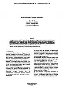
1. Introduction In this paper, we discuss the algorithms of image scalar, brightness, contrast adjuster, Gamma correction and dithering. The system is integrated and the performance of the signal processor achieves real-time, area and power consumption under FPGA implementation are also optimized [1], [2]. The system diagram of control circuits of LCD monitor and TV is shown in Figure 1, the system is composed of analog to digit converter, video decoder and signal processor, which includes controller and microcontroller [3]. In the initial state, the microcontroller reads data from flash memory and writes commands and tables into register file of controller [4]. So far, we rarely find papers and documents to describe and discuss the algorithms and system architectures of LCD and TV signal processor. But the industry of LCD has been growing rapidly, and has become the main stream of high technology in Taiwan. This paper present the key components of the monitor and TV signal processor and propose the algorithms and the circuits implemented by Verilog codes [2]. The remainder of this paper is organized as follows. Section II presents the image scalar algorithm, and displays the key Verilog code, which describes the circuits of the scalar algorithm. In Section III, the algorithm and implementation of the brightness and
contrast adjuster are proposed. Section IV applies the algorithm of Gamma correction to correct the input signal, and display true color. Section V presents the algorithm of dithering and implementation of the algorithm. Finally, the conclusions are given.
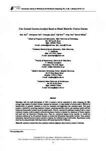
2. The Algorithm and Implementation of Image Scalar The purpose of image scalar is to enlarge and reduce the input image. The algorithm of image scalar avoids the distortion, when the scaling operation is performing. In this section, the algorithm will be described in detail. In this scalar, we may not use the special purpose digital signal processor [3]. The hardware is implemented by simple multipliers, and memory is saved. Hence, the hardware is saved, and implemented easily. Figure 3 shows the data flow of LCD monitor and TV signal processor. In Figure 2, the INP module recognizes the input signals and transfer to YUV 4:2:2 mode, which presents in video, S-video and HDTV. The SC module performs the function of image scalar. The CSC (color space converter) module transfers video signals to RGB mode. The transformation equation of CSC module is implemented by simple multipliers, adders and shifters [2], [3], [4]. In SC system, sc_fifo and sc_fifo4 module provide the memories for Y-buffer and X-buffer. All of input signal are stored in Y-buffer. The Y-buffer requires the memory capacity of 1024 (pixels) · 3-bytes · 8 (Lines), it saves hardware cost and performs the functions [4].
2.1. The Data Retrieval and Computation The new horizontal line (row) is created by four-upper and lower rows. The data are stored and computed in Y-buffer. The algorithm of new pixel creation is described as follows[3], [4]:
Pixel value= +
C3 × p_m1
C2 × p_z0 +
256 C1 × p_p1 256
+
256 C0 × p_p2 256
+ 0.5
where p_m1 ∼ p_p2 are presented as color level (0~255). According to this algorithm, the hardware is saved and the digital signal processor is not required, the low hardware cost is achieved. The key codes for performing the algorithm are described as follows: assign my_m1 = p_m1[23:16] * coeff[34:27]; // C3 assign my_z0 = p_z0[23:16] * coeff[25:18]; // C2 assign my_p1 = p_p1[23:16] * coeff[16: 9]; // C1 assign my_p2 = p_p2[23:16] * coeff[ 7: 0]; // C0 assign ry = myr + { 8'b0, myr[16:8] } + 8'h80;
When we reduce lines and get the inc_p as follows: inc_p = 1, 1, 1, 2, 1, 1, 1, 2, 1, 1…. The algorithm is described as follows: Line 20
16 17
Line 21
18
Line 22 Line 23
19
Line 24 Line 25 Line 26 Line 27
where Line 16~19 are new lines for reducing the image.
2.2. The Algorithm of Expanding and Reducing Lines
2.3. The Parameters for Expanding Pixels and Lines
In Y-buffer, we perform expand and reduce operation by using data set of horizontal scan lines to stay or jump. For example, if the data of original image is 800 horizontal lines, we may expand to 1024 lines; the special algorithm is developed and explained as follows:
In order to adjust the color and smooth the color distribution, the parameters or weighing factors must be found [3]. The data for computing the parameters are presented as follows:
inc_p = 1, 1, 1, 0, 1, 1, 1, 0, 1, 1, 1, 1, 0, 1, 1, 1, 0, 1…. Line 20 Line 21 Line 22 Line 23
Line 30
…
P20 200
Line 31
…
P20 180 P20 160
25 26 27
28 29
Line 24 Line 25 Line 26
The numbers of left side presents the sequence of the new horizontal scan lines. The line 22 (L22)~line 25 (L25)generates new line 27, the equation is represented as New line 27=a×L22 + b×L23 + c×L24 + d×25 New line 28=e×L22 + f×L23 + g×L24 + h×L25 where two set of parameters are different. The key codes for phase update are presented as follows: if (ref_d1==`BIT0 && ref==`BIT1) inc_p