Christopher Coxâ, Chunlei Liangâ and Michael W. Plesniakâ¡. Department of Mechanical & Aerospace Engineering. The George Washington University, ...
A High-Order Method for Solving Unsteady Incompressible Navier-Stokes Equations with Implicit Time Stepping on Unstructured Grids Christopher Cox∗, Chunlei Liang† and Michael W. Plesniak‡ Department of Mechanical & Aerospace Engineering The George Washington University, Washington, D.C., 20052, USA
This paper reports development of an unstructured high-order compact method for solving two-dimensional incompressible flow. This method employs the gGA correction from Huynh,1 and falls under the class of methods now referred to as Flux Reconstruction/Correction Procedure via Reconstruction.2 The artificial compressibility method3 and a dual time stepping scheme4 are used to simulate unsteady incompressible flow. A lower-upper symmetric Gauss-Seidel scheme with backward Euler discretization is used to efficiently march the solution in pseudo time, while a second order backward Euler discretization is used to march in physical time. We demonstrate order of accuracy with steady Taylor-Couette flow. We further validate the solver with steady flow past a NACA-0012 airfoil at zero angle of attack and unsteady flow past a circle. The implicit time stepping scheme is proven efficient and effective for driving the pseudo time derivative term toward zero in the classical artificial compressibility formulation. As a result, this scheme is capable of quickly establishing the divergence-free velocity condition of the continuity equation when compared to an explicit scheme.
I.
Introduction
In computational fluid dynamics (CFD), high-order unstructured methods are useful for the study of vortex dominated flows in complex geometries that are viscous and unsteady. Also, high-order methods can provide high accuracy for similar cost as low-order methods.5 Furthermore, solution acceleration can be achieved with p-refinement and p-multigrid methods. However, high-order methods are less robust and more complicated to implement, especially when dealing with irregular geometry. Four popular high-order methods used are discontinuous Galerkin (DG), spectral difference (SD), spectral volume (SV) and flux reconstruction/correction procedure via reconstruction (FR/CPR). Discontinuous Galerkin was initially developed for the neutron transport equation by Reed & Hill.6 The staggered grid spectral method was initially presented by Kopriva7 and was modified and called spectral difference by Liu et. al.8 The spectral volume method was introduced by Wang et. al.,9 where each cell is split into multiple control volumes. Flux reconstruction was initially developed by Huynh1, 10 and has a tight connection to lifting collocation penalty by Wang and Gao11 (LCP). Consequently, the involved authors coined the term Correction Procedure via Reconstruction. Further development was made on energy stable flux reconstruction schemes for triangular elements by Vincent et. al.,12 also known as Vincent-Castonguay-Jameson-Huynh (VCJH) schemes. The FR/CPR methods are a significant development because they have the ability to recover DG, SD and SV for linear problems. For a comprehensive review of these methods, see Huynh et. al.2 and Wang.13 Extensions to incompressible flows using DG for triangular and tetrahedral meshes was performed by Shahbazi et. al.14 and Nguyen et. al.15 ∗ Doctoral
Candidate, AIAA Member Professor, AIAA Associate Fellow ‡ Professor & Chairman, AIAA Fellow † Assistant
1 of 13 American Institute of Aeronautics and Astronautics
With the development of these high-order unstructured methods comes the need to achieve faster convergence, especially for solving large-scale problems. This demand motivates the development of time stepping techniques for which the CFL condition is less restrictive, which is hardly the case when explicit (e.g. multistage Runge-Kutta) schemes are combined with high-order methods. Work done to address this need can be seen in Liang, Chan and Jameson,16 whereby they use a spectral difference method to solve incompressible flow with artificial compressibility (AC) and a p-multigrid method to accelerate the convergence rate of pseudo time stepping for a particular physical time step. However, the p-multigrid method marginally improves the stiffness introduced by the artificial compressibility approach, especially for flows that require high aspect ratio cells near solid walls. As computers become equipped with larger RAM, implicit time stepping schemes are seen as effective drivers to overcome this stiffness. With these implicit schemes much larger time steps can be taken when compared to explicit schemes, delivering the potential to improve the rate of convergence significantly. In recent years, the lower-upper symmetric Gauss-Seidel (LU-SGS) scheme that was originally developed by Jameson and Yoon17 with multiple grids for solving the unsteady Euler equations has been utilized within the high-order CFD community for solving compressible flow problems on unstructured grids using spectral difference18–20 and spectral volume21 methods. When solving incompressible flows using artificial compressibility, the LU-SGS scheme is more economical because we require the solution of only three equations (in 2D) as opposed to four equations for compressible flow. Furthermore, with the introduction of artificial compressibility the pressure and velocity are coupled and the Navier-Stokes equations take on a mixed hyperbolic/parabolic mathematical nature. This modified formulation of the governing equations permits the use of flow characteristics to be specified at the boundaries. Also, artificial compressibility improves convergence issues associated with problems involving non-zero net flux into a domain with elastic boundaries, such as blood flow within a human artery. Therefore, this paper aims to bring popular high-order methods and time stepping techniques for producing high-order accurate solutions for compressible flow to the incompressible flow regime. In this regard, the current method is novel, especially if applied to moving deformable grids needed to solve problems involving fluid-structure interaction (FSI) on massively parallel computers. We first layout the governing equations with artificial compressibility and pseudo time stepping. Second, we introduce the high-order mathematical formulation. Third, we verify implementation of the method by demonstrating order of accuracy and validate solutions with test cases such as flow over a NACA-0012 airfoil and cylinder.
II. II.A.
Mathematical Formulation
Artificial Compressibility Method
The unsteady Navier-Stokes equations with artificial compressibility written in conservation form is ∂G ∂Q ∂F ∂Q + Im + + =0 ∂τ ∂t ∂x ∂y where terms involving τ and t represent pseudo and physical of conservative variables Q is p 0 Q = u , Im = 0 v 0
(1)
time derivatives, respectively, and the vector
0 1 0
0 0 1
(2)
The flux vectors F and G contain both inviscid and viscous flux terms and can be written as F = fe − fv
(3)
G = ge − gv
(4)
where
βu fe (Q) = u2 + p , uv
0
fv (Q, ∇Q) = ν ∂u ∂x ∂v ν ∂x 2 of 13
American Institute of Aeronautics and Astronautics
(5)
βv ge (Q) = uv , 2 v +p
0
gv (Q, ∇Q) = ν ∂u ∂y ∂v ν ∂y
(6)
In the above formulation, ν is the kinematic viscosity, u and v are the velocity components in x and y directions, β is the artificial compressibility relaxation parameter, and p = P/ρ, where P represents the static pressure. Unless otherwise specified, β = 1.25. II.A.1.
Mapping to Reference Element
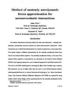
Considering the non-uniformity of the physical grid, one is motivated to transform the physical domain (x,y) into a computational domain (ξ,η) where the latter contains reference elements (0 ≤ ξ ≤ 1, 0 ≤ η ≤ 1) over which the governing equations can be efficiently solved. The transformation to the computational domain
Figure 1. 2D physical bi-linear element (left), computational reference element (right).
can be achieved through the mapping " # " # K X x x = Mi (ξ, η) i y yi i=1
(7)
where K is the number of elemental nodes per element, (xi , yi ) are the nodal cartesian coordinates, and Mi (ξ, η) are the shape functions. As shown in Fig. 1, K is 4 and node 1 is located at (ξ,η)=(0,0). After transformation into the computational domain, the governing equations for a stationary grid take on the following conservation form: ˜ ˜ ˜ ∂ F˜ ∂G ∂Q ∂Q + Im + + =0 (8) ∂τ ∂t ∂ξ ∂η where ˜ = |J|·Q Q (9) " # " # F˜ F = |J|J −1 (10) ˜ G G The Jacobian J is computed for each reference element on the stationary grid with " # xξ xη J= yξ yη
(11)
where the metrics of the Jacobian are obtained from the relationship between the non-uniform physical element and the reference element. Therefore, Eqn. (1) can be re-written as ∂Q + Rτ (Q, ∇Q) = 0 ∂τ " # ˜ ∂Q 1 ∂ F˜ ∂G Rτ (Q, ∇Q) = Im + + ∂t |J| ∂ξ ∂η 3 of 13 American Institute of Aeronautics and Astronautics
(12) (13)
where Rτ (Q, ∇Q) represents the steady state residual. The implicit LU-SGS scheme is measured against the explicit third-order, three-stage Runge-Kutta22 (RK33) scheme for its effectiveness in driving the artificial ∂p in the continuity equation closer and faster to zero in pseudo time. In both cases, time-dependent term ∂τ a second-order backward Euler scheme is used to discretize the physical time derivative. II.B.
Compact High-order Method
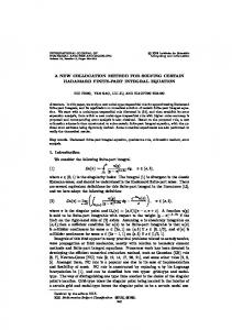
The compact high-order method presented here falls under the umbrella of FR10 /CPR.1, 11 In this type of method, the flux points are only required at element interfaces. This avoids the two-grid system and subsequent computational work associated with a staggered solution point/flux point framework. Figure 2 shows the current distribution of solution and flux points for a 3rd order method. According to Huynh,1
Figure 2. 2D distribution of solution points (SP) and flux points (FP) for 3rd order method in a reference element.
reconstruction for each cell deals with the jump in flux at each interface. Therefore, corrections need to be made to the discontinuous flux function in order to define a continuous flux function. Following the 1D formulation presented by Huynh,1 let the polynomial F˜i represent the continuous flux function in cell i that accounts for data interaction among adjacent cells by taking on common flux values at the two interfaces. The discontinuous flux function f˜i is then corrected in the following manner com LB com RB ˜ ˜ F˜i (ξ) = f˜i (ξ) + [f˜i− (ξ) + [f˜i+ (ξ) 1 − fi (0)]g 1 − fi (1)]g 2
(14)
2
This formulation provides two corrections in 1D, one correction due to the jump in flux at left boundary and the second due to the jump in flux at the right boundary of the reference element. The correction function for the left boundary must take on the values g LB (0) = 1
(15)
g LB (1) = 0
(16)
and the correction function for the right boundary must take on the values g RB (0) = 0
(17)
g RB (1) = 1
(18)
The discontinuous flux function f˜i is of degree N − 1. Both g LB and g RB are of degree N . By reflection, g RB (ξ) = g LB (1 − ξ) on the interval 0 ≤ ξ ≤ 1. Therefore, the function F˜i is of degree N and takes on the two common flux values at the interface com F˜i (0) = f˜i− (19) 1 2
com F˜i (1) = f˜i+ 1 2
4 of 13 American Institute of Aeronautics and Astronautics
(20)
This ultimately ensures flux continuity across interfaces. Once suitable correction functions for g LB and g RB have been defined for the reference element, the derivative of the continuous flux function can be computed from LB com RB com ˜ ˜ (ξ) + [f˜i+ (ξ) (21) (F˜i )ξ = (f˜i )ξ + [f˜i− 1 − fi (1)]gξ 1 − fi (0)]gξ 2
2
The derivative of the discontinuous flux term can be computed from a Lagrange polynomial or a chain-rule. In this implementation, the former method is used. Since the governing form of the incompressible equations has been modified to take on a mixed hyperbolic/parabolic nature due to the introduction of artificial compressibility, the common inviscid fluxes at the interface, f˜com , can be computed using a Riemann solver. Here, we employ the simple but robust Rusanov solver.23 The element interface normal velocity is defined as Vn = unx + vny , where nx and ny are components of the interface normal. The p three characteristics for the current 2D incompressible flow system are Vn +c, Vn and Vn −c, where c = Vn2 + β is now the pseudo speed of sound. This means that pressure waves having finite speed are introduced into the fluid, but die out as the solution approaches the divergence-free velocity condition - this is termed the pseudo steady state. The common viscous fluxes at the interface are computed using the second procedure of Bassi & Rebay,24 often referred to as the BR2 scheme. To compute these terms, the derivative of Q is needed to evaluate the derivative of the discontinuous flux function f˜. Following the formulation in Huynh1 and connecting it with the BR2 scheme, the gradient of the common solution is � 1 � RB LB (22) (Qcom i+ 12 )ξ = 2 (Qi )ξ (1) + (Qi+1 )ξ (0) where com RB QRB (ξ) (23) i (ξ) = Qi (ξ) + [Qi+ 1 − Qi (1)]g 2
QLB i+1 (ξ)
= Qi+1 (ξ) +
[Qcom i+ 12
− Qi+1 (0)]g LB (ξ)
(24)
1 [Qi (1) + Qi+1 (0)] 2
(25)
i h i o 1 1 nh com LB [(Qi )ξ (1) + (Qi+1 )ξ (0)] + Qi+ 1 − Qi (1) gξRB (1) + Qcom (0) 1 − Qi+1 (0) gξ i+ 2 2 2 2
(26)
Qcom i+ 1 = 2
Therefore, (Qcom i+ 1 )ξ = 2
Note that Eqn. (26) is compact, requiring data from cells i and i + 1 only. As a result, the computational stencil in 1D involves three elements. This compactness ultimately simplifies implementation of the boundary conditions and allows for a more economical integration of an implicit time stepping scheme. Furthermore, this stencil is friendly for implementation on massively parallel computers. II.B.1.
Correction Function
The current choice of correction function is g = gGA from Huynh1 and the solution points are the LegendreGauss points. With this choice, the jump in flux at the interface results in a correction to f˜ evaluated at all solution points. For the left boundary, the correction function is defined as LB gGA =
N N −1 RR,N + RR,N −1 2N − 1 2N − 1
(27)
where RR,N represents the right Radau polynomial RR,N =
(−1)N (PN − PN −1 ) 2
(28)
RB and PN is the Legendre polynomial. The expression for correction to the right boundary, gGA , is obtained LB simply by reflection of gGA . To construct a N −1 degree polynomial in each coordinate direction, the solution at N points is required (see Fig. 2). Within each dimension, the solution points are the Legendre-Gauss points and the flux points are the two end points 0 and 1 located along the interfaces. Choosing P−1 (ξ) = 0 and P0 (ξ) = 1, the higher-degree Legendre polynomials can be determined by
PN (ξ) =
2N − 1 N −1 (2ξ − 1)PN −1 (ξ) − PN −2 (ξ) N N 5 of 13
American Institute of Aeronautics and Astronautics
(29)
The locations of these Legendre-Gauss quadrature points are the roots of the equation PN (ξ) = 0. Using the solutions at N solution points, a N − 1 degree polynomial can be built using the Lagrange basis hi (X) =
� � N Y X − Xs Xi − Xs
(30)
s=1,s6=i
and the reconstructed solution vector in a 2D reference element is the tensor product of the two onedimensional polynomials N X N X ˜ i,j Q hi (ξ) · hj (η) (31) Q(ξ, η) = |Ji,j | j=1 i=1 II.C.
Implicit Time Stepping
In order to drive the residual closer and faster to zero for acceleration to the pseudo steady state, an implicit time stepping scheme is employed. The cost associated with the solution of coupled non-linear equations at each time step motivates linearization within the governing equations. This resulting linear system of equations is then solved cell-by-cell using a lower-upper symmetric Gauss-Seidel (LU-SGS) iterative smoother. Re-writing Eqn. (12) as ∂Q + Sc (Q) + Rc (Q, ∇Q) = 0 ∂τ
(32)
the term Sc represents discretization of the physical time derivative and Rc contains the inviscid and viscous flux derivatives. The linearized set of equations is formulated below, where c and nb represent the current and neighboring cells, respectively, and n and m represent physical and pseudo iteration indices, respectively. Discretizing the pseudo time derivative with a 1st order backward Euler scheme Qn+1,m+1 − Qn+1,m c c + Scn+1,m+1 + Rcn+1,m+1 = 0 ∆τ
(33)
Qn+1,m+1 − Qn+1,m c c + [Scn+1,m+1 − Scn+1,m ] + [Rcn+1,m+1 − Rcn+1,m ] = −Rcn+1,m − Scn+1,m ∆τ
(34)
we can re-write Eqn. (33) as
where a 2nd order backward Euler scheme is used for the physical time derivative, Scn+1,m+1 =
� Im 3Qn+1,m+1 − 4Qnc + Qcn−1 c 2∆t
(35)
Correspondingly, for pseudo time level m the discretization is Scn+1,m =
� Im 3Qn+1,m − 4Qnc + Qn−1 c c 2∆t
Gathering terms � � � I 3Im + Qn+1,m+1 − Qn+1,m + Rcn+1,m+1 − Rcn+1,m = −Rcn+1,m − Scn+1,m c c ∆τ 2∆t
(36)
(37)
and then linearizing the residual while dropping the n + 1 index for convenience Rcm+1 − Rcm ≈
X ∂Rc ∂Rc ∆Qc + ∆Qnb ∂Qc ∂Qnb
(38)
nb6=c
the following expression is obtained � � X ∂Rc I 3Im ∂Rc + + ∆Qm+1 = −Rcm − Scm − ∆Qm+1 c nb ∆τ 2∆t ∂Qc ∂Qnb nb6=c
6 of 13 American Institute of Aeronautics and Astronautics
(39)
∂Rc To avoid computation of ∂Q we can write another linearization by replacing m with k, where k represents nb one forward/backward sweep through the grid, and introducing “*” to signify the most recently computed solution X ∂Rc ∂Rc Rc∗ − Rck ≈ ∆Q∗c + ∆Q∗nb (40) ∂Qc ∂Qnb nb6=c
Thus, we can obtain the final form � � � � 3Im ∂Rc I 3Im I 2 k+1 ∗ ∗ ∗ + + ∆ Qc = −Rc (Qc , Qnb ) − Sc − + ∆Q∗c ∆τ 2∆t ∂Qc ∆τ 2∆t
(41)
where ∆2 Qk+1 = ∆Qk+1 − ∆Q∗c c c
(42)
∗ ∗ m ∆Qk+1 = Qk+1 − Qm c c c , ∆Qc = Qc − Qc
(43)
The above linear system is solved cell-by-cell with direct LU decomposition and the solution is updated with Qk+1 = Q∗c + ∆2 Qk+1 c c
(44)
After kmax SGS-type sweeps through the grid the solution reaches pseudo time level m + 1, and after mmax pseudo iterations the solution reaches physical time level n + 1. At this time, the solution Q takes physical meaning. It is important to note the size of the “cell” matrix, which consists of the terms inside the square brackets in Eqn. (41). The size of this matrix is a function of the number of equations to solve, Neq , number of solution points, N , and dimension of the domain, D. Size of “cell” matrix = [Neq xN D ]x[Neq xN D ]
(45)
Table 1 shows the size as a function of order N , where Neq = 3 and D = 2. One can see for increasingly N 2 3 4 5
“cell”M atrix 12x12 27x27 48x48 75x75
Table 1. Size of “cell” Jacobian for LU decomposition as a function of N in 2D.
higher orders of accuracy the size of these matrices produces a higher memory requirement and renders the ∂Rc is computed numerically by linear system more computationally expensive to solve. The cell Jacobian ∂Q c 19 applying a perturbation � to each primitive variable, ∂Rc Rc (Qnc + �, Qnnb ) − Rc (Qnc , Qnnb ) = ∂Qc �
(46)
√ ∂Rc where � is typically �machine . To improve convergence rates, the computation of ∂Q can be frozen. In c other words, it only needs to be recomputed every 3-20 physical iterations, depending on geometry and flow type.
III. III.A.
Verification & Validation
Taylor-Couette Flow with Curved Boundaries
Proper implementation of the numerical method is verified by comparing results to the analytical solution for steady, incompressible Taylor-Couette flow. The angular velocity for this problem can be expressed as ro
V (r) = ri ωi rro ri
− −
r ro ri ro
r
+ ro ωo rroi ri
− −
ri r ri ro
7 of 13 American Institute of Aeronautics and Astronautics
(47)
where ri =1 and ro =2 are the inner and outer radius, respectively, and ωi and ωo are the inner and outer cylinder angular speeds, respectively. Curved boundaries have been implemented using cubic Bezier curves to more accurately capture general curvature of the surface, where no-slip velocity conditions have been applied. The inner cylinder spins clockwise at a rate ωi =1 and the outer cylinder is fixed. The relaxation parameter for artificial compressibility is β=1.25 and the Reynolds number Re = ri ων i d is 10, where d = ro − ri . Grids of successive refinement are shown in Fig. 3 and velocity profiles are shown in Fig. 4. Tables 2 and 3 show the reduction in L2 of the radial velocity and the subsequent order of accuracy.
Figure 3. 2D Taylor-Couette Flow: grid refinement
Figure 4. 2D Taylor-Couette Flow @ Re=10: u-velocity (left), v-velocity (center), V (r) velocity (right).
III.B.
NACA-0012 Airfoil
Numerical results have been obtained for steady flow past a NACA-0012 airfoil at zero angle of attack at Re = 1850 and chord length c = 1. At the inlet boundary, freestream velocity conditions are given. At the outlet, only pressure is specified. Symmetry conditions have been applied to the top and bottom boundaries.
8 of 13 American Institute of Aeronautics and Astronautics
CELLS 48 192 768 3072
DOF 432 1728 6912 27648
L2 8.99E-3 9.21E-4 1.15E-4 2.65E-5
p 3.28 3.14 2.80
Table 2. Order of accuracy for N =3.
CELLS 48 192 768 3072
DOF 768 3072 12288 27648
L2 2.07E-3 1.02E-4 7.07E-6 5.63E-7
p 4.33 4.09 3.95
Table 3. Order of accuracy for N =4.
Figure 5. L2 error for N = 3 and N = 4 (h =
√ 1 DOF
).
The no-slip velocity condition has been applied to the airfoil surface. Figures 6 and 7 show the mesh along with pressure and velocity contours for the steady state solution. For this test case we use a 3rd order method, which corresponds to a mesh with 73,026 degrees of freedom (DOF). The artificial compressibility parameter β is 1.25. For the LU-SGS scheme, we use 3 forward/backward sweeps and set the initial maximum CFL to 0.5. Then, ∆τ is increased exponentially21 to ∞. The fast reduction in residual using LU-SGS when compared to RK33 can be seen in Fig. 8. We achieve a speedup factor of 55 with LU-SGS when calculating the CPU time taken for each scheme to reach the dotted green line. The maximum CFL computed for explicit RK33 is approximately 0.17. III.C.
Cylinder
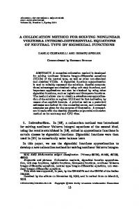
Numerical results have also been obtained for unsteady flow past a stationary cylinder at Re = 100. The same boundary conditions that were applied to the NACA-0012 airfoil were also applied to this case. Figures 9 and 10 show the mesh, vorticity contours and time history of the lift coefficient. Again, we run a 3rd order method, corresponding to a mesh with 39,339 DOF. The blockage caused by the presence of the cylinder is 2.5%. The pseudo time step in the LU-SGS scheme is 100x larger than that in the explicit scheme.
9 of 13 American Institute of Aeronautics and Astronautics
Figure 6. 2D NACA-0012 mesh: full (left), zoom (right).
Figure 7. 2D NACA-0012 at Re=1850: pressure (left), u-velocity (right).
Figure 8. 2D NACA-0012 at Re=1850: residual vs. pseudo iterations.
10 of 13 American Institute of Aeronautics and Astronautics
Furthermore, the increased stability offered by LU-SGS permits a 100x larger physical time step, while still capturing the transient process. Of course, the cost per physical iteration is higher for LU-SGS and mainly ∂Rc , the number of SGS-type sweeps performed, depends upon frequency of computing the cell Jacobian ∂Q c and the size of the cell matrix. For example, the cost per iteration associated with 3 SGS sweeps is roughly 5 times greater than the explicit scheme. In this test case, the cell Jacobian is computed every 5 physical iterations. For each time stepping technique, Tab. 4 shows the number of pseudo iterations, mmax , various sweep iterations, kmax = 1, 3, 6, 10, drag and lift coefficients, Strouhal numbers, and speedups in CPU time per shedding cycle. Figure 11 plots the residual against the total number of pseudo iterations, n · mmax , for each time stepping scheme. To give a fair comparison between RK33 and LU-SGS schemes, we look at the results associated with sweep iterations kmax = 3 because the levels to which the residuals drop are approximately equal. The speedup factor achieved by LU-SGS in this case is 8.5.
Figure 9. 2D Cylinder mesh; full (left), zoom (right).
Figure 10. 2D Cylinder at Re=100: vorticity (left) and CL (right).
11 of 13 American Institute of Aeronautics and Astronautics
Figure 11. 2D Cylinder at Re=100: residual vs. total number of pseudo iterations.
mmax kmax CL,rms ¯ CD (CD,rms ) St Speedup
RK33 10 0.231 1.354 (0.006) 0.162 1
LU − SGS 10 1 0.240 1.342 (0.006) 0.160 25.2
10 3 0.230 1.338 (0.006) 0.162 8.5
10 6 0.223 1.338 (0.006) 0.163 4.5
10 10 0.222 1.338 (0.006) 0.163 2.7
Table 4. 2D Cylinder at Re=100: drag/lift coefficients and Strouhal number.
IV.
Conclusion
The FR/CPR method with artificial compressibility and dual-time stepping is presented for solving incompressible flows on unstructured grids. We show that the implicit LU-SGS time stepping scheme is well suited to more quickly satisfy the divergence-free constraint of the continuity equation. The evaluation of viscous flux across each interface utilizes the BR2 method, which makes the stencil compact and allows for efficient inversion of the implicit operator within the LU-SGS framework. Implementation of the high-order method is verified by 2D steady Taylor-Couette flow and further solutions are validated with flow past a NACA-0012 airfoil at zero angle of attack and a cylinder. Results show speedup factors in CPU time of approximately 55 for steady flow past the airfoil at Re = 1850 and 8.5 for unsteady flow past a cylinder at Re = 100 using three SGS sweeps. Within this high-order framework, the LU-SGS scheme is proven effective for driving the solution to steady state in pseudo time in comparison to the RK33 scheme for the artificial compressibility treatment of the incompressible Navier-Stokes equations.
Acknowledgment The first author would like to greatly acknowledge The George Washington University and the Department of Mechanical and Aerospace Engineering for financial support under the GW Presidential Merit Fellowship.
12 of 13 American Institute of Aeronautics and Astronautics
References 1 Huynh, H. T., “A reconstruction approach to high-order schemes including discontinuous Galerkin for diffusion,” AIAA Paper , AIAA-2009-403, 2009. 2 Huynh, H. T., Wang, Z. J., and Vincent, P. E., “High-order methods for computational fluid dynamics: A brief review of compact differential formulations on unstructured grids,” Computers and Fluids, Vol. 98, 2014, pp. 209–220. 3 Chorin, A. J., “A numerical method for solving incompressible viscous flow problems,” Journal of Computational Physics, Vol. 135, No. 2, 1997, pp. 118–125, reprinted from Vol. 2(1), 1967, pp. 12-26. 4 Jameson, A., “Time dependent calculations using multigrid, with applications to unsteady flows past airfoils and wings,” AIAA, AIAA-1991-1596. 5 Wang, Z. J., Fidkowski, K., Abgrall, R., Bassi, F., Caraeni, D., Cary, A., Deconinck, H., Hartmann, R., Hillewaert, K., Huynh, H. T., Kroll, N., May, G., Persson, P.-O., v. Leer, B., and Visbal, M., “High-order CFD methods: current status and perspective,” International Journal for Numerical Methods in Fluids, Vol. 00, 2012, pp. 1–42. 6 Reed, W. H. and Hill, T. R., “Triangular mesh methods for the neutron transport equation,” Los Alamos Scientific Laboratory Report, LA-UR-73-479, 1973. 7 Kopriva, D. A., “A staggered-grid multidomain spectral method for the compressible Navier-Stokes equations,” Journal of Computational Physics, Vol. 143, 1998, pp. 125–158. 8 Liu, Y., Vinokur, M., and Wang, Z. J., “Discontinuous spectral difference method for conservation laws on unstructured grids,” Journal of Computational Physics, Vol. 216, 2006, pp. 780–801. 9 Wang, Z. J., Zhang, L., and Liu, Y., “Spectral (finite) volume method for conservation laws on unstructured grids IV: Extension to two-dimensional Euler equations,” Journal of Computational Physics, Vol. 194, No. 2, 2004, pp. 716–741. 10 Huynh, H. T., “A flux reconstruction approach to high-order schemes including discontinuous Galerkin methods,” AIAA Paper , AIAA-2007-4079, 2007. 11 Wang, Z. J. and Gao, H., “A unifying lifting collocation penalty formulation including the discontinuous Galerkin, spectral volume/difference methods for conservation laws on mixed grids,” Journal of Computational Physics, Vol. 228, No. 21, 2009, pp. 8161–8186. 12 Vincent, P. E., Castonguay, P., and Jameson, A., “A new class of high-order energy stable flux reconstruction schemes for triangular elements,” Journal of Scientific Computing, Vol. 51, No. 1, 2012, pp. 224–256. 13 Wang, Z. J., “High-order methods for the Euler and Navier-Stokes equations on unstructured grids,” Progress in Aerospace Science, Vol. 43, 2007, pp. 1–41. 14 Shahbazi, K., Fischer, P. F., and Ethier, C. R., “A high-order discontinuous Galerkin method for the unsteady incompressible Navier-Stokes equations,” Journal of Computational Physics, Vol. 222, No. 1, 2007, pp. 391–407. 15 Nguyen, N. C., Peraire, J., and Cockburn, B., “A hybridizable discontinuous Galerkin method for the incompressible Navier-Stokes equations,” AIAA, AIAA-2010-362, 2010. 16 Liang, C., Chan, A. S., and Jameson, A., “A p-multigrid spectral difference method for incompressible Navier-Stokes equations,” Computers and Fluids, Vol. 51, 2011, pp. 127–135. 17 Jameson, A. and Yoon, S., “LU implicit schemes with multiple grids for the Euler equations,” AIAA Paper , AIAA-860105, 1986. 18 Liang, C., Kannan, R., and Wang, Z. J., “A p-multigrid spectral difference method with explicit and implicit smoothers on unstructured triangular grids,” Computers and Fluids, Vol. 38, 2009, pp. 254–265. 19 Sun, Y., Wang, Z. J., and Liu, Y., “Efficient implicit non-linear LU-SGS approach for compressible flow computation using high-order spectral difference method,” Communication of Computational Physics, Vol. 5, No. 2-4, 2009, pp. 760–778. 20 Parsani, M., Ghorbaniasl, G., Lacor, C., and Turkel, E., “An implicit high-order spectral difference approach for large eddy simulation,” Journal of Computational Physics, Vol. 229, 2010, pp. 5373–5393. 21 Haga, T., Sawada, K., and Wang, Z. J., “An implicit LU-SGS scheme for the spectral volume method on unstructured tetrahedral grids,” Communication of Computational Physics, Vol. 6, No. 5, 2009, pp. 978–996. 22 Shu, C.-W. and Osher, S., “Efficient implementation of essentially nonoscillatory shockcapturing schemes,” Journal of Computational Physics, Vol. 77, No. 2, 1988, pp. 439–471. 23 Rusanov, V. V., “Calculation of interaction of non-steady shock waves with obstacles,” Journal of Computational and Mathematical Physics USSR, Vol. 1, 1961, pp. 267–279. 24 Bassi, F. and Rebay, S., “A high-order discontinuous Galerkin method for compressible turbulent flows,” Discontinuous Galerkin methods: Theory, Computation, and Application, B. Cockburn, G. Karniadakis and C.-W. Shu, editors, Lecture notes in computational science and engineering, Springer, 2000, pp. 77–88.
13 of 13 American Institute of Aeronautics and Astronautics