The control of induction machine as integrated starter generator forms an interesting academic and ... generator functions in a single electric machine, instead of.
41
Nature & Technology
A high performance svm-dtc scheme for induction machine as integrated starter generator in hybrid electric vehicles Mohamed Bounadja,a Ahmed Wahid Belarbi,b Bachir Belmadania a b
Department of Electrotechnics, University Hassiba Benbouali of Chlef, BP151 Hay Essalem, Chlef (02000), Algeria
Faculty of Electrical Engineering, University of Sciences and Technology of Oran, BP1505 El-M’naouer, Oran (31000), Algeria
Abstract The control of induction machine as integrated starter generator forms an interesting academic and practical solution for future 42V PowerNet in hybrid electric vehicles. In this paper, an alternative control method is proposed for induction machine, which enjoys the advantages of stator vector control and direct torque control and avoids some implementation difficulties of either of the two control methods. To obtain a fixed switching frequency and low torque ripple, the proportional–integral controllers and space vector modulation technique are used. Furthermore, by controlling the machine’s torque, the required DC-bus voltage can be regulated within the 42V PowerNet specifications. Keywords: Induction machine ; direct torque and flux control ; vector control ; integrated starter generator (ISG) ; space vector modulation (SVPWM) ; 42V PowerNet
1. Introduction In recent years, integrated starter generator (ISG) has attracted significant research interest in order to provide greater electrical generation capability and to improve the fuel economy and emissions of modern hybrid electric vehicles. This innovated machine has been proposed as solution to implement the new PowerNet architecture in vehicles, an increase of the electrical bus voltage from 14V to 42V [1-3], to cope with the increasing electric power demand. The ISG system combines both starter and generator functions in a single electric machine, instead of having two separate machines, as is the case in conventional vehicles [4]. In this context, the machine selection and design are being investigated intensively to meet the challenges of the 42V PowerNet [5-7]. The machine designed for an ISG should be capable of providing a high starting torque to crank the engine in short starting time. After the engine is started above the idle speed, the ISG machine operates in generation state to supply a constant voltage for charging the battery of automobile. Also, the machine controller is one of the most important aspects of any vehicular drive system including the ISG. Therefore, rotor field oriented control (RFOC) of AC machines appears to have drawn much interest, and it Revue « Nature et Technologie ». n° 02/Janvier 2010. Pages 41 à 47
was natural to extend to the ISG application [8-13]. However, RFOC has several disadvantages such as high computational requirement, high parameter dependence and speed signal for the coordinate transformation. Also, the direct torque control (DTC) technique has gained wide acceptance in motor drive [14,15], and has been considered for the ISG application [16]. Although the DTC is a simple control scheme with low computational requirement and has merits like inherent sensorless operation and reduced parameter sensitivity, it has some drawbacks such as operation with variable switching frequency and large torque ripple, due to the hysteresis control and the switching table method [17,18]. To overcome these problems, the variable switching frequency problem and the torque ripple can be addressed by Proportional-Integral (PI) controllers plus space vector modulation (SVM) [1923]. Those reported works was extended to an ISG system [24,25]. However, the calculation of the voltage command vector requires the derivative of the stator flux vector, which is kept moving and can be a potential source of errors. This paper presents an alternative scheme for torque and stator flux control of an induction machine for ISG application. The proposed scheme investigates the basic DTC idea, which considers the torque of induction machine proportional with the slip frequency if the amplitude of stator flux vector is kept constant. For that, stator vector control (SVC) is used to avoid the requirement of the
42
Revue « Nature & Technologie » n° 02/Janvier 2010
derivative of stator flux vector and to develop the relationships between the controlled variables and the machine torque. Hence, with the combined SVC and DTC methods, the torque and stator flux vector can be regulated with PI controllers, and the required voltage vector can be applied to the induction machine by the space vector modulation (SVM). The estimation of the torque and stator flux is based on voltage mode estimator with minimized sensors numbers. In fact, speed sensor is eliminated and only DC-bus voltage sensor and two AC current sensors are needed. As the torque of induction machine is controlled, the DC-bus voltage can be regulated to meet the specification of the 42V hybrid electric vehicle. This paper is organised as follows: the proposed torque and stator flux control principle is detailed and developed in Section 2. The ISG based induction machine control is described in Section 3. The effectiveness of the approach is examined in Section 4 using computer simulation experiments. Finally, the conclusion is drawn in Section 5.
The dynamic model of the induction machine can be represented in the (d,q) frame as:
dΦ ds − ω s Φ qs dt dΦ qs + + ω s Φ ds dt
v qs = Rs i qs
dΦ dr − ω sl Φ qr dt dΦ qr + + ω sl Φ dr dt
Φ ds = Ls i ds + Lsr idr
Φ dr = Lr i dr + Lsr i ds
(
Tem = p Φ ds i qs − Φ qs i ds
(6)
Then, (1) and (5) can be simplified to: dΦ s dt + ωsΦ s
v ds = Rs ids + v qs = Rs iqs
(7)
Tem = pΦ s i qs
idr =
(8)
1 (Φ s − Ls ids ) Lsr
(9)
L = − s iqs Lsr
Φ dr =
Lr (Φ s − σLs ids ) Lsr
Φ qr = − (2)
(4)
Φ qr = Lr i qr + Lsr i qs
Φ ds = Φ s ; Φ qs = 0
(1)
(3)
Φ qs = Ls i qs + Lsr iqr
The stator field-orientation method is based on the alignment of stator flux vector with d-axis and setting the stator flux to be constant equal to its rated value, which means:
iqr
0 = Rr i dr + 0 = Rr i qr
2.1. Stator flux control
Next, the rotor currents and rotor fluxes can be expressed as:
2. The proposed direct torque and flux control
v ds = Rs i ds +
resistances, Ls, Lr are the stator and rotor inductances, Lsr is the mutual inductance, and p is the number of pole pairs.
(10)
σLr Ls iqs Lsr
Therefore, by substituting (9) and (10) in (2) and considering the Laplace operator (s = d/dt), (11) can be obtained:
(
Φ s (s ) = (1 + σTr s )I ds + σTr I qs ω sl
)1 +LTs s r
1 Tω I qs (s ) = Φ s − σI ds r sl Ls 1 + σTr s
(11)
Thus, the stator voltages become:
)
(5)
In which the known entities are: the stator currents (ids,iqs) and the input voltages (vds,vqs). The unknown, who need to be estimated, are: the stator fluxes (Φds,Φqs) and the rotor fluxes (Φdr,Φqr), the electromagnetic torque Tem and the slip angular speed ωsl = ωs – ωm, in which ωs and ωm are the synchronous and rotor angular speed respectively. (idr,iqr) are the rotor currents. Rs, Rr are the stator and rotor
Vds (s ) =
1 + (Tr + Ts )s + σTr Ts s 2 σRs Tr Φs − I qs ω sl Ts (1 + σTr s ) 1 + σTr s
Vqs (s ) = Rs I qs + ω s Φ s ≈ ω s Φ s
(12)
in which Ts = L s R s and Tr = Lr Rr are the stator and rotor time constants, and σ = 1 − L2sr (Ls Lr ) is the total leakage constant.
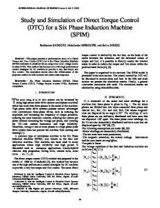
A high performance svm-dtc scheme for induction machine From (12), it can be seen that the stator flux can be regulated by the d–component of stator voltage. Fig. 1 shows the relationship between Φs and Vds; a second-order equivalent system with a disturbance Ed.
43 ωm(s) ωs(s)
Tem*
− GTem(s)
PI +−
Tem(s)
+
Ed(s) Φs* +
−
Vds(s)
PI
GΦs(s)
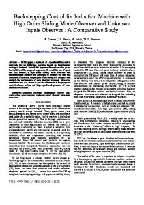
Φs(s) Fig. 2. Closed-loop control of electromagnetic torque.
+
−
where:
GTem (s ) = p
Fig. 1. Closed-loop control of stator flux.
Tr (1 − σ ) Φ s Ls 1 + 2σTr s *2
(17)
where:
GΦs (s ) =
Ts (1 + σTr s )
1 + (Tr + Ts )s + σTr Ts s
3. ISG based induction machine control
2
σRs Tr Ed (s ) = − I qs ω sl 1 + σTr s
(13)
2.2. Electromagnetic torque control From (11), the q-component of stator current can be expressed as: I qs (s ) =
Φ s ω sl Tr (1 − σ ) 2 Ls (1 + σTr s ) + (σTr ω sl (s ))2
(14)
Hence, the expression (8), giving the electromagnetic torque, becomes:
Tem (s ) = p
Φ s ω sl Tr (1 − σ) Ls (1 + σTr s)2 + (σTr ω sl )2 2
(15)
From the basic DTC principle, if the amplitude of stator flux vector is kept constant and equal to its reference value Φs*, the torque of induction machine is proportional with the slip angular speed. Therefore, with the small values of the slip angular speed and σTr