performance than the search-based algorithms proposed in the related work. .... cussed in Section 6. Section 7 .... Given the rendering viewpoint vs, the server processes the ..... video and streaming to both Nokia N800 tablet and iPhone.
A High-Quality Low-Delay Remote Rendering System for 3D Video Shu Shi, Mahsa Kamali, Klara Nahrstedt, John C. Hart, and Roy H. Campbell Department of Computer Science University of Illinois at Urbana-Champaign 201 N Goodwin Ave., Urbana, IL 61801, USA
{shushi2, mkamali2, klara, jch, rhc}@illinois.edu ABSTRACT
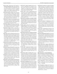
(a)
As an emerging technology, 3D video shows a great potential to become the next generation media for tele-immersion. However, streaming and rendering this dynamic 3D data in real-time requires tremendous network bandwidth and computing resources. In this paper, we build a remote rendering model to better study different remote rendering designs and define 3D video rendering as an optimization problem. Moreover, we design a 3D video remote rendering system that significantly reduces the delay while maintaining high rendering quality. We also propose a reference viewpoint prediction algorithm with super sampling support that requires much less computation resources but provides better performance than the search-based algorithms proposed in the related work.
(c)
(d)
(b)
Figure 1: (a) Camera Setup for 3D Video Capturing; (b) BumbleBee 2 Stereo Camera (c) Point Cloud Based 3D Video (d) Mesh Based 3D Video
Categories and Subject Descriptors H.5.1 [Multimedia Information System]: Video
background, just like dealing with computer graphics. Although different approaches to 3D video have been proposed [22, 11, 23], all share the same feature that 3D video is comprised of sequential frames and each frame is built from the static images that are captured by cameras from multiple viewpoints. For example, Figure 1 illustrates how 3D video is generated in our tele-immersion system, TEEVE [2]. Multiple stereo cameras [1] are calibrated and placed in different positions to capture the depth image of real-world objects. The depth images from different cameras are collected to construct either a point-cloud [23] or triangle meshes [12] as the 3D video frame in real-time. The system is currently capable of generating up to 20 3D video frames per second. There are two major challenges for rendering 3D video on mobile devices. First, 3D video requires very large network bandwidth for transmission. The 3D video stream size is proportional to the total number of capturing cameras. According to [23], a quality real-time immersive communication using point cloud based 3D video needs a Gbps bandwidth, which is far beyond the capacity of wireless networks (cellular 3G/4G, Wi-Fi 802.11b/g) supported by most mobile devices. Second, although the most advanced smartphones are currently equipped with hardware to support OpenGL ES, rending 3D video frames is a very computation intensive task. Moreover, the rendering of every frame has a strict deadline because the frame expires when the next frame arrives. In our previous work [20], we proposed to use remote rendering system for real-time 3D video rendering on mobile
General Terms Design, Measurement
Keywords 3D Video, Remote Rendering, 3D Warping, Mobile Devices
1.
INTRODUCTION
3D video has attracted more and more research interests in recent years due to its bright future in the next generation tele-communication and tele-immersion applications. In this paper, we study how to design a remote rendering system for 3D video rendering on mobile devices. The 3D video referred here is different from the stereo video played in 3D movie theaters. The stereo video provides the audience a 3D depth illusion by forcing different eyes to see different views, while the 3D video in our research, also named as the free viewpoint video [21], allows the audience to interactively select different rendering viewpoints or change different virtual
Permission to make digital or hard copies of all or part of this work for personal or classroom use is granted without fee provided that copies are not made or distributed for profit or commercial advantage and that copies bear this notice and the full citation on the first page. To copy otherwise, to republish, to post on servers or to redistribute to lists, requires prior specific permission and/or a fee. MM’10, October 25–29, 2010, Firenze, Italy. Copyright 2010 ACM 978-1-60558-933-6/10/10 ...$10.00.
601
Wireless Network
Rendering Server
Image Frame After Rendering R1
…
Fi Fi+1
Model Filtering more
Double Warping
Environment Map
Network Bandwidth and Computation on Client
less
Fj
……
Figure 3: Remote Rendering Systems
First frame processed at the updated Rendering Viewpoint
based on what type data is sent from the rendering server to the client: the model-based approach and the image-based approach (Figure 3). In a model-based remote rendering system, the server transmits the original or simplified 3D models (meshes or point cloud) to the client. The client needs to have enough local graphical capabilities to render received models. On the contrary, the image-based remote rendering system depends on the server to render 3D models and requires no special graphical computation on the client. In this section, we briefly review the designs in both categories and we will compare their pros and cons in Section 3.3. Model Forwarding & Filtering: Strictly speaking, model forwarding is not a remote but local rendering approach. The server forwards the original 3D model based upon request and leaves all 3D rendering to the client. Model filtering requires the server to filter the data before transmission. A subset of original data or the simplified lowresolution 3D model are sent to the client for rendering. Such systems [10, 17] have been mainly designed for medical image visualization. Point-Based Rendering: Duguet and Drettakis [9] suggested using a powerful server to transform the mesh-based graphic model to a point-based representation, the density of which is decided by the screen size of mobile devices. Since most mobile devices have only small screens, rendering the simplified point-based model requires much less computing resources on mobile devices compared with original meshbased rendering. Image Streaming: In this simple remote rendering approach, the server renders the 3D model at the viewpoint specified by the client. The generated 2D image can be efficiently compressed with mature image/video coding tools for network transmission. The client simply displays the received image frame. The only disadvantage of this approach is the interaction delay as we have mentioned in Section 1. Lamberti and Sanna [13] surveyed on image streaming systems and discussed in depth about timing factors that affect system performance. Environment Map: Chen [6] first introduced environment map to remote rendering in his Virtual VR system. The server generates an environment map (e.g., a panoramic cylindrical projection map) of the 3D scene. The environment map contains enough information to represent the scene from any viewpoint at a fixed position. Thus it allows the client to pan and tilt the virtual camera freely in a wide range. Boukerche and Pazzi [4] studied how to stream environment maps to mobile devices in a remote virtual world walk-through system.
Figure 2: Interaction Delay devices. A powerful workstation is introduced as the rendering server (proxy) that pre-renders the 3D video frame to 2D images for mobile clients. The remote rendering system solves both bandwidth and computation problems, but a new problem of interaction delay is brought into the scope. Since 3D video allows the viewer to interactively change the rendering viewpoint, when the mobile client receives a user interaction request, it has to forward the request to the proxy server and waits at least a round trip network delay for the future frames that are processed at the updated rendering viewpoint. Figure 2 gives an intuitive illustration. Since the interaction delay has great impacts on the user experience of interactive applications [8], we must consider how to reduce the interaction delay to an acceptable level when designing a remote rendering system. In this paper, we build a remote rendering model to study different remote rendering systems in literatures and interaction delay problems. We propose using a new reference viewpoint prediction algorithm for 3D warping based remote rendering system. We prove that our algorithm requires far less computation resources but provides much better performance in terms of viewpoint range (explained in Section 3.4) than the search-based algorithms suggested in [20]. We believe the work of this paper makes two major contributions. First, we study the remote rendering system from a new perspective and transform the network-related interaction delay problem into a content-based reference prediction problem. Second, we find a computation efficient method to create an image-based representation for any complex graphic models. The image-based representation is sufficient to support highquality rendering of the original model when the rendering viewpoint changes in a limited range. Besides, we will also discuss how our remote rendering system can be extended to support general graphic content, such as games. In the rest of the paper, we first review previous remote rendering designs in Section 2. We define the remote rendering model. Section 4 concentrates on reference viewpoint prediction algorithm and Section 5 evaluates the algorithm performance. Issues of optimization and extension are discussed in Section 6. Section 7 concludes the paper.
2.
Image Streaming
…
…
First Result frame at the updated Rendering Viewpoint
3D Warping
F3
…
…
Rj
Point-based Rendering
Image Based
F2
Ri+1 …
Interaction Delay
…
Ri
Model Forwarding
3D Video Frame F1
…
R3
Model Based
Video Source
…
R2
Wired Network
Time
Mobile Devices
RELATED WORK
In general, previously proposed server-client based remote rendering systems can be divided into two major categories
602
there will be a duration when the rendering viewpoint stored on the server is inconsistent with that on the client. We now define the system behaviors described above as follows. We use S to denote the source 3D content. If the source content is static, S refers to the whole set of 3D models (can be either meshes or point clouds). If the source content is dynamically updated (like 3D video), S refers to only one frame of the dynamic content, and FPSsrc is used for the update rate of the source content. In this case, S 1 . The rendering viewpoint v is a has a lifespan of FPS src set of three three-dimensional vectors: {pos, dir, up}, which stand for camera position, look-at direction, and up direction. Due to the possible viewpoint inconsistency between the server and the client, vs and vc are used to denote the rendering viewpoint on the server and client, respectively. Given the rendering viewpoint vs , the server processes the source content S to generate a reference frame Rs .
Figure 4: Server-Client Remote Rendering System Architecture 3D Warping: 3D warping proposed by McMillan [15] is a classic image-based rendering technique adopted in many remote rendering applications [5, 3]. Compared with the image streaming approach, the server only generates one more depth map of the rendered scene, but the client can warp the received depth image (including both color and depth maps) to arbitrary viewpoint. 3D warping solves the problem of interaction delay but brings the new problem of warping error. Double Warping: Mark [14] first suggested double warping. The idea of using multiple image to compensate holes appeared even before 3D warping [7] . Besides the depth image rendered at the current viewpoint, the server also generates another depth image at a selected reference viewpoint, and sends both depth images to the client. The client runs 3D warping twice for two depth images and composite the results. The double warping can greatly reduce the warping errors caused by single warping if the reference viewpoint is appropriately selected. Shi [20] proposed algorithms to select the optimal viewpoint for the remote rendering system using double warping. Before we discuss more about warping error and double warping, we first introduce our remote rendering model.
3.
Rs = proc s(S, vs ) If the source content is dynamic, there is an extra time constraint that proc s must finish before S expires. time s(proc s)
on the server. The client can warp the depth image to arbitrary vc . The function warp(vs , vc ) used in Table 1 means to warp the depth image generated at vs , that is < Dsref , depths > to the new viewpoint vc . The complexity of warping function depends only on the image resolution. The penalty probability of 3D warping depends on warping errors. For a given vs , there exists a viewpoint set Vwarp n o Vwarp = ∀vi , diff(warp(vs , vi ), Diref ) < errresp (9)
(6)
and time penalty can be represented as: time penalty = p · (rtt +
E(kRc)k) ) BW
if vc .pos = vs .pos
(7)
where p is the penalty probability of that Dcs is not similar to Dcref “ ” p = P diff(Dcs , Dcref ) ≥ errresp (8) and E(kRc)k) is the average size of compressed reference frames. Due to Eq (3), time c(proc c) is considered as a fixed portion, and we focus on reducing time penalty. E(kRc)k) is limited by Eq (2), but rtt can vary significantly BW frame by frame in different networks. We find that the penalty probability is not affected by network. We can reduce p with different remote rendering system designs, so that the response time is also reduced. In the rest of this section, we will use this model to analyze the remote rendering designs reviewed in Section 2 and find out what we can improve for 3D video remote rendering. For simplicity, we may omit the encoding/decoding procedure in some discussions. In that case, we consider Rs′ = Rs .
The penalty probability can be reduced to probability that vc does not fall into Vwarp . Thus the response time of 3D warping is actually decided by the size of Vwarp . Double Warping can provide a Vdwarp that is larger than Vwarp . n o Vdwarp = ∀vi , diff(dwarp(vs , vp , vi ), Diref ) < errresp (10) Compared with 3D warping, the larger Vdwarp increases the probability that vc falls into, and can further reduce the penalty probability and response time. The function in Eq
604
System Design Model Forwarding Model Filtering Point Rendering Image Streaming Environment Map 3D Warping Double Warping System Design Model Forwarding Model Filtering Point Rendering Image Streaming Environment Map 3D Warping Double Warping System Design Model Forwarding Model Filtering Point Rendering Image Streaming Environment Map 3D Warping Double Warping
Table 1: Summary of Remote Rendering Systems proc s(S, vs ) Ref. Frame Rs proc c(Rs , vc ) return S S render(S, vc ) apply filter to S S′, S′ ⊆ S render(S ′ , vc ) transform S to point cloud P render(P, vc ) render(S, vs ) Dsref display only if vc .pos = vs .pos proj(env map(S, vs ), vc ) generate environment map env map(S, vs ) else do nothing if vc = vs return Dsref ref render(S, vs ), extract depths < Ds , depths > else warp(vs , vc ) render(S, vs ), extract depths if vc = vs return Dsref ref < Ds , depths > select reference viewpoint vp elseif vc = vp return Dpref < Dpref , depthp > render(S, vp ), extract depthp else dwarp(vs , vp , vc ) time(proc s) time(proc c) kRs k 0 1 × time c(render), ∝ kSk ∝ kSk depends on filtering algo. 1 × time c(render), ∝ kS ′ k ∝ kS ′ k depends on point transformation algo. 1 × time c(render), ∝ kP k ∝ kP k 1 × time s(render) 0 ∝ screen resolution 6 × time s(render) ∝ screen resolution ∝ screen resolution 1 × time s(render) ∝ screen resolution ∝ screen resolution time s(ref viewpoint sel) + 2 × time s(render) ∝ screen resolution ∝ screen resolution diff (Ds , Dref Penalty Probability s ) 0 0 < errdisp P (diff(render(S ′ , vc ), Dcref ) ≥ errresp ) < errdisp P (diff(render(P, vc ), Dcref ) ≥ errresp ) 0 1 0 P (vc .pos 6= vs .pos) n o 0 P (vc ∈ / Vwarp ), where Vwarp = ∀vi , diff(warp(vs , vi ), Diref ) < errresp n o 0 P (vc ∈ / Vdwarp ), where Vdwarp = ∀vi , diff(dwarp(vs , vp , vi ), Diref ) < errresp
(10), dwarp(vs , vp , vc ) warps both < Dsref , depths > and < Dpref , depthp >, to the new viewpoint vc and composite the result images. The overhead is that the server needs to select a reference viewpoint vp and generate two depth images for both vs and vp .
• Translate: Change pos horizontally or vertically. • Orbit: Move pos along a circle and keep dir pointing to the center of the circle. When the client is at pan & tilt mode, the server generates an environment map as the reference frame. When the client is at other interaction modes (translate, orbit, or zoom), we take the approach of double warping. Since environment map already achieves minimum response time for pan & tilt (the penalty probability is 0 because pan & tilt does not change pos), we focus on how to improve double warping in this paper. According to Table 1, we can reduce the response time of double warping by increasing Vdwarp . Thus, we change the problem of designing a 3D video remote rendering system to an optimization problem: how to find the reference viewpoint vp that maximizes kVdwarp k (kVdwarp k represents the number of viewpoints contained in Vdwarp ). Before studying how vp should be selected, we take a look at viewpoints contained in Vdwarp . We assume that all viewpoint changes are discrete. vc can be represented by the following equation because it is transformed from vs .
3.4 3D Video Remote Rendering According to the introduction before, remote rendering 3D video for mobile devices has three challenges. First, the huge size of the original 3D video streams makes it very difficult to transmit through wireless networks and render on mobile devices in real-time. Second, the dynamic nature of 3D video requires both the server and the client to intensively compute every 3D video frame before fixed deadline. Third, the wireless networks used by mobile devices are not reliable and can cause long rtt. Obviously, the imagebased approaches that require less network bandwidth and client computation are more appropriate for 3D video rendering than model-based approaches. Considering the pros and cons of each image-based approach discussed above, we believe a hybrid solution can be the best for 3D video. Due to the setup of 3D video capturing (Figure 1(a)), only a limited range of viewpoints are necessary for 3D video rendering. Thus the 3D video interaction can be simplified to four modes [20, 6] and we list here how each interaction mode changes viewpoint.
vc = vs + c · T where T is the vector for one step viewpoint change (T has different values for different interaction modes). We only care about the viewpoint vi = vs + i · T because they are candidates for vc . Given the reference viewpoints vs and vp (vp = vs + p · T , p > 0), intuitively, we think only the
• Zoom: Move pos along dir • Pan & Tilt: Change dir horizontally or vertically.
605
Occlusion Exposure
viewpoint vi with 0 ≤ i ≤ p can benefit from double warping. If i < 0 or i > p, the image quality of dwarp(vs , vp , vi ) can be no better than warp(vs , vi ) or warp(vp , vi ). This intuitive conclusion has been supported in [14]. Therefore, for the study of double warping in the rest of this paper, we omit the viewpoints that do not benefit from double warping and consider Vdwarp (vs , vp ) ⊆ [vs , vp ], and
Insufficient Sampling
Surface
[vs , vp ] = {vi |vi = vs + i · T, 0 ≤ i ≤ p} Thus kVdwarp (vs , vp )k ≤ k[vs , vp ]k C1
k[vs , vp ]k is the size of [vs , vp ], also referred as the viewpoint range of two reference viewpoints. We can further simplify the 3D video rendering problem to find the reference viewpoint vp that max {kVdwarp (vs , vp )k = k[vs , vp ]k} p
Figure 5: Occlusion Exposure and Insufficient Sampling
(11) state of the art [16], but, too slow for real-time applications. Depth filter [18] and splat warping [14] are only useful for the small holes caused by insufficient sampling. Super view warping [3] and wide field-of-view warping [14] can partially solve the occlusion exposure but do not help with insufficient sampling at all. Double warping [14, 20], view compensation [3], and LDI [19] are effective for both holes. Although using different names, both view compensation and LDI are actually the same as double warping in nature. Images from different viewpoints are used to compensate warping errors. However, double warping best suits a 3D video remote rendering system because it does not need offline processing (LDI) or interactive communication (viewpoint compensation). Figure 6 illustrates how double warping works. We use a static bunny model instead of 3D video frames for demonstration in this paper because the holes introduced in 3D video capturing (Figure 1) can be misleading when we analyze the holes caused by 3D warping.
None of previous researches thoroughly solved this problem. [20] suggested using search to find vp that satisfies Eq (11). However, it requires too much computation on the server and contradicts with the real-time requirement in Eq (3). In the next section, we introduce our reference viewpoint prediction algorithm and show how we can generate reference frames efficiently for double warping.
4.
C2
ENHANCED DOUBLE WARPING
In this section, we analyze how warping errors are generated and show how double warping can be improved with a computationally efficient reference viewpoint prediction algorithm.
4.1 Warping Error Analysis The 3D warping algorithm takes a reference depth image (including both color and depth maps), the reference viewpoint at which the depth image is generated, and the target viewpoint as input, and computes the color image at the target viewpoint as output. For every pixel (u1 , v1 ) in the reference depth image, the algorithm calculates the image coordinate (u2 , v2 ), and copies the color from (u1 , v1 ) to the pixel (u2 , v2 ) in the target image. The algorithm is very efficient. It processes each pixel only once and the image coordinate calculation just takes a few arithmetic operations. Refer to [15] for more details about 3D warping. 3D warping is not perfect. “Hole” artifacts are introduced when the scene objects that do not exist in the input image become visible to the new rendering viewpoint. There is no pixel in the input image to reference when drawing the new image. It has been referred as the exposure problem. However, by looking into how exactly holes are generated, we find that holes can actually be divided into two categories. The first category of holes are caused by occlusion exposure. The objects that are completely occluded or out of view range in the input image become exposed. The second category of holes is named as insufficient sampling. It happens when warping a small resolution image to a large resolution, or more frequently, on a surface with varying gradient. Figure 5 shows an example of these two types of warping errors. The classification also helps to understand previous techniques proposed to fill holes. Recent progress on sparserepresentation and data-driven hole filling appears to be
4.2 Reference Viewpoint Prediction From the above analysis of warping holes, we find that the holes are generated when there are not enough pixels in the reference image. Double warping can fill holes because the pixels missing in one reference image can be found in the other one. Therefore, given one reference viewpoint (vs , also referred as main reference viewpoint), the expected reference viewpoint vp should provide pixels missing in the main reference image to compensate holes generated by warping. We try to answer the following two questions first. Which viewpoints can serve to compensate most insufficient sampling holes caused by warping the depth image at vs ? Which viewpoints can serve to compensate most occlusion exposure holes of the depth image at vs ? Intuitively, for the first question, we can warp the main reference frame to all possible target viewpoints and find the viewpoints which generate the insufficient sampling hole with the largest size. These viewpoints are the best candidates because they provide most pixels to fill insufficient sampling holes. For the second question, we try to find the viewpoints which are far away from the the main reference viewpoint so that two reference viewpoint do not overlap. Therefore, the intersection of two viewpoint sets can be the best candidate of the reference viewpoint we try to predict. We start from the analyzing translate mode. Assuming the viewpoint only translates to right horizontally along the
606
(a)) (a
(c)
(b)
V60
V30
V0 (d)
(e)
(g)
(h)
(j)
(k)
(f)
(i)
(l)
Figure 6: (a)(b)(c) Color maps rendered at viewpoints v0 ,v30 , and v60 ; (d)(e)(f ) Depth map of the image rendered at viewpoint v0 ,v30 , and v60 ; (g) Image warped from v0 to v30 ; (h) Image double warped from v0 and v60 to v3 0; (i) Image warped from v60 to v30 ; (j)(k)(l) The difference between (g)(h)(i) and (b), respectively
B
f is the distance between the center-of-projection and the image plane. The warping holes can be generated between X and Y , if bi −ai ≥ b0 −a0 , and the hole size is represented by „ « 1 1 h=T ·f ·i − (12) da db
A db da
a0 f
Since T, f, da , db are all know parameters, the hole size h is a only decided by i. Therefore, if da < db , the warping from C0 to Ci can generate a hole between X and Y , and the hole has the maximum size hmax when the viewpoint moves to Cimax where the projection of X reaches the left boundary of the image plane.
ai
b0
bi V0
i .T
Vi
imax = Figure 7: Warping Hole Size Analysis
„ « da hmax = a0 1 − db
axis that is parallel with the image plane, the viewpoint v can be represented by the center-of-projection C in this case. As shown in Figure 7, object points X and Y are visible to the viewpoint at C0 , and the image coordinates are a, b, respectively. Since there is no movement in the vertical direction, we use only a0 and b0 to denote the projection of X and Y on the image plane. da and db are the depth value of X and Y . For any new viewpoint
(13)
(14)
Cimax is also the farthest viewpoint from C0 that can help compensate holes caused by insufficient sampling between X and Y . We select this viewpoint as one candidate of the reference viewpoint to predict. We propose our reference prediction algorithm in Table 2. The general idea is to calculate hmax and imax for every adjacent pixels in the image if they both have valid depth values. If hmax is large enough to create a hole, we add corresponding imax to the candidate list. The algorithm output vp is elected from the candidate list. Conservatively, the minimum value in the candidate list should be selected as vp so that all possible insufficient sampling warping errors can be covered. However, since the goal of our system design is to maximize the reference viewpoint vp rather than
Ci = C0 + i · T, i > 0 where T is the unit vector of camera translation, ai and bi are the new image coordinates of X and Y . We can calculate ai and bi as: ai = a0 −
da · a 0 T ·f
i·T ·f i·T ·f , bi = b0 − da db
607
Table 2: Reference Viewpoint Algorithm ` f ocPrediction ´ T f = Tunit · width / tan 2 2 < img0 , d0 > = render(S, C0 ) FOR u = 1 TO width FOR v = 1 TO height IF d0 (u, v) ≤ 0 CONTINUE END IF u 6= width && d0 (u + 1, v) ≤ 0 CONTINUE END IF u 6= width hmax = u · (1 − d0 (u, v)/d0 (u + 1, v)) IF hmax < 0.5 CONTINUE END END imax = u · d0 (u, v)/T f add to list(candidate list, imax ) END END RETURN kth-min(candidate list)
Table 3: Reference Viewpoint Prediction Algorithm with Super Sampling ` ´ T f = Tunit · width / tan f2oc 2 2n 2n < img0 , d0 > = render(S, C0 , 2n × width, height)1 FOR i = 0 TO n − 1 n i img02 = down scale(img02 × , 2i × width, height)2 2n × 2i i d0 = down scale(d0 , 2 × width, height) END FOR u = 1 TO width FOR v = 1 TO height IF d10 (u, v) ≤ 0 CONTINUE END IF u 6= width && d10 (u + 1, v) ≤ 0 CONTINUE END IF u 6= width hmax = u · (1 − d10 (u, v)/d10 (u + 1, v)) i = ⌊log(hmax + 1)⌋ IF i < n (i+1) × 3 add resolution(img01 , u, v, img02 ) 2(i+1) × 1 add resolution(d0 , u, v, d0 ) END END imax = u · d1× 0 (u, v)/T f add to list(candidate list, imax ) END END RETURN kth-min(candidate list)
error free rendering, we can be more aggressive by selecting the kth-min value in the candidate list as the reference viewpoint. We will compare different k selections in the evaluation section. 100% 90% 80% 70%
The overhead of super sampling is that it increases the size of the reference frame and requires more network bandwidth for streaming. There are several improvements to overcome this. First, when the viewpoint is moving horizontally, it is not necessary to increase the vertical resolution. Second, we do not store the whole main reference frame in the larger resolution, but only add super sampling pixels to the pixel pairs which can cause small holes. Table 3 shows an improved version of reference viewpoint prediction algorithm with super sampling support. The algorithm is scalable up to 2n × width super sampling. Our reference viewpoint prediction algorithm is efficient. Except for the 3D rendering at the main reference viewpoint, which can be reused for reference frame generation, the rest part of the algorithm barely needs any computation. Adding super sampling requires more memory space to store depth images at multiple resolution and extra computation for downscaling. However, those memory and computation requests are both proportional to the image resolution, which is decided by the display screen size of the client device. The derived algorithm only applies when the viewpoint translates to right horizontally. For other directions (e.g., left, up, or down), the algorithm can be derived in a similar procedure but with different Eq (13)(14). Our algorithm can also be modified for different user interaction modes, such as orbit and zoom. However, the hole size function for those modes becomes more complicated than Eq (12). We need to approximate hmax and imax for different modes. The
60% 50% 40% 30% 20% 10% 0% 0.5
1
1.5
2
2.5
3
3.5
4
4.5
5
hmax
Figure 8: Cumulative Distribution of hmax
4.3 Super Sampling Because the algorithm neglects the size difference of holes, we are still not satisfied with the solution mentioned above. It is possible that a lot of imax candidates in the candidate list are generated by small holes. In order to verify this hypothesis, we calculate the cumulative distribution of hmax of the bunny model. Figure 8 indicates that 60% holes have the size less than 1. Therefore, we propose a super sampling approach which intends to fill small holes caused by insufficient sampling. We render the main reference depth image at a higher resolution for super sampling pixels. For example, rendering at a double size gives one more pixel to each adjacent pixel pair in the original resolution, which can potentially eliminate all insufficient sampling holes with hmax ≤ 1.
608
38
Table 4: Viewpoint Prediction Results Algorithm & Viewpoint PSNR Configuration Range (dB) w/o Super Sampling, k = 1 40 32.68 w/o Super Sampling, k = 5% 48 31.47 w/o Super Sampling, k = 15% 56 29.52 Optimal, w/o Super Sampling 52 30.27 w. Super Sampling, k = 1 49 32.12 w. Super Sampling, k = 5% 53 32.01 w. Super Sampling, k = 15% 63 31.88 Optimal, w. Super Sampling 91 30.04 Full Search 6 34.92 Fast Median Search 16 33.99
w/o Super Sampling w Super Sampling
36
PSNR
34
32
30
28
26
24 0
10
20
30
40
50
60
70
80
90
100
Reference View Point Position
Figure 9: Optimal Rendering Viewpoint Table 4 compares the viewpoint range calculated by our proposed algorithm with the optimal results derived from Figure 9. We select both algorithms with and without 2 × width super sampling support, and for each algorithm we select different kth-min. We also compare our results with the search-based algorithms (full search and fast median search) from [20]. Since the search algorithm takes very long time to calculate the optimal results, we add a time constraint to the algorithm execution by assuming the FPSsrc is 15 frame per second. All algorithms are forced to stop after 66 ms. Thus the results also reflect the computation complexity of different algorithms. For each algorithm execution, we record the predicted reference viewpoint vp and fP SNR (p). We can draw two conclusions from the results. First, when super sampling is not considered, the results of our reference prediction algorithm are far better than the results of search based algorithms, and close to the optimal value. According to Eq (6), it also indicates that the double warping remote rendering system using our new algorithms has lower interaction delay when compared with original system because the new viewpoint has a higher probability to fall into Vdwarp . Second, using super sampling can further increase the performance of our algorithm. However, our algorithm is conservative in prediction when super sampling is supported. It is mainly because we assume the 2 × width super sampling pixels can only remove holes with hmax ≤ 1. A more aggressive selection of hmax threshold or k can help generate some results closer to the optimal.
other parts of the algorithm and super sampling can apply to different user interaction modes without modification.
5.
EVALUATION
We have built the framework for remote rendering 3D video and streaming to both Nokia N800 tablet and iPhone in our previous work [20]. As a summary, the proxy server receives original 3D video, generates two depth images as the reference frame, and sends to the mobile client through 802.11g Wi-Fi. Only one mobile client is supported for now, and we achieve the frame rate up to 10 fps for the resolution of 320×240. Please refer to original paper for details on system setup and networking statistics. In this section, we mainly evaluate how our reference viewpoint prediction algorithm compares with previous search-based algorithms. We use the same bunny model shown in Figure 6 instead of noisy 3D video frames so that the PSNR results are more convincing. The 3D model is rendered at the resolution of 250×250. We first generate Figure 9 to find the optimal reference viewpoints as the baseline for further comparison. Let the main reference viewpoint vs = v0 . The x-coordinate indicates the viewpoint vx is x steps away from vs . The ycoordinate indicates the PSNR of the worst image that double warping can generate, or formally expressed as fP SNR (x) = min {∀vi ∈ [vs , vx ], psnr(dwarp(vs, vx , vi ))} The dashed line is the threshold of errresp in Eq (10). The red and blue lines stand for double warping with and without the support of super sampling pixels. We can observe that both lines remain in high PSNR region when x is relatively small. As x increases, the line that corresponds to double warping without 2 × width super sampling support drops much faster. It is because two reference viewpoints are too far away from each other to cover holes caused by insufficient sampling. The intersection points of two lines with the threshold line are considered as the optimal reference viewpoints that satisfy Eq (11).
6. DISCUSSION We have not addressed in previous sections how the viewpoint motion can be predicted. The algorithm in Section 4 applies to the viewpoint motion that moves to right. However, what if the user decides to move left or zooming out? Previous work [7, 14] tried to predict the viewpoint motion based on history and [20] proposed to combine both history and pattern for motion prediction. Since we have proposed a computationally efficient algorithm, we can run the algorithm multiple times for different directions or different modes, and generate the depth image for each predicted reference viewpoint. It takes more bandwidth to stream all depth images but keeps the system performance less dependent on motion prediction, which can vary a lot in performance for different users. Although the whole remote rendering system is designed for 3D video streaming, we believe our system can be extended to render general graphic contents for mobile devices
1
render(S, C, width, height) renders the source S at the viewpoint C and generates the depth image < img, dep > at the resolution width × height. 2 down scale(img, width, height) downscales the image to the new resolution width × height. 3 add resolution(img, u, v, img ′ ) adds super sampling pixels from img ′ to img between pixel (u, v) and (u + 1, v).
609
as well, such as 3D graphic games. The reference frame selection algorithms can be implemented at the end of graphic pipeline on the rendering server to generate depth images as the reference frame for mobile devices. However, the proposed remote rendering system can only be applied to games that only allow players to change rendering viewpoint. Other games with rich user interaction, such as shooting games, can not be supported in our system.
7.
[9]
[10]
CONCLUSION
[11]
In this paper, we have built a generalized model to study different remote rendering systems, and used the model to analyze a specific problem of rendering dynamic 3D video streams for mobile devices. Generally, our work answered three questions: given a reference frame, how to correctly render the scene to a different viewpoint: double warp from two reference viewpoints to compensate warping errors; how to select reference frames for best performance: Eq (11); and how to select reference frames efficiently: reference viewpoint prediction based on depth analysis and super sampling. For the future work, we are going to study the remote rendering system that supports broadcasting the same content to multiple mobile clients. We will try to improve reference frame selection algorithm for more complex motions and allow users to request similar views to share the same reference frames.
8.
[12]
[13]
[14]
[15]
ACKNOWLEDGMENTS
This work was supported by the National Science Foundation under Grant CNS 05-20182 and CNS 07-20702. Any opinions, finding and conclusions or recommendations expressed in this material are those of the authors and do not necessarily reflect the views of the National Science Foundation.
9.
[16]
[17]
REFERENCES
[1] Bumblebee 2 camera. http://www.ptgrey.com/products/bumblebee2/. [2] Teeve project. http://cairo.cs.uiuc.edu/teleimmersion/. [3] P. Bao and D. Gourlay. Remote walkthrough over mobile networks using 3-D image warping and streaming. Vision, Image and Signal Processing, IEE Proceedings, 151(4):329–336, Aug. 2004. [4] A. Boukerche and R. Pazzi. Remote rendering and streaming of progressive panoramas for mobile devices. In Multimedia ’06, pages 691–694. ACM, 2006. [5] C.-F. Chang and S.-H. Ger. Enhancing 3D graphics on mobile devices by image-based rendering. In PCM ’02, pages 1105–1111, London, UK, 2002. [6] S. E. Chen. Quicktime vr: an image-based approach to virtual environment navigation. In SIGGRAPH ’95: Proceedings of the 22nd annual conference on Computer graphics and interactive techniques, pages 29–38, New York, NY, USA, 1995. ACM. [7] S. E. Chen and L. Williams. View interpolation for image synthesis. In SIGGRAPH ’93: Proceedings of the 20th annual conference on Computer graphics and interactive techniques, pages 279–288, 1993. [8] M. Claypool and K. Claypool. Latency can kill: precision and deadline in online games. In MMSys ’10:
[18]
[19] [20]
[21]
[22]
[23]
610
Proceedings of the first annual ACM SIGMM conference on Multimedia systems, pages 215–222, New York, NY, USA, 2010. ACM. F. Duguet and G. Drettakis. Flexible point-based rendering on mobile devices. IEEE Trans. Computer Graphics and Applications, 24(4):57–63, 2004. K. Engel, R. Westermann, and T. Ertl. Isosurface extraction techniques for web-based volume visualization. In IEEE Visualization, 1999. H. Kim, I. Kitahara, R. Sakamoto, and K. Kogure. An immersive free-viewpoint video system using multiple outer/inner cameras. In 3DPVT, pages 782–789, 2006. G. Kurillo, R. Vasudevan, E. Lobaton, and R. Bajcsy. A framework for collaborative real-time 3D teleimmersion in a geographically distributed environment. In ISM, pages 111–118, 2008. F. Lamberti and A. Sanna. A streaming-based solution for remote visualization of 3D graphics on mobile devices. IEEE Trans. Vis. Comput. Graph., 13(2):247–260, 2007. W. R. Mark. Post-rendering 3D image warping: Visibility, reconstruction, and performance for depth-image warping. In Ph.D. Dissertation. University of North Carolina at Chapel Hill, Department of Computer Science, 1999. L. McMillan. An image-based approach to three-dimensional computer graphics. In Ph.D. Dissertation. University of North Carolina at Chapel Hill, Department of Computer Science, 1997. H. Mobahi, S. R. Rao, and Y. Ma. Data-driven image completion by image patch subspaces. In PCS’09: Proceedings of the 27th conference on Picture Coding Symposium, pages 241–244, Piscataway, NJ, 2009. S. Prohaska, A. Hutanu, R. Kahler, and H.-C. Hege. Interactive exploration of large remote micro-ct scans. In VIS ’04: Proceedings of the conference on Visualization ’04, pages 345–352, Washington, DC, USA, 2004. IEEE Computer Society. A. Redert, M. O. de Beeck, C. Fehn, W. IJsselsteijn, M. Pollefeys, L. J. V. Gool, E. Ofek, I. Sexton, and P. Surman. Attest: Advanced three-dimensional television system technologies. In 3DPVT, pages 313–319. IEEE Computer Society, 2002. J. Shade, S. Gortler, L. He, and R. Szeliski. Layered depth images. In SIGGRAPH, pages 231–242, 1998. S. Shi, W. J. Jeon, K. Nahrstedt, and R. H. Campbell. Real-time remote rendering of 3D video for mobile devices. In MM ’09: Proceedings of the seventeen ACM international conference on Multimedia, pages 391–400, New York, NY, USA, 2009. ACM. A. Smolic, K. M¨ uller, P. Merkle, C. Fehn, P. Kauff, P. Eisert, and T. Wiegand. 3D video and free viewpoint video - technologies, applications and mpeg standards. In ICME, pages 2161–2164. IEEE, 2006. S. W¨ urmlin, E. Lamboray, O. G. Staadt, and M. H. Gross. 3D video recorder: a system for recording and playing free-viewpoint video. Comput. Graph. Forum, 22(2):181–194, 2003. Z. Yang, K. Nahrstedt, Y. Cui, B. Yu, J. Liang, S.-H. Jung, and R. Bajcsy. Teeve: The next generation architecture for tele-immersive environment. In ISM, pages 112–119. IEEE Computer Society, 2005.