A High-Speed Adaptive Multi-Module Structured Light Scanner Andreas Griesser1
Luc Van Gool1,2
2 Swiss Fed.Inst.of Techn.(ETH) Katholieke Univ. Leuven D-ITET/Computer Vision Lab ESAT/VISICS Z¨urich, Switzerland Leuven, Belgium {griesser,vangool}@vision.ee.ethz.ch
[email protected] 1
Abstract
Motion capturing systems that are based on 3D models require high-speed scanning methods. One-shot structured light techniques aim at a good balance between speed and accuracy. Due to pattern interference, currently available setups capture 3D only from one single viewpoint. We propose work to enable oppositely positioned scanning modules to acquire 3D data simultaneously and thereby to speed up the acquisition even further. Key is the application of dynamic projection masks, that limit the structured light projection to the relevant part of the scene, i.e. the person. This requires tracking of the person’s outline. Keywords: 3D acquisition, reconstruction, multiple structured light systems
1 Introduction Currently 3D scanning systems based on structured light techniques work as stand-alone modules and acquire 3D from only one viewpoint. In order to build complete models, the cameraprojector pair and the scanned object have to be rotated with respect to each other. Highspeed applications, like motion capture, cannot be dealt with in this way. They require that multiple scanning devices work in parallel. Without the usage of specialized hardware, like ferroelectric shutter-glasses in front of the projec-
tor lenses, activating one module after the other would slow down the process to a point where the dynamics are no longer captured well. Yet, we want to build systems that are low-cost and capture human 3D motion well, both in terms of spatial and temporal resolution. Here, we propose a system that is based upon multiple state-of-the-art structured light modules and that quickly captures 360o 3D. By having more than one such module working simultaneously we have to meet the following challenges: • Synchronization • Pattern interference • Robustness Another important issue is that scanning systems - active or passive alike - also capture data from cluttered backgrounds, which unnecessarily consumes computation time. In this paper we propose a solution, that already results in much denser 3D data than those obtained with markerbased systems, and this at 13 Hz. The paper is organized as follows: In section 2 important related work is described. Section 3 discusses our system architecture and how the synchronization scheme looks like. The interference of different patterns is addressed in Section 4. Section 5 describes a technique to increase robustness of the scanning process and section 6
Master Machine
Module 3
Module 2
Module 4 Module 1
Figure 1: Our multi-module structured light setup consisting of four scanning modules and one master computer.
focuses on the integration of tracking methods, which allow for scanning objects under motion. Finally, the results are shown in section 7. Section 8 concludes the paper.
2 Related Work Hall-Holt and Rusinkiewicz [1] and Rusinkiewicz et al. [2] already demonstrated the feasability of real-time structured light with a sequence of different, projected stripe patterns, but their method was restricted to relatively slow motion. We build upon another strand of fast structured light systems, that get 3D data from the projection of a single pattern (so-called one-shot 3D acquisition). These systems have the obvious advantage that they take only a very short time to acquire the necessary data. As a consequence, they are ideal to capture dynamic shapes [3, 4, 5]. Most of these systems do not process the data on-line, however. A one-shot system that allows to also extract the 3D data while scanning has recently been proposed by Koninckx et al. [6, 7, 8]. One such module only requires off-the-shelf hardware (a standard color video camera, an LCD projector, and a PC with framegrabber card). The structured light pattern consists of horizontal white stripes, which are identified via their intersection with diagonal colored stripes.
3 Architecture and Synchronisation Our system combines four of the aforementioned 3D acquisition modules [7, 8]. One dedicated PC, further referred to as ’master’, is responsible for the synchronization of the entire sustem components. Our goal is to let two oppositely positioned modules work in parallel. The other module pair is actived directly after the first pair has grabbed the camera images. To minimize motion blur and loss of information, the time needed for this switching procedure must be kept short. All cameras in our setup are externally triggered by the master computer. This initiates an acquisition cycle by grabbing the camera’s image, processing it, sending the depth map to the master for further model integration, and applying masking to the next projected pattern. Figure 2 demonstrates the timing sequence for two oppositely positioned scanning modules. A first trigger causes both cameras of a module pair to take an image and then send the image over the camera-PC interface to a framegrabber card. The processing step afterwards involves depth reconstruction as well as pattern adaptation. Since both modules’ graphic cards work independently, their vertical frame pulses (Vsync), which identify the start of a new projection frame, are unaligned with respect to each other. In figure 2 the first and third row show
Module 1
Cam. exp. & transfer Processing
t
Module 3
first trigger
t next possible trigger t diff_exp t
t VSync
Additional Proj. Frame Next Projection Frame
Figure 2: Timing sequence for two oppositely positioned scanning modules without projector synchronization.
the temporal behaviour of the cameras and PCs, whereas the second and fourth row visualize the output of the projection devices. Assuming that both modules finish data processing at the same time, the adapted pattern is displayed first on module 1 because the next possible display frame is earlier than on module 3. Therefore, the next possible simultaneous trigger for both cameras can only occur after module 3 has also begun the new projection. Our goal now is to switch to the second module pair as soon as possible so that motion blur in the final integrated 3D model is minimized. The earliest possible moment for this switch is after the previous image exposure and the turn-off of module 3’s projector. In case of unsynchronized graphic cards, the time interval between the beginning of the first pair’s cameras exposure and the earliest projector being turned off is shown as tdif f exp . If this interval is less than the camera’s exposure time, the captured data of module 3 are incomplete. Avoiding such situations requires an additional projection frame. Indeed, this also increases the switching time between module pairs. However, synchronizing all graphic cards within the setup simplifies the detection of the next possible trigger points and also eliminates the additional projection frames. Our attempt for such synchronization is based on SoftGenLock [9]. This video genlock solution utilizes the Vsync signal of the master computer to drive the Vsyncs of all modules. This is
done by distributing the master’s Vsync signal over a simple one-wire network to each module. There the pixel clock of the graphics card is regulated until frame synchronization is reached. Our measurements show a maximum jitter of approximately 50µs.
4 Masking By projecting stripe patterns that fill complete frames, the reconstruction will also include parts of the background. Such clutter needlessly consumes additional computation time. Masking out the pattern outside the silhouette of the scanned object prevents the background from being illuminated and therefore from being processed any further. Moreover, by projecting also outside of the object, there is a risk of projecting directly into the opposite camera, which would basically render it blind. This masking process is splitted into the following steps: stripe detection and stripe indexing, transfer of each labelled stripe into projector coordinates via epipolar geometry, computation of the object silhouette, and finally limiting the pattern to this silhouette for the next frame. Figure 3 visualizes this process. In order to identify the object silhouette, the extracted stripes lying too far from the 3D modules are elimated. The scanning area’s dimensions are known from the calibration of the setup. By discarding stripes at too large distances, only stripes on the foreground object are retained. This clipping is based on the endpoints of the stripes.
Figure 4: Difference between full scene illumination (l.) and masked pattern (r.). In figure 4 the difference between 3D reconstructions with full pattern and masked pattern illumination is shown. The speedup in processing is remarkable as it is about a factor of 5!
a
b
c
d
e
Figure 3: Masking of the stripe pattern: a:camera image, b:detected stripes, c:stripes in proj. coord., d:computed silhouette, e: new projection pattern for the next frame.
5 Mask Offset When applying a projection mask to the pattern, it is also essential to deal with objects under motion. When our scanned object is moving out of the illuminated region, we are no longer able to recover the new object’s contour since we don’t have any stripe information outside of this region. An approximate polygon offset method, which lets the pattern mask grow uniformly around the object’s silhouette, is used to remedy this recovery problem. Our implementation is based on a discrete Voronoi diagram, as described in [10], and replaces each vertex of the silhouette polygon by a disc and each edge by a rectangle. The result is overlayed with a tessellation of the original polygon in order to retrieve the new projection mask. This process is shown in figure 5. Since all computations are done on the GPU, there is just a minimal processing overhead needed on the CPU for transferring the drawing commands to the graphics card. The amount of mask offset needs to strike a balance between higher computation load for clipping and occlusion handling (big offset) and shorter recovery times (small offset).
6 Mask Tracking Especially for motion capturing applications, the speed of model acquisition is of utmost importance. Therefore we decided to use smaller mask offsets and to compensate for this by adding silhouette tracking. The goal is to predict the next position of our object of interest, so that we get an estimation for the next pattern
Figure 5: Mask-Offset. Top-left: input silhouette-polygon (dashed) computed from horizontal stripes in projector coordinates. Top-right: tessellation. Bottom-left: replacing vertices by discs and edges by rectangles. Bottom-right: final overlayed mask. mask. Rather than taking full 2D or 3D information into account - this would lead to unacceptable computation times - the system focuses on detected stripes in projector coordinates. Our algorithm calculates a per-stripe prediction of it’s endpoints by taking only their horizontal shifts over time into account. A simple linear estimator predicts the next position best on the previous and the current one. This method proved sufficient and is extremly fast.
Figure 6: Snapshot of a 3D-scan taken from two opposite sides at the same time.
7 Results The overall processing pipeline, as depicted in figure 7, is the same for all scanning modules and is initiated by an external camera trigger from the master computer. First the current image is grabbed and processed, i.e. the stripes are detected and indexed. Those stripes, which pass the depth clipping test, are used for the complete mesh reconstruction and transfer to the master computer for model integration. In parallel, they are also used for silhouette tracking. The next frame prediction is the basis for further pattern masking, mask-offsetting and pattern projection.
Figure 7: Processing pipeline for each scanning module.
The following table summarizes the measured computation times for clipping, silhouette creation, tracking, mask tessellation and mask offsetting. The underlying CPU is a Pentium-4 type with 2.67GHz and the number of detected stripes is 500. Task
avg. time [ms]
description
Compute Mask
2.1
Clipping, ContourComputation
Mask Tracking
0.2
Tessellate Mask
1.2
Offset Mask
1.0
CPU-GPUTransfer CPU-GPUTransfer
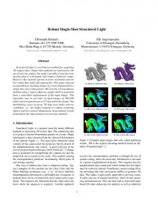
Figure 6 shows a snapshot of a 3D scan taken from two opposite modules at the same time. Two consecutive illuminations are used: the masked stripe pattern for 3D mesh reconstruction and a homogeneous white pattern to acquire the object texture. The problem of selfocclusion, which possibly leads to mislabeled stripes, is addresses in [8]. A combination of geometric coding, color coding and tracking over time aims to to solve the correspondence problem. The position and orientation of each module relative to a common world coordinate system (WCS) is known from system calibration. Therefore each module computes a 3D mesh relative to the WCS, which simplifies the model integration on the master computer. Even without
a closed mesh in figure 6, the person can be identified well and enough features can be extracted for motion capture applications. The scanning speed is highly dependent on the scene complexity, but frame rates of approximately 13Hz can currently be reached.
8 Conclusions and Future Work This work focuses on the simultaneous use of multiple one-shot structured light systems for high-speed scanning of human bodies under motion. We demonstrated that two nearly oppositely positioned modules can work in parallel and that pattern interference is avoided by adding a projection mask. This strategy also reduces the processing time by eliminating unnecessary parts of the background. The robustness, i.e. the recovery of the pattern on the scanned object, is increased by applying rapid polygonoffsetting combined with a simple tracking. The system consists of four Modules but currently only two of them are used. We started working on flexible switching mechanisms between pairs of scanning modules to increase the completeness of the integrated model.
Acknowledgments The authors gratefully acknowledge the support of Canon AG, Switzerland. The authors also gratefully acknowledge support by KULeuven GOA project ’MARVEL’ and SNF NCCR project ’IM2’.
References [1] O. Hall-Holt and S. Rusinkiewicz. Stripe boundary codes for real-time tructuredlight range scanning of moving objects. In Int. Conf. on Computer Vision, pages 359– 366, 2001. [2] S. Rusinkiewicz, O. Hall-Holt, and M. Levoy. Real-Time 3D Model Acquisition. In Proc. of Siggraph, 2002. [3] M. Proesmans, L. Van Gool, and A. Oosterlinck. Active acquisition of 3d shape for moving objects. In Int. Conf. on Image Processing, pages 647–650, 1996.
[4] M. Maruyama and S. Abe. Range sensing by projecting multiple slits with random cuts. IEEE Trans. Pattern Anal. Mach. Intell., 15(6):647–651, 1993. [5] M. Proesmans and L. Van Gool. One-shot active 3D image capture. In Proc. SPIE, volume 3023, pages 50–61, 1997. [6] T.P. Koninckx and L. Van Gool. Efficient, active 3D acquisition, based on patternspecific snake. In Proceedings 24th DAGM symposium on pattern recognition, pages 557–565, September 2002. [7] T. Koninckx, A. Griesser, and L. Van Gool. Real-time range scanning of deformable surfaces by adaptively coded structured light. In S. Kawada, editor, 4. intern. conf. on 3-d dig. imaging and modeling, pages 293–302, October 2003. [8] T. Koninckx, I. Geys, T. Jaeggli, and L. Van Gool. A graph cut based adaptive structured light approach for realtime range acquisition. In Proceedings of the 2nd International Symposium 3D Data Processing, Visualization, and Transmission, Thessaloniki, Greece, 2004. [9] J. Allard, V. Gouranton, G. Lamarque, E. Melin, and B. Raffin. Softgenlock: Active stereo and genlock for pc cluster. In Proceedings of the Joint IPT/EGVE’03 Workshop, Zurich, Switzerland, May 2003. [10] Kenneth E. Hoff, III, John Keyser, Ming Lin, Dinesh Manocha, and Tim Culver. Fast computation of generalized voronoi diagrams using graphics hardware. In Proc. of the 26th conf. on comp. graph. and interactive techniques, pages 277– 286, 1999.