A High-Throughput FPGA Architecture for Parallel Connected Components Analysis Based on Label Reuse Michael J. Klaiber∗ , Donald G. Bailey† , Silvia Ahmed∗ , Yousef Baroud∗ , Sven Simon∗ ∗ Institute
for Parallel and Distributed Systems, University of Stuttgart Email:
[email protected] † School of Engineering and Advanced Technology, Massey University, Palmerston North Email:
[email protected]
Abstract—A memory efficient architecture for single-pass connected components analysis suited for high throughput embedded image processing systems is proposed which achieves a high throughput by partitioning the image into several vertical slices processed in parallel. The low latency of the architecture allows reuse of labels associated with the image objects. This reduces the amount of memory by a factor of more than 5 compared to previous work. This is significant, since memory is a critical resource in embedded image processing on FPGAs.
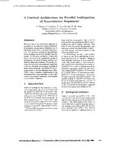
I. I NTRODUCTION Connected component analysis (CCA) is a major step in many image processing systems. It has the task of detecting pixels forming an image component in a binary image and extracting its feature vector (FV). The class of single-pass CCA algorithms has the major advantage of being able to process the image without the need of storing intermediate labels [1]. Single pass algorithms extract features such as the size, area, etc. of image components without storing the complete image in a memory. Most modern CCA algorithms apply the union-find algorithm which has been studied and evaluated extensively [2], [3]; union-find is also a foundation for the proposed algorithm. The recent need for systems capable of processing streamed high resolution images with high frame rates requires processing several pixels in parallel to achieve the desired throughput. One solution is to use dedicated hardware architectures for CCA realized on FPGAs. Several hardware architectures for CCA can process one pixel per clock cycle [1], [4]. Their throughput is limited by the maximum clock frequency on the FPGA. Higher throughput can be achieved through: run-length coding the image stream [5], [6]; parallel processing of pixels from different image rows [7]; or processing images in parallel using slice processing [8], [9]. These techniques increase memory requirements and require additional processing at the end of each frame, adversely affecting latency. In Figure 1 the proposed FPGA architecture for parallel CCA is depicted. It is based on [9] and gains a high-throughput by partitioning the image into several vertical image slices which are processed in parallel. Using the architecture from
Pixel Stream
Image Distribution Unit
...
Slice Processing Unit
Slice Processing Unit
Feature Vectors Feature Vectors
Fig. 1.
Feature Vectors
Coalescing Unit
Overview of a hardware architecture for parallel CCA.
[4] each slice processing unit processes one pixel per clock cycle with low memory cost and low latency. However, unlike [9], where components spanning multiple slices are merged at the end of the image, this paper describes how such segments can be merged on the fly, significantly reducing memory requirements and improving the latency. In the following section, a new algorithm for parallel CCA is described. The high-throughput hardware architecture is presented in Section III, followed by an analysis of the algorithm and architecture and the presentation of the experimental results in Section IV. II. A LGORITHM FOR PARALLEL CCA The image is divided into several vertical slices, with each slice processed in parallel by separate pixel processing instances. Each image slice is treated as a separate image, while a coalescing unit collects information on the relationship between components spanning multiple slices. If an image segment does not touch one of the slice borders, it is a local image component, and processing is complete when its end is detected. Whenever an image segment touches one of the slice borders, that connected component may span multiple slices. In this case it is necessary to merge the feature vectors associated with the adjacent segments. The relationship between the local segments and global components are represented in a global segment graph (GSG). In the GSG each global image component, each global image segment and each local image segment is represented by a vertex pointing either to a parent
Slice 1
Slice 2
ISM_LL L11
L21
L12
L22
ISM_GL L13
P1 G2
ISM_GG
P2
G1 G2
P3 P4 L23 SM
L14
P5 P6
Fig. 4.
Processing of the global mergers and finished segments Figure 2.
Fig. 2. Graph representation of a partitioned image consisting of several image segments.
I II III Fig. 3.
6 16
17
Input Pixel Stream
A
8
7 11
Neighbourhood Context
3
2
1
Data Table
12
18
B
13
Pixel contact types between neighbour slices.
vertex or to itself, indicating that it is the root. Figure 2 shows an example of an image partitioned into two image slices and its GSG. Since all of the image segments in slice 1 and slice 2 are part of a single image component, all of the local segments are part of a single global image component. Whenever a border object pixel is in the 8-neighbourhood of an object pixel in an adjacent slice, the two local image segments are connected by an inter slice merger (ISM). If an ISM happens for two segments which do not yet have a global label, a new global vertex is created to represent the segment. Both local segments are then linked to the new global segment. If one local segment already has a global label, the local segment without a global label is connected to the global vertex of the neighbouring segment. If both local segments already have global labels with different roots, it is necessary to merge these. The three types of ISM operations are called ISM LL, ISM GL and ISM GG. A fourth type of global merger occurs when two local segments within a slice with different global labels are merged. These belong to the same global segment; therefore a slice merger (SM) unifies their root vertices in the GSG. Figure 2 illustrates these four different merger types. ISMs can occur either horizontally or diagonally. In Figure 3.I all image slices are processed in raster scan order in parallel, and all reach the rightmost pixels at the same time. The local segments are therefore part of ISMs which are detected at the same time and signalled to the neighbour slices. For this reason the vertices of the local segments are only children of the global vertices involved in their ISMs. Global vertices of simultaneous ISMs belonging to the same global image segment have to be merged afterwards. Diagonal connections of the type shown in Figure 3.II are processed in exactly the same manner. For a type III diagonal merger, the local vertices are associated with global vertices during the ISM at the start of the row. The global vertices are then later connected via an SM. To keep track of when a global segment is finished, a child
D
Row Buffer
C
Link Table
Merger Table
Merger Control
Label Selection Finished FVs
Next Global Label
Global Mergers
Communication with CU
Fig. 5.
Stack Border Label Exchange with adjacent SPUs
Label Management
Recycled Labels
Architecture of slice processing unit (SPU).
counter (CC) is assigned to each global vertex to count the number of direct children vertices. The CC of a global vertex is updated on every global merger. When a local segment is finished, the CC of its parent’s vertex is decremented. If it reaches zero, the FV is transferred to its parent, and the global vertex is recycled. When the last local segment of a global component is finished, the CC of the root vertex becomes zero and the global segment is finished as well. This is illustrated in Figure 4 on the example image from Figure 2. III. H IGH - THROUGHPUT ARCHITECTURE FOR PARALLEL CONNECTED COMPONENTS ANALYSIS
The hardware architecture to realize this algorithm based on [9] is shown in Figure 1. The slice processing units are adapted from the architecture of [4] with modifications to label management to detect and facilitate global mergers. The major advantage over [9] is that global segments are coalesced on the fly. When an image segment spanning several slices is finished, all feature vectors of the individual segments it consists of, are already merged. Therefore, all the memory required for storing the information on the image segments can be reused. This significantly reduces the memory resources required and reduces processing latency. Therefore, the performance can be increased significantly for the same FPGA resources compared to [4] and [9]. Individual entities of Figure 2 are described in more detail in the following paragraphs. A. Slice Processing Unit The architecture of the slice processing unit is depicted in Figure 5. To represent the global and local vertices and their properties, the label selection needs local labels representing local segments and global labels representing global components. As in [4], the merger table keeps track of mergers among local segments. A link table is added, which stores the
...
connection from a local label to any associated global label. The feature vectors associated with the local image segments are stored in the data table. Since the link table requires local labels to remain unchanged until a local segment is completed, the aggressive relabeling scheme of [4] cannot be used. Instead, a new label management unit detects when a segment is completed and recycles labels that are no longer used. The label selection policy [1], to select the minimum label on mergers, no longer works because the labels are not sequential. To overcome this, the label is augmented with the row number it is generated in. Selecting the minimum augmented label gives the correct behaviour [1] when a merger occurs. The fact that every image pixel has both a global and a local label is also reflected in the label selection unit. The selection of the current pixel’s global label depends on the global labels of the pixel neighbourhood. If no global label is present, the current pixel’s global label is set to zero. If one is in the neighbourhood, it is copied to the current pixel. The presence of two different global labels requires a global merger (ISM GG or SM). The merger type and involved labels are pushed to the merger queue for the coalescing unit to process. The SPU’s link table is updated to the minimum global label. A valid flag is added to each data table entry to allow entries to be invalidated e.g. after two segments are merged or after readout. An active tag is also added to determine whether an image segment is finished. Whenever new data is written to the data table, this tag is updated to indicate that the entry was updated in the current row. By changing the tag at the end of each row, entries not updated during the current row can be detected. These finished image segments are read out while processing the next row by checking the active tag and valid flag of all data table entries in order. After readout, the data table entry can be reused by recycling the label to the label management unit. Implementing the data table using Block RAMs available on state-of-the-art FPGAs requires one port for table update [1]. The second port can be used to read out and invalidate feature vectors of finished image segments. B. Coalescing unit The coalescing unit (CU) has the task of establishing the relationship between local segments identified by the individual SPUs, and detecting the end of the resulting global segments. The architecture of the CU is depicted in Figure 6. The information collected on the global mergers and the FVs of finished segments are enqueued in FIFOs when entering the CU. The global merger table (GMT) stores the edges between global vertices of the GSG. Additionally, the find operation and path compression [10] are integrated into the GMT. The FVs of the global image segments, together with the associated child counters, are stored in the global data table (GDT). Each global label represents one entry in each of the GMT and GDT. The global label management unit (GLM) is responsible for providing global labels to the SPUs instantaneously. For each connected SPU the GLM has one
Global Merger Queues
...
FV Queues
...
Global Label Management
Coalescing Control Global Merger Table
Fig. 6.
Global Data Table
Finished Global FVs
Architecture of the coalescing unit.
counter for providing global labels and one queue for storing recycled global labels. The coalescing control unit coordinates the communication between the different sub-entities, which includes processing of global mergers and detection of finished global image segments. Mergers are processed sequentially due to the limited number of memory ports of the GDT and GMT, and their data dependencies. At the end of a global component, which is recognized by a child counter going to zero, its FV is output, so the global label can be recycled. IV. E XPERIMENTAL RESULTS AND DISCUSSION To analyse the performance and to determine whether realtime requirements can be met, it is crucial to determine the maximum number of mergers which can occur in the worst case. The CU performs 3 different types of operations: inter slice mergers (ISMs), slice mergers (SMs) and finished local image segments (FO). The number of cycles for performing the maximum possible merger operations, depends on the image width Wimage and the number of parallel slices p. W Each slice has a width of Wslice = image . ISM LL is the p only merger type which can generate global labels, SM and ISM GG have the ability to merge global labels and FO has the ability to invalidate global labels. Since a global merger operation needs different global labels, at most Wslice global 2 mergers can be carried out in one row of an image slice. For this to happen, at least Wslice global labels must exist. 2 Therefore these labels must have been generated by ISM LL operations in the rows before and not yet been merged to other global labels. This scenario can only occur every Wslice image rows, because at least Wslice ISM LLs are necessary 2 to generate the required number of global labels. Real-time processing requires that the maximum number of merger operations can be processed successfully within the number of clock cycles available. The large tree structure in the global merger table, which changes with every merger and every finished image segment makes an analytical exploration of the worst case difficult and beyond the scope of this work. Worst case images, as described above, were generated and simulated with the CCA hardware architecture to determine the maximum number of SPUs that the coalescing unit can keep up with. Table I shows the maximum number of slices pmax which can be processed by the coalescing unit for images of different width.
500
Image width
slices pmax
REGs
LUTs
BRAMs
fmax [MHz]
Max T [ GP ixels ] s
1024 2048 3072 4096 8192
10 16 19 21 32
10k 17k 22k 25k 39k
25k 42k 59k 70k 106k
42 74 90 99 153
136.4 137.9 137.3 132.6 125.8
1.1 1.7 2.0 2.2 3.2
Number of BRAMs
TABLE I R ESOURCE REQUIREMENTS FOR PARALLEL CCA ARCHITECTURE TARGET D EVICE : X ILINX V IRTEX 6 XC6VLX240T SPEEDGRADE -2
300 200 100
Required FPGA Resources[%]
0
3072x2048 4096x3072 8192x6144 Registers LUTs BRAMs
75
50
0 5
10
15
20
25
30
Number of image slices Fig. 7.
Diagram of FPGA resource requirements for different image sizes.
The resources required to extract the bounding box of each connected component are shown in Table I for different image sizes. Figure 7 shows that the number of Registers, LUTs and BRAMs grow almost linearly with the number of image slices. In addition, the maximum frequency of the CCA architecture remains almost constant over the whole range of image sizes and slices. This provides good scalability with processing throughput. Stack processing within the SPUs introduces a 20% worst case overhead [1]. The maximum throughput therefore is T = fmax × p × 0.8. A comparison of the memory requirements for the architecture in [9] including CU and with one SPU per slice is shown in Figure 8. The memory used by the coalescing unit can be shrunk by a factor of 42. This has a huge impact on the complete architecture, so that the memory requirements for complete architecture can be reduced by a factor of more than 5. Table II compares the proposed architecture for connected component analysis to other hardware architectures. This shows that processing throughput is significantly higher than [1], [4], [6], [8]. Compared to [9] the achievable throughput is similar, while the proposed architecture significantly reduces required hardware resources. TABLE II C OMPARISON OF THROUGHPUT WITH OTHER ARCHITECTURES .
Bailey et al. [1] Ma et al.[4] Kumar et al.[8] Lin et al. [7] Klaiber et al. [9] Zhao et al. [6] This work
41
82 Number of slice
316
Fig. 8. Comparison to architecture using CU from [9] and one SPU per slice for image size of 2048x1024.
25
0
Architecture using [9] This work
400
Parallelism ixels [ Pcycle ]
fmax [MHz]
Technology
Max T [ GP ixels ] s
1 1 6 4 32 1 32
N/A 40.63 100 100 138.8 95.7 126.8
Spartan-II Virtex II Virtex 5 0.35 um Virtex 6 Virtex II Virtex 6
N/A 0.04 0.6 0.4 3.5 0.1 3.2
V. C ONCLUSION The proposed parallel connected components analysis (CCA) algorithm and architecture allow the extraction of properties of image objects with a high throughput at low FPGA resource requirements by introducing an on-the-fly coalescing principle, reducing memory requirements and processing latency significantly. The resources for the proposed coalescing unit could be reduced by a factor of up to 42 compared to a previous architecture. This reduces the memory requirements of the complete CCA architecture by a factor of more than 5 and enables the realized system to perform parallel connected component analysis at more than 3 GPixels per second. ACKNOWLEDGEMENTS The authors would like to thank the German Research Foundation (DFG) for the financial support for this work carried out within Si 586 7/1 belonging to DFG-SPP 1423. R EFERENCES [1] D. Bailey and C. Johnston, “Single pass connected components analysis,” in Proceedings of Image and Vision Computing New Zealand, Dec. 2007, pp. 282–287. [2] R. Tarjan and J. van Leeuwen, “Worst-case analysis of set union algorithms,” J. ACM, vol. Vol. 31 No. 2, pp. 245 – 281, 1984. [3] J. Hopcroft and J. Ullman, “Set merging algorithms,” SIAM Journal on Computing, vol. 2, no. 4, pp. 294–303, 1973. [4] N. Ma, D. Bailey, and C. Johnston, “Optimised single pass connected components analysis,” in International Conference on Field Programmable Technology. FPT 2008., Dec. 2008, pp. 185 –192. [5] J. Trein, A. T. Schwarzbacher, B. Hoppe, K. Noffz, and T. Trenschel, “Development of a FPGA based real-time blob analysis circuit,” in Irish Signals and Systems Conference, Sept. 2007, pp. 121–126. [6] F. Zhao, H. zhang Lu, and Z. yong Zhang, “Real-time single-pass connected components analysis algorithm,” EURASIP J. Image and Video Processing, vol. 2013, p. 21, 2013. [7] C.-Y. Lin, S.-Y. Li, and T.-H. Tsai, “A scalable parallel hardware architecture for connected component labeling,” in 17th IEEE International Conference on Image Processing, Sept. 2010, pp. 3753 –3756. [8] V. S. Kumar, K. Irick, A. A. Maashri, and V. Narayanan, “A scalable bandwidth-aware architecture for connected component labeling,” in VLSI 2010 Annual Symposium, ser. Lecture Notes in Electrical Engineering, 2011, vol. 105, pp. 133–149. [9] M. Klaiber, L. Rockstroh, Z. Wang, Y. Baroud, and S. Simon, “A memory-efficient parallel single pass architecture for connected component labeling of streamed images,” in 2012 International Conference on Field-Programmable Technology. FPT, Dec. 2012, pp. 159 –165. [10] R. Seidel and M. Sharir, “Top-down analysis of path compression,” SIAM J. Comput., vol. 34, no. 3, pp. 515–525, Mar. 2005.