David Fick, Andrew DeOrio, Gregory Chen, Valeria Bertacco, Dennis Sylvester and David .... run basic routing step will often be reused by run rule check.
A Highly Resilient Routing Algorithm for Fault-Tolerant NoCs David Fick, Andrew DeOrio, Gregory Chen, Valeria Bertacco, Dennis Sylvester and David Blaauw Department of Electrical Engineering and Computer Science University of Michigan, Ann Arbor, MI 48109 {dfick, awdeorio, grgkchen, valeria, dmcs, blaauw}@umich.edu ABSTRACT Current trends in technology scaling foreshadow worsening transistor reliability as well as greater numbers of transistors in each system. The combination of these factors will soon make long-term product reliability extremely difficult in complex modern systems such as systems on a chip (SoC) and chip multiprocessor (CMP) designs, where even a single device failure can cause fatal system errors. Resiliency to device failure will be a necessary condition at future technology nodes. In this work, we present a network-onchip (NoC) routing algorithm to boost the robustness in interconnect networks, by reconfiguring them to avoid faulty components while maintaining connectivity and correct operation. This distributed algorithm can be implemented in hardware with less than 300 gates per network router. Experimental results over a broad range of 2D-mesh and 2D-torus networks demonstrate 99.99% reliability on average when 10% of the interconnect links have failed.
1.
INTRODUCTION
As the semiconductor industry moves further into the nanometer regime, two salient problems arise: efficiently connecting the increasing number of on-chip resources and effectively managing decreasing transistor reliability. Current methods of connecting onchip resources, such as buses and crossbars, may soon be precluded by the delay of long wires and the large number of elements that must communicate with each other. Networks on Chip (NoC) help mitigate this problem by decentralizing and distributing communication across the chip using a lightweight networking protocol, resulting in a high throughput, scalable solution. NoCs use a shared interconnect system to transmit packets of information between intellectual property components (IP, e.g., processor cores, caches, ASICs, etc.) through a distributed system of routers connected by links. Data sent through the network is converted into a packet, a formatted block of data, by a network adapter. Each packet is then labeled and divided into a sequence of uniformly sized flow units (flits) and sent from the adapter to a router [2], from where it travels from router to router through the network. While the NoC approach has been increasing in popularity with commercial chips such as Tile64 [1] and Polaris [19], it is threatened by the decreasing reliability of aggressively scaled transistors. Transistors are approaching the fundamental limits of scaling, with gate widths nearing the molecular scale, resulting in break down and wear out in end products [10]. Permanent faults due to device wearout are caused by mechanisms such as negative bias temperature instability (NBTI), oxide breakdown, and electromigration. These device level failures have architecture level ramifications, as a single faulty link or router will cause an entire NoC to fail, halting all traffic. Future processor technology generations will require significant error tolerance to many simultaneous faults. On-chip networks provide excellent opportunities for building a reliable system, as they provide redundant paths between IPs [18]. As the “glue” that holds a chip together, a NoC should be highly resilient to hardware failures and able to work around faulty routers
and links. In contrast, a faulty IP with even little or no protection can be disabled and isolated by the network, thus promoting NoC as a reliable system platform. A disabled IP would not hinder network performance, as the associated router can still be used. An ideal network should be able to diagnose where faults are in its own components and then reconfigure to mitigate those faults, maintaining full connectivity when possible. To avoid single points of failure, the reconfiguration process should be distributed and performed within the network itself.
1.1 Contribution of This Work We present a distributed routing algorithm for networks on chip, allowing a network to reconfigure around faulty components. Our solution’s novelty lies in its ability to overcome large numbers of faults in a fine-grained fault model without using virtual channels or adaptive routing, and in a distributed nature, which avoids single points of failure. Given only local information, the algorithm runs in lockstep at each network router to collectively reconfigure the network’s routing tables. Using a hardware implementation is more reliable as it may be unknown what IPs are safe for routing computation, and a software implementation would still require some degree of hardware support. The algorithm is implemented with less than 300 gates at each router, thus making it a low-overhead approach for both simple designs (even those without virtual channels) as well as complex ones. We found that networks routed using this algorithm are 99.99% reliable when 10% of the interconnect links have failed.
2. RELATED WORK Our work adopts the turn model originally proposed by Glass and Ni for adaptively routed networks in [6], which prevents network deadlock by disallowing various network turns. Later, in [7], they showed how the technique can be applied to n-mesh networks to tolerate (n-1) router failures (1 router failure for 2D-mesh). Their strategy uses no virtual channels but requires adaptive routing, whereas our work requires neither. Additionally we are not limited to any particular number of failures. Jie Wu uses the odd-even turn model to address convex, disjoint fault regions that do not lie on the mesh boundary [20]. Although his technique does not require virtual channels, the faultrequirements are strict. The work we present has no requirements on the fault patterns. A series of other works present solutions to adaptively route around router fault regions while enduring various restrictions and requirements [3, 4, 5, 11, 13, 14, 16, 17, 21, 22]. Packets are routed normally until encountering a fault region, and are then transmitted along the edge of that region. Initially, only rectangular, disconnected, non boundary regions could be tolerated while requiring a large number of virtual channels. Sometimes fully functional routers had to be disabled to meet the shape requirements. Recent work extends these techniques to router failures of arbitrary patterns using as few as two virtual channels. These additional virtual channels do not add to the performance of the system, however, as they are reserved for fault tolerance. Our work requires no vir-
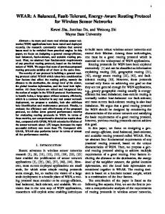
Figure 1: NoC router. When a packet enters the router, its header is decoded and the destination is looked up in the routing table. The packet is then transmitted in the direction specified in the routing table. Our algorithm rewrites this table when faults appear in the network. tual channels reserved for fault tolerance, so any virtual channels added to the system add to performance. Moreover, our work allows link-level failures and does not require adaptive routing, nor do we disable functional routers. Ho and Stockmeyer present a strategy that disables the IPs connected to a few sacrificial lamb routers, which helps prevent deadlock [9]. They demonstrate high reliability for a small number of faulty routers (3%), which is suitable for their application in the Blue Gene supercomputer. Our work targets reliability at higher failure rates while not disabling resources. Other approaches use additional virtual channels combined with adaptive routing to provide fault tolerance. Pruente et al. [12] present a technique that tolerates link-level failures using a relatively complicated algorithm and two virtual channels (one reserved for fault tolerance), while Gomez et al. [8] are able to tolerate up to five link failures with the addition of one virtual channel. In contrast with previous work, our solution requires no virtual channels, no adaptive routing, no particular fault restrictions, and no disabled routers. Many these works provide 100% reliability when conditions are met - while our technique can not guarantee that, experimental results show over 99.99% reliability when up to 10% of interconnect links have failed. Moreover, we provide hardware implementation results proving the feasibility of our approach.
3.
ROUTING ALGORITHM OVERVIEW
The routing algorithm presented in this paper reconfigures network routing tables in an offline process. It consists of a basic routing step and a number of rule checking steps. The rules constrain the basic routing step depending on the network topology and existing faults in order to safely redirect traffic around failed network resources, while the checks determine which rules to use. The algorithm is specifically designed for deterministically routed on-chip networks in SoC and CMP applications. Each router in our network contains a routing table (Figure 1), which lists an output port for each destination in the network. Packets traversing the network have a header flit with a destination ID field that is used to look up what direction to go at each router. Virtual channels are not required, but could be used to provide additional performance. The algorithm is implemented as a small hardware module in each router that runs in a distributed lock-step fashion. We model faults as link-level hard failures, thus each bidirectional link can be individually bypassed, allowing routers to be only partially functional. An entirely non-functional router is rep-
1: function main () { 2: foreach (rule) { 2: foreach (router) { 3: run_rule_check(rule, router) 4: } 5: } 6: foreach (dest) { 7: run_basic_routing_step(rules, dest) 8: } 9: } 10: 11: function run_basic_routing_step (rules, dest) { 12: if (dest == self) { 13: write_entry(‘‘local’’) 14: } else { 15: write_entry(‘‘invalid’’) 16: } 17: for num_router cycles { 18: if entry != ‘‘invalid’’ { 19: transmit_flags(rules) 20: } else { 21: check_for_flags(rules) 22: write_entry(priority_flag) 23: } 24: }
Figure 2: Pseudocode for rerouting algorithm. The function run basic routing step will often be reused by run rule check. resented by marking all four of its links as faulty. No restriction on the number or location of faulty links is assumed, but the routers must know which of their adjacent links are faulty. Each router works with its neighbors to collectively reconfigure their routing tables based only on this information. In addition, it is assumed that the routers know when they need to invoke the algorithm and how to resume operation after reconfiguration finishes. Failure detection and diagnosis, computation checkpointing, etc., are topics that have been extensively explored in other work [15] and are not discussed in this paper. The algorithm is comprised of multiple iterations of a basic routing step – a procedure that updates an entry in all routing tables for a particular destination. In the remainder of this section we describe the basic routing step as well rules to constrain it. We later show how to use these rules for specific topologies, 2D-mesh and 2D-torus, in Sections 4 and 5 respectively.
3.1 Basic Routing Step The basic routing step is shown in the second half of Figure 2. Each router selects the best direction to route a given destination based on information provided by its neighbors, then updates the corresponding entry in its routing table. Routers communicate through flags – one-bit signals transmitted to adjacent routers. At any point during the execution of the algorithm, entries in a routing table are marked either valid, if the corresponding destination is known to be reachable, or invalid otherwise. In the valid case the entry also contains the direction that packets must take to reach that destination. To determine the best path to the destination, all routers start by initializing the corresponding entry to invalid, except for the router connected to the destination locally. This router marks the entry as valid, and the proper direction in the table (Entry Initialization). All routers then repeat the following two steps until every router has had an opportunity to update its entry: 1. Flag transmission. During the flag transmission step, all routers whose destination entry is valid will send a flag to all of their adjacent routers. The other routers are silent.
Figure 3: Example of six iterations of the algorithm’s basic step. The only rule enforced disallows the Northeast corner turns, so the Southwest routers must go around the East side of the faulty link. “D” denotes the destination being routed, “!” denotes routers that wrote a valid entry that step, and “¬” denotes places where a turn rule prevented a flag from propagating. 2. Routing entry update. In this step, all routers who have (i) an invalid routing entry for the destination under analysis and (ii) have received a flag through any of their links in the previous step, update their entry to valid with the direction of the incoming flag. If a router has received a flag through multiple links, a priority selection procedure is used to select the preferred routing direction. If a router has not received any flag, or already has a valid entry, it does not take any action. Each panel of Figure 3 shows a single iteration of the basic routing step for a 3x3 mesh network. For an N router network, the routing steps above must be repeated N −1 times to cover the worst case scenario, where the routers are connected as a long chain. At the end of this process, if the router still has an invalid entry for the destination under analysis, then that destination is unreachable from that router.
3.2 Rules for the Basic Routing Step To avoid deadlock loops forming while performing the basic routing step, each router must also keep a set of rules – a list of disallowed links and turns. Links can be disallowed in the basic routing step by not transmitting flags across them, or by not accepting transmitted flags. Therefore a link can be disallowed by either router that it connects. Turns comprised of a path through two links connected by a router must be disallowed by their center router. The center router can disallow a turn between two links by not transmitting flags from one to the other, i.e., if its valid entry points to the second link, it will not transmit flags to the first link. These sets of rules are determined on a per-router basis depending on both the topology of the network and the present faults. In our subsequent examples of 2D-mesh and 2D-torus networks, we reuse the basic routing step to evaluate which rules are necessary to avoid deadlock. Each router will start with a set of default rules, removing or adjusting them based on the set of faulty links.
4.
2D-MESH ROUTING
2D-mesh is a common network topology for large scale chip multiprocessors due to its simple physical implementation. In this section we first discuss the natural loops that form in a mesh, and the rules required to prevent them. We then investigate situations when rules at individual routers need to be removed to maintain connectivity. Finally, we discuss a pathological case, as well as its solution. An example of mesh routing is provided in Figure 3.
Figure 4: Disallowing turns to avoid deadlock. Three examples are shown routing the same set of packets on the left, and the turns that they use on the right. Top row shows how the basic routing step will perform with no rules and no faults - no deadlock loops appear in the turn graph. The center row shows how routing the same packets results forms a deadlock loop when a fault is present. All packets take the only other available 2-hop route, and use overlapping resources which will eventually conflict with each other indefinitely. The third row shows how we disallow a turn to make one packet to take a longer path around the fault (green), which prevents a deadlock loop. “¬” denotes places where a turn rule prevented a flag from propagating.
4.1 2D-Mesh Rules A fault-free 2D-mesh network routed according to our algorithm will be deadlock-free without enforcement of any rules since S-EW-N priority leaves the Northwest and Northeast corners naturally unused (Figure 4, first row). However, a single fault in the network may cause a deadlock loop to form (Figure 4, second row). Deadlock occurs when a loop of utilized turns is formed. The basic routing step naturally uses minimal length paths, and every turn in the loop around the fault is the minimal length path between the two routers that it connects, thereby creating deadlock. Glass and Ni show that disallowing a pair of turns in an adaptive routing network prevents deadlock situations [6]. One turn must be disallowed for the clockwise direction, and another for the counterclockwise direction. In our experience, the best results were obtained when both the clockwise and counter-clockwise turns at the same corner were disallowed. An example of how disallowing a pair turns removes deadlock is shown in the bottom row of Figure 4. In our examples we choose to disallow the Northeast corner turns, which are North→East and East→North.
Figure 5: Selectively removing rules to allow full network connectivity. Strict adherence to the disallowed turn rule may result in a case where some routers are not able to reach the Northwest destination, although possible paths exist (left). This occurs because the routers on the western edge have the East→North turn disabled to avoid deadlock. Therefore, we remove the turn rule at the West router, restoring network connectivity (right). “D” denotes the destination being routed and “/” denotes routers unable to reach the destination.
4.2 Selectively Removing 2D-Mesh Rules Strict adherence to disallowed the turn rule may produce an inconsistent network, where consistency means that if one router can reach another then a return path also exists. In Figure 5, a single faulty horizontal link on the North edge of the network prevents six of the routers from obtaining a valid path to the Northwest router. All of the routers on the West edge of the network can reach this router by directing traffic to the North, however, since the East→North turn is disallowed, these fringe routers never transmit a flag to the East, cutting off the rest of the routers. In order to prevent this scenario we must identify routers where the turn rules should be removed to maintain a consistent network. To do this, we must check each corner by trying route from one end of the corner to the other using the basic routing step. If this cannot be successfully accomplished with the disallowed turn, then the corner turns must be allowed to maintain network consistency and both turns for the corner are then allowed. The center router knows if the corner was successfully routed based on the flags that it receives from the two other routers. We check one corner router at a time, so the minimal number of rules are removed in sequence. If this were not done then both fringe routers would have their turns allowed and the second faulty link in the example would cause a deadlock.
4.3 Pathological Case A pathological case infrequently arises in large networks with many faults. As shown in Figure 6, deadlock loops can form when two subnetworks are connected by a router with the turn rule removed. Effectively, the deadlock loop passes through the connecting router twice, as if folded over a point. We reduce this problem by using a routing priority that disfavors a different corner - in our example we use S-E-W-N priority to disfavor the Northwest corner. The pathological case can still appear if there is a single fault inside of each of the subnetworks, since the Northwest turns will still be used in that case, similar to the second row of Figure 4. We address this by formally disallowing a different corner for one of the subnetworks. Once we have changed which corner is being disallowed for this part of the network via a directed broadcast, we must check each of these new rules. The pattern can also repeat inside one side for a large network, so we allow the turn to be changed back to the original turn when new rules need to be removed. This part of the algorithm can loop by changing between these two corners as long as it needs. Any router that does not have its corner rule modified becomes “fixed”, and
Figure 6: Pathological case for large networks with many faults. The corner rule for the Southwest router was removed as desired, but a deadlock loop forms by passing through that router twice. We adjust the rules for one side to break the loop. is no longer changeable so that forward progress is made. In our implementation we switch between the Northeast and Northwest corners, broadcasting the corner-change signal to the East/North and North/West respectively.
5. 2D-TORUS ROUTING Tori are very similar to meshes so we start with the same rules described in our 2D-mesh example. Unique challenges for the basic routing step (described in Section 3.1) are present, since a torus network automatically forms deadlock loops even in absence of faults.
5.1 2D-Torus Rules Torus networks form loops around the outside of the network by continuing in the same direction until reaching the same router again. We address these loops with the addition of link rules. We first disallow all wrap-around links along the top edge of the network, then disallow one horizontal link in each row of the network. The horizontal links prevent a loop from forming in the same row. The vertical link rules along the North edge prevent a zigzagging pattern from looping around the network, as well as loops that would form in the same column. We choose a staggered pattern for the horizontal links in order maintain the performance provided by the torus topology. Each of these new rules (vertical link and horizontal link) needs to be checked, as shown in the first part of Figure 2. Horizontal link rules can be checked first, and all in parallel. If there is a broken link in the same row as a horizontal link rule then it is not necessary to have the rule since the broken link provides the same benefits. We can accomplish this check with a horizontal broadcast, where knowledge of broken links propagates horizontally and lifts any horizontal link rules. Since this broadcast starts at the ends of each broken link it is guaranteed to reach every router in the row. Vertical link rules can be checked similarly to the corner rules. One side of the link maintains the rule - we route the other side of the link and check if this side ever has a valid entry. If it does not then the link is needed for consistency and the rule is discarded. The horizontal and vertical rules only need to be checked once, regardless of whether the corner rules are changed or not. They are put in place to create a network that can be successfully routed by manipulating the corner rules.
5.2
Corner Rule Consistency
The 2D-torus topology adds the possibility of corner evaluation being inconsistent. Each corner has two turns, so the corner could be evaluated by routing one turn or the other. Meshes are always consistent, i.e., routing either turn yields the same result (routable or unroutable). Tori can be inconsistent in some cases since paths
EXPERIMENTAL RESULTS
We evaluated our algorithm on a number of 2D mesh and torus network sizes, ranging from 4x4 to 12x12 (Table 1). These sizes are representative of current industrial designs such as Tile64 (8x8) [1] and Polaris (10x8) [19]. Using a cycle-accurate simulator written in C++, each router was modeled as a single cycle design with 16-flit input FIFOs. Stimulus was produced with a constrainedrandom traffic generator with each packets being 8 flits long. We modeled faults as link-level failures, which allowed for a high degree of flexibility, since routers can retain partial functionality when experiencing faulty sub-components. Table 1: Networks topologies and sizes used for evaluation. 2D-Mesh
4x4 8x8 12x12
24 links 112 links 264 links
2D-Torus
30 Links
42 Links 99.9
Broken
Broken
8x8
Torus
99.8
10%
Mesh
12x12
99.7
99.6
99.5 10
20
30
40
Links Broken (%)
Figure 7: Reliability with increasing faults. All topologies were found to be at least 99.99% reliable at the 10% point.
2D-Torus Optimization
The link rules imposed for tori disallows more turns than necessary since they in effect disallow two sets of turns, one set for each connected router. We can limit this rule to only one set by ignoring the rule when the destination is on either side of the link. If we cross a disallowed link to reach a destination then we must also ignore the turn rule for that router in order to maintain network consistency. This allows us to more efficiently use the 2D-torus topology without incurring deadlock or consistency problems.
6.
4x4
4x4 8x8 12x12
32 links 128 links 288 links
6.1 Reliability Analysis In our first study, we explore the relationship between the number of faulty links and the reliability of the network. We randomly inject a number of unique link faults into various network topologies. After injecting the faults and allowing the network to reconfigure, we inspect the resulting tables to verify that the following properties hold true: • No deadlock condition is present: no set of turns used in routing the network form a ring (see Figure 4). • Routing tables are consistent: if router A has a valid entry for router B, then A and B have the same set of valid entries. • No routers are unnecessarily cut off: if adjacent routers A and B are connected by a non-faulty link, then each have a valid entry for the other. We repeated the experiment one million times for each data point, obtaining the results shown in Figure 7. As shown in the chart, all
8x8 Torus Network 60
50
18 Links
0 Links
Broken
Broken
(14.1%)
Latency (Cycles)
5.3
100.0
Reliability (%)
around the outside of the network may be blocked off when routing one turn versus another. This often happens when one of the routers connected by the turn is reachable only through the center router. When the other connected router is the destination, the first router is not able to reach it since the center router always routes directly to the destination, which blocks off all possibilities for the first router. When the first router is the destination, however, the second router may find a path around the outside of the network, which is an option that would not be available in a 2D-mesh network. Removing this turn rule would allow a deadlock path in the network, but not allowing it would create an inconsistent network. We resolve this by applying a fix-up to this turn in the form of a new link rule. Whichever connected router could not find the other is cut off by the center router, therefore disallowing the link to the other router will not cut off any part of the network. This forces both connected routers to take the path around the outside of the network to reach the other, and keeps the network consistent while not allowing deadlock. Since this rule is only added when it is needed, it doesn’t need a rule check.
40
30
20
10 0.0
0.1
0.2
0.3
Traffic Density
Figure 8: Packet latency for a given traffic density and number of faults. The highlighted region shows the range of 5th to 95th percentile, while the center line denotes the median. The network hits a latency wall at 0.30 and 0.15 traffic densities for 0 faults and 18 fault respectively. network configurations exhibit a reliability over 99.99% when a tenth of the links are faulty. Smaller 4x4 networks had 100% reliability for 2D-mesh, and 99.99999% reliability for 2D-torus, regardless of the number of faulty links. With larger networks however, the probability of a faulty network configuration increased as the number of faults increased beyond this point, although reliability in real implementations would be much higher, since errors tend to exhibit spatial locality (temperature, utilization, clock distribution, etc.).
6.2 Performance Evaluation In our second study, we investigated the effects of link failures on the performance of the network. Specifically, we measured the average latency of packets traversing the network as the density of randomly generated traffic increased. Density is shown as a per-
0.7
channel costs. At less than 300 gates per router, this approach is an efficient and effective addition to either simple or complex router designs. Experimental results showed an average reliability of over 99.99% when 10% of the network links have failed across a variety of networks sizes. Our routing algorithm enables the deployment of NoC architectures and systems where network connectivity and correctness must be maintained possibly at a performance cost, enabling graceful performance degradation as network resources fail.
Maximum Traffic Density
0.6
Torus
0.5
Mesh
0.4
8. ACKNOWLEDGMENT
0.3
4x4 0.2
9. REFERENCES
8x8
0.1
12x12 0.0 0
10
20
30
40
Links Broken (%)
Figure 9: Network traffic saturation. The amount of traffic that a network can support before it reaches the latency wall for a given number of faults. The median traffic density is used for this calculation. centage of the total injection bandwidth of the system, which is fixed and proportional to the number of routers in the network. Figure 8 shows the result of this analysis for an 8x8 2D-torus network. For low traffic densities, the latency is kept under 20 cycles, however, as the density increases, network saturation occurs, resulting in a latency wall. With injected faults, the latency wall is reached at lower traffic densities, as indicated by the graph. In addition, random fault injection creates variation in the onset of network saturation, shown by the shaded region (5th to 95th percentile). In our next experiment we further investigate the relationship between the number of broken links and the location of the latency wall, analyzing multiple network configurations. Here, we vary the number of broken links and record the traffic density at which the latency wall (70-80 cycle latency) is encountered. Each data point represent 5000 tests of 50,000 packets. The results shown in Figure 9 demonstrate that with an increasing failure rate, network saturation occurs at progressively lower traffic densities. This can be attributed to fewer operational paths available for communication among network routers, as well as longer routes around failed network components.
6.3 Area Evaluation Finally, we evaluated the area impact of implementing our rerouting solution in hardware. We implemented the 2D-torus variant of the algorithm as a Verilog module, and synthesized it with Synopsys Design Compiler and a state-of-the-art 45nm library. The overhead of implementing the algorithm in a 4x4 network was less than 300 gates per router. For comparison, a 12x12 network requires an additional 30 gates, attributed to slightly larger state machine counters.
7.
This research was funded in part by the Gigascale Systems Research Center and the United States National Science Foundation.
CONCLUSIONS
In this work, we have presented a general fault tolerant routing algorithm targeting NoC designs implemented on unreliable silicon as foreseen for future technology nodes. We also discuss specific implementations of the algorithm for 2D-mesh and 2D-torus networks. Our solution routes around network failures by leveraging redundancy inherent in NoC topologies while not incurring virtual
[1] S. Bell et al. TILE64 processor: A 64-core SoC with mesh interconnect. Proc. ISSCC, 2008. [2] T. Bjerregaard and S. Mahadevan. A survey of research and practices of network-on-chip. ACM Computer Survey, 38(1), 2006. [3] S. Chalasani and R. V. Boppana. Fault-tolerant wormhole routing algorithms for mesh networks. IEEE Trans. on Computers, 44(7), 1995. [4] A. Chien and J. H. Kim. Planar-adaptive routing: Low-cost adaptive networks for multiprocessors. Proc. ISCA, 1992. [5] J. Duato. A theory of fault-tolerant routing in wormhole networks. IEEE Trans. on Parallel and Distributed Systems, 8(8), 1997. [6] C. J. Glass and L. M. Ni. The turn model for adaptive routing. ACM SIGARCH Computer Architecture News, 20(2), 1992. [7] C. J. Glass and L. M. Ni. Fault-tolerant wormhole routing in meshes without virtual channels. IEEE Trans. on Parallel and Distributed Systems, 7(6), 1996. [8] M. E. Gomez, J. Duato, J. Flich, P. Lopez, A. Robles, N. A. Nordbotten, O. Lysne, and T. Skeie. An efficient fault-tolerant routing methodology for meshes and tori. IEEE Computer Architecture Letters, 3(1), 2004. [9] C.-T. Ho and L. Stockmeyer. A new approach to fault-tolerant wormhole routing for mesh-connected parallel computers. IEEE Trans. on Computers, 53(4), 2004. [10] E. Karl, D. Blaauw, D. Sylvester, and T. Mudge. Reliability modeling and management in dynamic microprocessor-based systems. In Proc. DAC, 2006. [11] S.-P. Kim and T. Han. Fault-tolerant wormhole routing in mesh with overlapped solid fault regions. Parallel Computing, 23(13), 1997. [12] V. Puente, J. A. Gregorio, F. Vallejo, and R. Beivide. Immunet: A cheap and robust fault-tolerant packet routing mechanism. ACM SIGARCH Computer Architecture News, 32(2):198, 2004. [13] S. Rodrigo, J. Flich, J. Duato, and M. Hummel. Efficient unicast and multicast support for CMPs. 2008. [14] J.-D. Shih. A fault-tolerant wormhole routing scheme for torus networks with nonconvex faults. Proc. IPF, 88(6), 2003. [15] D. P. Siewiorek and R. S. Swarz. Reliable computer systems (3rd ed.): design and evaluation. 1998. [16] C.-C. Su and K. G. Shin. Adaptive fault-tolerant deadlock-free routing in meshes and hypercubes. IEEE Trans. on Computers, 45(6), 1996. [17] P.-H. Sui and S.-D. Wang. Fault-tolerant wormhole routing algorithm for mesh networks. IEEE Computers and Digital Techniques, Jan 2000. [18] D. Sylvester, D. Blaauw, and E. Karl. ElastIC: An Adaptive Self-Healing Architecture for Unpredictable Silicon. IEEE Design & Test, 2006. [19] S. R. Vangal et al. An 80-tile sub-100w teraflops processor in 65-nm cmos. IEEE Journal of Solid-State Circuits, 2008. [20] J. Wu. A fault-tolerant and deadlock-free routing protocol in 2d meshes based on odd-even turn model. IEEE Trans. on Computers, 52(9), 2003. [21] J. Zhou and F. Lau. Adaptive fault-tolerant wormhole routing in 2d meshes. Proc. IPDPS, 2001. [22] J. Zhou and F. C. M. Lau. Multi-phase minimal fault-tolerant wormhole routing in meshes. Parallel Computing, 30(3), 2004.