meticulous accounting of the vast story of public land surveying and registration.
...... Most patents or deeds to land were in “free and common socage,” which ...
A History of the Rectangular Survey System PDF Version U.S. DEPARTMENT OF THE INTERIOR BUREAU OF LAND MANAGEMENT
Pdf Version modified from scans by; NATIONALTECHNICAL INFORMATION SERVICE SPRINGFIELD, VA 22161
The United States of America, To
A LL to
whom thefe prefents fhall come, Greeting:
NOW YE, That for the confideration
K
of
Dollars, we have granted, and hereby do
d&-
7
t h e Lot n u m b e r e d d -
-
in the Townfhip,
in the Range
lumbered
dCd-
excepting
Ind refevving one third Part ofall Gold, Silver, Lead and Copper Mines within the Fame, for future Sale or DifpoRtion : To have t o
A5
-
IN W IT NE S S
WHEREOF,
Heirs and AfEgns for ever.
We, the Commiffioners o f t h e Board of' n e a f u r y
have, in conformity t o an Act of Congrefs ofthe Lid United States, of the
Twenty-firR day ofApril, in the Year of our Lord, one Thoufand Seven Hundred and Eighty-feven, hereunto Feet our Hands and affixcd the Seal of t h e Treafury,
this-
day of
Ad
in the Year of o u r Lord, One Thoufand Seven Hundred and
p
n
d of the Independence of the United States ufAmel;ca&
-
Pi3 92 1 5642 1
..
11
A HISTORY OF THE RECTANGULAR SURVEY SYSTEM
...
111
UNITED STATES DEPARTMENT OF THE INTERIOR James G. Watt, Secretary
BUREAU OF LAND MANAGEMENT Robert F. Burford, Director
Library of Congress Cataloging in Publication Data White, C. Albert, 1926A history of the rectangular survey system. Bibliography: p. Supt. of Docs. no.: I53.2:Su7/2 1. Surveying-Public lands-United StatesHistory. 2. Surveying-Law and legislationUnited States. I. Title. TA521 .W47 333’ ,00973 82-4510 AACR2
First printing 1983 Second printing 1991
For sale by Superintendent of Documents, U.S. Government Printing Office Washington, D.C. 20402
Stock Number 024-001 1-001 78-6
iv
IN REPLY REFER TO:
United States Department of the Interior BUREAU OF LAND MANAGEMENT WASHINGTON, D.C. 20240
January 1983
Dear Reader: With i t s beginning more t h a n two hundred y e a r s a g o , the United S t a t e s R e c t a n g u l a r Survey System i s t y p i c a l l y , and y e t somewhat u n i q u e l y , a record of t h e American f r o n t i e r s p i r i t blended w i t h t h e concept o f government f o r t h e people.
C. A l b e r t White, U.S. C a d a s t r a l Surveyor, p r e s e n t s i n t h i s document a m e t i c u l o u s a c c o u n t i n g of t h e v a s t s t o r y o f p u b l i c land s u r v e y i n g and registration. This c l a s s i c r e s e a r c h c o n t r i b u t i o n i s a d e t a i l e d r e f e r e n c e which w i l l undoubtedly b e w e l l u s e d by h i s t o r i a n s , land use s p e c i a l i s t s , s u r v e y o r s , and a t t o r n e y s f o r contemporary d e c i s ionmaking , unders tand i n g , and judgments. M r . White began h i s s u r v e y i n g career w i t h t h e General Land O f f i c e i n 1946. Subsequently, as b o t h a Bureau of Land Management (BLM) and a p r i v a t e s u r v e y o r , h e a p p l i e d h i s d i l i g e n t a b i l i t i e s t o a wide range o f a c t i v i t i e s i n c l u d i n g i n v e s t i g a t i o n o f t h e d u r a b i l i t y o f b e a r i n g trees, t r a i n i n g , i n s t r u m e n t a t i o n , and r e f i n e m e n t s as w e l l as performing hundreds of "Ground Pounding" land s u r v e y s . Al White r e p r e s e n t s t h e U.S. s u r v e y o r of t h e mid- century of 1 9 0 0 ' s - a b r i d g e and i n t e g r a t o r of t h e wisdom and e x p e r i e n c e of h i s p r e d e c e s s o r s t o t h e expanding uses of l a t e s t c o s t e f f e c t i v e technology i n c a d a s t r a l surveying.
Bernard W. H o s t r o k Surveyor General
V
ACKNOWLEDGEMENTS The assistance of many persons was necessary to complete this work, and it would be impossible to thank them all by listing them here. However, acknowledgement and thanks are expressed to the U.S. Forest Service, National Advanced Resource Technology Center for their support and efforts in preparing a preliminary edition; to Away With Words for their excellent efforts in typing and editing; the Branch of Survey and Mapping Development, Denver Service Center, Bureau of Land Management for preparing numerous drawings and illustrations and administering the production of this publication. Special thanks go to Jerry Edler and Herman Weiss of the Denver Service Center, Branch of Survey and Mapping Development. The Washington Office, Division of Cadastral Survey, Bureau of Land Management provided enthusiastic support, and this publication has been made possible through that staffs special advice and cooperation.
vi
INTRODUCTION When first assigned to do an outline of the history of the development of the public land surveys and the social and economic conditions leading to the first land ordinance, my approach was the “usual” one: show the “changes” in the Instructions to Deputy Surveyors and the Manuals of Surveying Instructions. I soon came upon nagging questions: Why were the original townships numbered north from the Ohio River? Why were the sections first called lots? Why was the scheme changed t o “sections?” How did the present system of numbering the sections come about? Why did the Act of February 11,1805, call for the intersection method of subdividing the “two-mile blocks” and extend later to the subdivision of sections? Why were lakes of “25 acres and upward” meandered? The reader should by now understand the perplexities which were not answered by either the Instructions or the Manuals. These developments did not happen by accident; they had to have reasons and roots. But how t o find the answers and were the answers even available? I turned to my good friend Tom Tillman for advice and assistance, which was immediately given. He told me of the existence of Microcopy No. 478, which contained the letters from the Surveyor General Northwest of the Ohio (sent) to the Secretary of the Treasury and the Commissioner of the General Land Office; and of Sherman’s book, Peters’ book, and many others. He generously loaned me his collection of papers, and eventually told me how to obtain the Annual Reports of the Commissioners. We also discussed the format: by subject, or as a chronology?Chronology won because in the development, everything is cause and effect. One subject depends upon the other and cannot be divorced into neat little categories. The book is thus written in order of occurrence, wherever practical. Occasionally, as in legal cases, the subject is carried from inception to conclusion, but those instances are rare. The book was started from January through April of 1976. I “retired” on April 30,1976, and did not return to the Bureau of Land Management until August 1977. When asked to instruct the history of rectangular surveying a t the Cadastral Surveying course (held in Arizona in 19801, I suggested that the book might be completed as a reference for the course. Permission was generously granted and I resumed work on the book. The National Archives loaned me Microcopy No. 27, which contains the letters sent to the Surveyors General, 17961901, as well as thousands of letters to Congressmen, surveyors and citizens. The Multnomah County Library, Portland, Oregon, most generously allowed me to borrow the Serial Sets, the volumes of Senate and House Documents, which contained the Annual Reports of the Secretary of the
Interior and Commissioner of the General Land Office. Various offices of the Bureau of Land Management supplied me with copies of requested plats and field notes. Mr. Richard Crawford of the National Archives in Washington, D.C., supplied me with vital copies of certain documents. All of these are herein combined into one. Innumerable miscellaneous textbooks, encyclopedias, publications by other authors, newspapers, library and historical society references, and articles printed by the American Congress on Surveying and Mapping were used as references in the preparation of this book. Reference was frequently made to the original field notes and plats of the public land surveys. The intended use of this book is not that of a novel but as a reference for rules and policies, as well as the laws on which they are based. A subject is kept alive until finally laid to rest such as subdivision of sections or the survey of dried-up lakes. When a final decision is made, the subject is usually dropped. Some arguments have never been resolved: the use of line trees in establishing one sixteenth corners, the use of witness corners in restoring a true corner point, and the restoration of State boundaries which mark the boundaries of public lands. If the problem has never been finally resolved, the answers will not be found in this book. The book will not give the reader answers, only the precedence of what has gone before and why. Mineral surveys are not included. After 1851,the copies of letters from the Commissioner to the Surveyors General were kept in separate volumes; that is, the letters t o the Surveyor General of Oregon were kept in the Oregon Book, to California in the California Book, and so on. Microcopy No. 27 contains only the letters t o the Surveyors General in the States of Minnesota, Iowa, Missouri, Arkansas and Louisiana, and the public land States lying east thereof plus the letters to Surveyors and other citizens in the same area. Letters and Instructions pertaining to Oklahoma and Kansas after 1875 are also on Microcopy No. 27. The many volumes of letters to Surveyors General west of Iowa have not been filmed and were therefore not available t o me in preparing this book. Those volumes would undoubtably furnish additional information, as would all the other records pertaining to the public land surveys now stored in the National Archives. But I had to stop somewhere and use what I had, filling in the blanks with other sources. The Appendix to this book includes the original Instructions to the Deputy Surveyors, circulars, important letters, and at least the pertinent parts of the Manuals of Surveying Instructions. It is hoped that this book will be of value to all Surveyors dealing with the public land survey system, not just government surveyors. May it be some value to you all. C. Albert White
vii
...
vlll
TABLE OF CONTENTS Page CHAPTER I
CHAPTER I1
POLITICAL AND ECONOMIC EVENTS LEADING TO THE PASSAGE OF THE FIRST LAND ORDINANCE . . . . . . . . . . . . . . . . . . . . . . . . . . . . . . . . . . . . . . . . . . . . . . . . . . . . . . . . . . . . . . . . . . . . . . . . . English Claims to America . . . . . . . . . . . . . . . . . . . . . . . . . . . . . . . . . . . . . . . . . . . . . . . . . . . . . . . . . . . . . . . . . . . Land Tenure Systems . . . . . . . . . . . . . . . . . . . . . . . . . . . . . . . . . . . . . . . . . . . . . . . . . . . . . . . . . . . . . . . . . . . . . . . . Types of Government . . . . . . . . . . . . . . . . . . . . . . . . . . . . . . . . . . . . . . . . . . . . . . . . . . . . . . . . . . . . . . . . . . . . . . . . Locating Claims . . . . . . . . . . . . . . . . . . . . . . . . . . . . . . . . . . . . . . . . . . . . . . . . . . . . . . . . . . . . . . . . . . . . . . . . . . . . . The Western Lands . . . . . . . . . . . . . . . . . . . . . . . . . . . . . . . . . . . . . . . . . . . . . . . . . . . . . . . . . . . . . . . . . . . . . . . . . . Events During and Following the Revolutionary War . . . . . . . . . . . . . . . . . . . . . . . . . . . . . . . . . . . . . . . . . . . Land Ordinance of 1785 . . . . . . . . . . . . . . . . . . . . . . . . . . . . . . . . . . . . . . . . . . . . . . . . . . . . . . . . . . . . . . . . . . . . . The Northwest Ordinance of 1787 . . . . . . . . . . . . . . . . . . . . . . . . . . . . . . . . . . . . . . . . . . . . . . . . . . . . . . . . . . . . . Summary . . . . . . . . . . . . . . . . . . . . . . . . . . . . . . . . . . . . . . . . . . . . . . . . . . . . . . . . . . . . . . . . . . . . . . . . . . . . . . . . . . .
1 2 5 8 9 9 10 11 15 16
DEVELOPMENT OF THE RECTANGULAR SYSTEM OF SURVEYS ......................... The Period 1785-1796 . . . . . . . . . . . . . . . . . . . . . . . . . . . . . . . . . . . . . . . . . . . . . . . . . . . . . . . . . . . . . . . . . . . . . . The Period 1796-1812 . . . . . . . . . . . . . . . . . . . . . . . . . . . . . . . . . . . . . . . . . . . . . . . . . . . . . . . . . . . . . . . . . . . . . . The Period 1812-1836 . . . . . . . . . . . . . . . . . . . . . . . . . . . . . . . . . . . . . . . . . . . . . . . . . . . . . . . . . . . . . . . . . . . . . . The Period 1836-1849 . . . . . . . . . . . . . . . . . . . . . . . . . . . . . . . . . . . . . . . . . . . . . . . . . . . . . . . . . . . . . . . . . . . . . .
17 18 29 59 96
CHAPTER I11
THE GENERAL LAND OFFICE WITHIN THE DEPARTMENT OF THE INTERIOR . . . . . . . . . .113 The Period 1849-1910 . . . . . . . . . . . . . . . . . . . . . . . . . . . . . . . . . . . . . . . . . . . . . . . . . . . . . . . . . . . . . . . . . . . . . 114
CHAPTER IV
THE DIRECT SYSTEM TO END OF THE GENERAL LAND OFFICE ........................ The Period 1910-1946 . . . . . . . . . . . . . . . . . . . . . . . . . . . . . . . . . . . . . . . . . . . . . . . . . . . . . . . . . . . . . . . . . . . . .
CHAPTER V
187 188
SURVEYORS GENERAL OF THE PUBLIC LANDS STATES . . . . . . . . . . . . . . . . . . . . . . . . . . . . . . . . . 193 Commissioners of the General Land Office . . . . . . . . . . . . . . . . . . . . . . . . . . . . . . . . . . . . . . . . . . . . . . . . . . . 194 Offices of Surveyors General by State . . . . . . . . . . . . . . . . . . . . . . . . . . . . . . . . . . . . . . . . . . . . . . . . . . . . . . .195-224
APPENDIX TABLE OF CONTENTS Page I . Letter and Instructions t o District Surveyors or Subdividing Sections, Jared Mansfield, August 20, 1804. . . . . . . . . . . . . . . . . . . . . . . . . . . . . . . . . . . . . . . . . . . . . . . . . . . . . . . . . . . . . . . . . . . . . . . . . . . . . .
II.
231
General Instructions t o Deputy Surveyors, Jared Mansfield, 1804 . . . . . . . . . . . . . . . . . . . . . . . . . . . . . . . . . .
237
III. Letter Instructions to Deputy Surveyors, Thomas Freeman, June 1811 . . . . . . . . . . . . . . . . . . . . . . . . . . . . .
239
IV . Letter; Josiah Meigs to Thomas Freeman, Surveyor General of Mississippi, March 13, 1815. . . . . . . . . .241
V.
Letter; Thomas Freeman to Josiah Meigs, April 29, 1815. . . . . . . . . . . . . . . . . . . . . . . . . . . . . . . . . . . . . . . . . . 241
VI .
Letter; Edward Tiffin to Josiah Meigs about Rector Instructions, July 26, 1815......................
242
VII .
Instructions for General (William) Rector, July 1815. . . . . . . . . . . . . . . . . . . . . . . . . . . . . . . . . . . . . . . . . . . . . .
243
VIII . Instructions for Deputy Surveyors, from Edward Tiffin, July 1815..................................
245
IX .
Letter; Thomas Freeman to Silas Dinsmore, September 15, 1819. . . . . . . . . . . . . . . . . . . . . . . . . . . . . . . . . . .
251
X . Letter; Edward Tiffin t o George Graham, September 22, 1823. . . . . . . . . . . . . . . . . . . . . . . . . . . . . . . . . . . . .
255
ix
XI . Letter; Instructions to Edward R . Downing from John Dinsmore, March 1830.......................
256
XI1. Letter of Instructions to Surveyors General, from Elijah Hayward, July 28, 1831....................
257
XI11. Letter; Elijah Hayward to Gideon Fitz, October 24, 1831. . . . . . . . . . . . . . . . . . . . . . . . . . . . . . . . . . . . . . . . . .
261
XIV . Instructions for Surveying in the State of Mississippi by Gideon Fitz, December 1831................ 263
xv . XVI .
Specimen Field Notes for State of Mississippi, by Gideon Fitz, May 1832...........................
275
Circular to Surveyors General. about lotting sections, from Elijah Hayward, May 8, 1832. . . . . . . . . . . .281
XVII . Instruction to Deputy Surveyors in Arkansas, 1833. . . . . . . . . . . . . . . . . . . . . . . . . . . . . . . . . . . . . . . . . . . . . . .
283
XVIII. General Instructions to Deputies for Ohio, Indiana and Michigan, 1833. ............................
291
XIX . General Instructions to Deputy Surveyors in Illinois and Missouri, 1834............................
301
xx .
Letter; Robert Lytle to Erastus Farnum, about subdividing sections, October 30, 1835. . . . . . . . . . . . . . .312
XXI .
General Instructions to Deputy Surveyors in Arkansas, 1837......................................
313
XXII .
General Instructions to Deputy Surveyors in Florida, 1842........................................
321
XXIII.
General Instructions to Deputy Surveyors in Arkansas, 1843. . . . . . . . . . . . . . . . . . . . . . . . . . . . . . . . . . . . . .
329
XXIV .
General Instructions to Deputy Surveyors in Wisconsin and Iowa, 1846............................
339
xxv .
Special Instructions to John Mullett from Lucius Lyon, April 22, 1848. ............................
356
XXVI . Special Instructions t o Guy Carleton from Lucius Lyon, July 14, 1849..............................
357
XXVII . General Instructions to Deputy Surveyors for Ohio, Indiana and Michigan, 1850....................
359
XXVIII . General Instructions to Deputy Surveyors in Florida, 1850. . . . . . . . . . . . . . . . . . . . . . . . . . . . . . . . . . . . . . . .
381
XXIX .
General Intructions to Deputy Surveyors in Wisconsin and Iowa, 1851.............................
385
xxx .
Instructions t o Deputy Surveyors in Illinois and Missouri, 1856....................................
401
XXXI . Manual of Surveying Instructions t o the Surveyor General of Oregon, 1851.........................
433
XXXII. Manual of Surveying Instructions, 1855. . . . . . . . . . . . . . . . . . . . . . . . . . . . . . . . . . . . . . . . . . . . . . . . . . . . . . . . . .
457
XXXIII . Instructions to Surveyors General. Amendments to 1855 Manual, June 1, 1864.....................
501
XXXIV . Circular; t o Surveyors General about Lot Numbering, July 28, 1866...............................
506
xxxv .
Circular No . 22 , about Island Surveys, June 10, 1868. . . . . . . . . . . . . . . . . . . . . . . . . . . . . . . . . . . . . . . . . . . . .
507
XXXVI . Circular; about Surveying Lake Beds, July 13, 1874. . . . . . . . . . . . . . . . . . . . . . . . . . . . . . . . . . . . . . . . . . . . . .
508
XXXVII . Circular; about Acceptance and Filing of Plats; April 17, 1879.....................................
509
XXXVIII.
Letter Circular; Subdivision of Sections and Restoring Lost Corners, November 1, 1879 . . . . . . . . . . . . . 509
XXXIX . Manual of Surveying Instructions, 1881. . . . . . . . . . . . . . . . . . . . . . . . . . . . . . . . . . . . . . . . . . . . . . . . . . . . . . . . . .
511
XL . Circular Booklet; Restoration of Lost and Obliterated Corners, March 13, 1883......................
545
XLI . Circular No . 119; Subdivision of Sections, June 2, 1887. . . . . . . . . . . . . . . . . . . . . . . . . . . . . . . . . . . . . . . . . . .
553
X
XLII . Manual of Surveying Instructions, 1890. . . . . . . . . . . . . . . . . . . . . . . . . . . . . . . . . . . . . . . . . . . . . . . . . . . . . . . . . .
555
XLIII.
Manual of Surveying Instructions, 1894. . . . . . . . . . . . . . . . . . . . . . . . . . . . . . . . . . . . . . . . . . . . . . . . . . . . . . . . . .
595
XLIV .
Circular; Restoration of Lost or Obliterated Corners and Subdivision of Sections. October 16, 1896. . . . . . . . . . . . . . . . . . . . . . . . . . . . . . . . . . . . . . . . . . . . . . . . . . . . . . . . . . . . . . . . . . . . . . . . . . . . .
683
XLV . Manual of Surveying Instructions, 1902. . . . . . . . . . . . . . . . . . . . . . . . . . . . . . . . . . . . . . . . . . . . . . . . . . . . . . . . . .
693
XLVI. XLVII .
Circular Booklet; Restoration of Lost or Obliterated Corners and Subdivision of Sections. June 1, 1909. . . . . . . . . . . . . . . . . . . . . . . . . . . . . . . . . . . . . . . . . . . . . . . . . . . . . . . . . . . . . . . . . . . . . . . . . . . . . . . . .
753
Letter of Instructions; Topography, August 15, 1910. . . . . . . . . . . . . . . . . . . . . . . . . . . . . . . . . . . . . . . . . . . . . .
765
xi
xii
CHAPTER I POLITICAL AND ECONOMIC EVENTS LEADING TO THE PASSAGE OF THE FIRST LAND ORDINANCE
ENGLISH CLAIMS TO AMERICA
latitude. Thus the foundation was laid for 200 years of land disputes regarding overlapping claims. Under these charters the land was not granted outright to the company. Both colonial government and land distribution were subject t o royal control. In 1609, the two charters were relinquished and new charters were granted. The Virginia Company was granted land extending from 200 miles south and 200 miles north of Old Point Comfort (400 miles of seacoast) "extending west and northwest to the south sea" (Pacific Ocean). It was on this charter that Virginia was eventually to claim Kentucky and the Northwest Territory. The Plymouth Company failed in its initial attempt at settlement and made no further efforts, so the charter was forfeited. In 1620, a charter was granted to the New England Council which covered the lands between 40° and 48° north latitude and from "sea to sea." Again the grants overlapped (see Fig. l),but were not considered important because what the King granted the King could also take away, within limits, and the lands could only be held by actual settlement. The boundaries were later changed, in part, by grants and charters to other colonies.
By 1550, the Spanish had explored most of the eastern coast of North America and the French had explored the Gulf of St. Lawrence. The French and Spanish claimed all these lands, basing the claims on the right of discovery and conquest. The English had made very few explorations in the New World and had very little knowledge of the land, geography, and native inhabitants. But when England broke her close religious and political ties with Spain in the late sixteenth century, she repudiated the Spanish claim that prior discovery established the full right of possession. England took the stand that occupancy and use was the final test of ownership. Although she knew that the continent was occupied and in use by the native Indians, the Indians were considered inferior; they were non-Christian savages with no rights in land tenure under English law and customs. It was on the basis of occupancy and use that England eventually took possession of the eastern coast of North America between 31° and 49° north latitude. The occupancy and use doctrine originally granted lands in the colonies and this has continued through the history of the United States to the present.
New England The 1620 charter gave the New England Council full power t o grant lands and issue patents. In 1622, the Council granted the territory that is now New Hampshire and Maine to John Mason and Ferdinand0 Gorges, who divided the lands in 1635; Mason's portion became New Hampshire. Gorges' grandson sold Maine t o John Usher, a Boston merchant, in 1677 for 1,250 pounds and Usher immediately deeded the land to Massachusetts. In 1629, the Massachusetts Bay Company was given a charter to all of the land between parallels of latitude three miles north of the Merrimac River and three miles south of the Charles River. This charter was annulled in 1684, and the second charter of the Massachusetts Bay Company was issued in 1691; it incorporated the Plymouth Colony on Cape Cod and Maine. The boundaries were well defined and describe the present Commonwealth of Massachusetts. But that state was later to claim western lands in what is now Pennsylvania, Michigan, Illinois, and Wisconsin on the basis of the 1629 charter. Maine remained a part of Massachusetts until 1820 (see Fig. 2). In 1662, the settled towns in Connecticut were consolidated and a charter granted to that colony, which was bounded on the east by Narragansett Bay, on the north by Massachusetts and on the south by the Atlantic Ocean, including all islands along the coast, and extending t o "the South Sea" (Pacific Ocean) to the west. It was on the basis of this grant that Connecticut was to claim and receive lands in what is now the State of Ohio (see Fig. 2). Rhode Island was settled by Roger Williams and his followers in 1636 without benefit of a charter or grant; Williams purchased the lands from the Indians and claimed it on that basis. The Rhode Island settlement and Providence Plantations were considered squatters by Massachusetts Bay. A charter was granted in 1663 for the lands which are now essentially marked by the present boundaries of Rhode Island, although it took nearly 100 years to settle the boundary
Colonization All title to land in England was from the King who could grant lands as he saw fit under any conditions he felt met his needs and desires and those of the grantee. The King or Queen was the sovereign, but due to wars with Spain and France, the English sovereign was not financially able to bear the high cost of establishing colonies in America. If colonization were to take place, it had to be accomplished with private capital. Generally, there were three classes of people in England who would participate in colonization: (1) T h e very rich merchants, traders and aristocrats. This group could furnish the capital expense and outlay if they could expect a good return on their investments. Few would ever actually make the trip to America themselves. (2) T h e middle-class. This group could finance the cost of ocean passage, provide themselves with tools, etc. But they needed a reasonable expectation of a better life and ability t o build an estate in the new land. (3) The verypoor tenants, unemployed, paupers and seruants. These people had little to lose and everything t o gain if they could migrate but had no means to do so. The solution t o colonization was the groups of wealthy people formed companies, bought stock in a company, and undertook the expense of sending the third class of people to America. In return, the Crown granted such a company a charter for lands in America, which was largely a high risk investment; it eventually led to large land-speculating companies which still exist in one form or another in the United States.
The Virginia Charters In 1606, the London Company was formed by a large group of investors. They were granted the right t o settle the land between 34° and 41" north latitude. The Plymouth Company was granted settlement rights between 38° and 45°north 2
sylvania. Several battles were fought over jurisdiction in that area and wasn’t settled until 1782.
disputes with Connecticut and Massachusetts. Rhode Island never had any claim to western lands. The present state of Vermont was claimed by both New Hampshire and New York, was never an individual colony, and, after settlement of boundary disputes, was admitted to the Union in 1791. All vacant lands within her boundaries became the property of the State.
Delaware The “Three Lower Counties” were first settled by the Swedes, taken over by the Dutch, granted to the Duke of York, and then sold t o William Penn in 1682. Penn granted a separate charter to the Delaware counties in 1701. The grant to Maryland (Lord Baltimore) for these same lands was ignored. Delaware had no claim to any western lands.
New York The Dutch settled and claimed the lands along the Delaware and Hudson Rivers based on the right of discovery and Henry Hudson’s explorations. They settled on Manhattan Island in 1624 and eventually granted lands including the large patroon estates along the Hudson. Sweden established settlements in the Delaware Bay area in 1638 and later. England claimed these same lands, and in 1664 granted the lands between the Connecticut and Delaware Rivers to the Duke of York. The Dutch and Swedes had granted lands to their citizens, and the English honored these “foreign” patents after evicting the foreign governments. This policy of honoring all bona fide patents or claims issued by previous governments was to continue throughout all of the later land acquisitions by the United States. The grant to the Duke of York included lands also granted to Connecticut, Massachusetts and New Hampshire, and many boundary disputes resulted. York’s claim to lands in what is now western New York were based on his jurisdiction over the Six (Indian) Nations. The territory which is now the State of New Jersey was deeded to George Carteret and John Berkeley by the Duke of York in 1664. They honored the previous settlers’ claims, set up a government, and sold lands. New Jersey had no western land claims.
The Carolinas In 1663, Charles I1 made a grant of the charter of Carolina to the Earl of Clarendon and seven other proprietors covering the lands between 31° and 36° north latitude. A second charter in 1665 covered the lands between 29° and 36“31‘ north latitude. Both charters extended from the Atlantic to Pacific Oceans. In 1729, the English government purchased the proprietors’ rights in North Carolina and divided the colony into two parts. The boundaries of North Carolina were described as being: “On the north, the south boundary of Virginia (about 36’30’ north latitude), and on the south, by 35’34’ north latitude and extending to the Pacific Ocean.” Presumably South Carolina contained the remainder; thus both North and South Carolina had claims under the charters to lands extending to the Pacific Ocean (see Fig. 3). Georgia Georgia was part of the Carolinas but was not being settled by those colonies. In 1732, King George I1 granted a charter to James Oglethorpe and a board of trustees for the lands between the Savannah and Altamaha Rivers and extending from the headwaters of those streams along parallels of latitude “to the South Seas.” In 1764, the boundaries were expanded southerly to St. Mary’s River (along the seacoast), up that stream t o its headwater, west to the confluence of the Flint and Chattahoochee Rivers, up the Chattahoochee to 31” north latitude, and then along that parallel to the Mississippi River. Thus Georgia laid claim to what is now most of the States of Alabama and Mississippi (see Fig. 3). An examination of Figs. 1 , 2 , and 3 reveals that all of the land east of the Mississippi River and north of 31” north latitude was claimed by one or more of the colonies under one charter or another at the beginning of the Revolutionary War. It was these claims and the lands involved that led to the need for the first land ordinance.
Maryland In 1632, Lord Baltimore was granted the territory south of 40° north latitude, south to a line drawn easterly to the Atlantic from Watkins Point in Virginia, and from the ocean to the headwaters of the Potomac River and lying north of that river. Lord Baltimore was later to lose a substantial part of this grant to what are now the States of Delaware and New Jersey. Since Maryland had no western lands, this reduction in area was to rankle Maryland through the Revolutionary War period and cause numerous boundary disputes. Pennsylvania In 1681, William Penn was granted the lands south of 43” north latitude (actually the 42nd parallel), extending west from the Delaware River 5° of longitude. The southern boundary was to be determined by a circle of 12 miles radius around New Castle in Delaware connecting with 40° north latitude, which was the north boundary of Maryland. New Castle was much too far south of 40° latitude, and this resulted in the famous boundary dispute between Penn and Lord Baltimore, which was settled by court decision and adjudication. The soutKern boundary of Pennsylvania is the Mason-Dixon Line, surveyed along a parallel of approximately 3V43’15‘’north latitude, which deprived Maryland of a rather large area along her northern border. Because of the definite western boundary, Pennsylvania could claim no western lands. But Penn’s grant included land claimed by Connecticut in the “Wyoming Valley” in northeastern Penn-
LAND TENURE SYSTEMS The colonial governments, proprietors and companies had several systems for disposing of land and methods by which legal title to the land was held. Many of these customs and restrictions came to be a source of irritation to most people with the result that most were abolished after the Revolutionary War.
Grants In the first instance, colonial land was granted to a settlement agency. The main “catch” was that in order to hold the land, settlers had to be placed on the land. The settlement agency could then grant the land to others under a wide variety of systems and acreages. Large grants were also made to individuals directly by the King. In some instances, 5
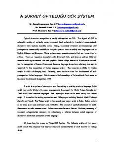
Figure 4. A New England Township (courtesy of New Hampshire Historical Society)
Technically, the same type of title passed in New England but quitrent was usually not collected or even required.
the grantee set up large manors or feudal-type estates. Shareholders in the settlement companies received large areas based on the number of shares they had purchased. Land grants were made t o support schools, colleges and churches.
Quitrent One big source of irritation to the small land owner was quitrents. When land was granted to the settler he was usually free of quitrent from 7 to 20 years. But once he was producing an income he had to pay a small quitrent, perhaps only a few pennies per acre, to the grantor. Regardless of how many times the land might be sold, it was subject to quitrent, in theory, forever. The small owners hated paying quitrent and frequently refused to do so. Since the collection of quitrent was difficult and costly, the original grantor or his heirs could do little to collect it. Quitrent was not a tax as such, but was more in the nature of a perpetual lien against the land.
Headrights In the southern colonies, each man was granted 50,100, or more acres as a headright. He was required to settle on the land, clear part of it, and make a farm. Under this system every settler soon began to believe that he was entitled to land, one way or another. The practice soon developed of granting a headright to each person, an additional headright to the person who may have paid for passage, another to the captain of the ship who carried him across the ocean, etc. Thus if a man in London paid the expenses of 50 people to settle, each of those 50 people received a headright and the benefactor received a like amount; large land holdings were acquired in this manner.
Primogeniture An old English practice of inheritance by the oldest son was brought to America; primogeniture means that the oldest son inherits the entire estate. He may have a moral obligation t o support his younger brothers and sisters but they could not inherit from him. This restriction in titles was distasteful to the younger children and the small land owners, but it was a means of keeping large estates and manors intact because the inheritance could not be sold and creditors could not foreclose.
Land Sales Direct land sales took place a t an early date in all of the colonies except New England. A man could request the right to purchase land and, if approved, would pay a stipulated price. Acreages ranged from 100 to 1,000 to perhaps 150,000 acres or more. The prices varied with location or quality but ranged from as little as three pence up to perhaps one pound per acre. Large land-speculating companies usually paid the least; however, selling land was not an established governmental policy.
Entails If land granted t o a man was entailed it meant that only his lineal descendants could own it thereafter. His heirs could not sell or transfer the land to someone else. If there were no heirs, the land reverted to the original grantor or his heirs; thus, the man and his heirs were not free to sell the estate.
New England Towns The New England colonies of Connecticut, Massachusetts, and Rhode Island were corporate colonies where the land was held and disposed of directly by a corporation. The people had close religious ties, the land was of comparatively poor quality, and the climate severe. A group of 30 or more men with families would join together and apply to the corporation for a land grant; if approved, they initially surveyed the “town.” The exterior boundaries were usually a rectangle of 6 to 10 miles square. The graup then divided the land among the members according to each man’s needs and issued title to the allotted-lands. Land couldn’t be sold without the group’s permission. These New England townships are said to be the origin of our present-day rectangular township system. The big advantage was that of common boundaries, with no “gaps” or “gores” of land left between ownerships; other advantages were survey before occupancy and near certainty of boundary locations. New York, New Hampshire, and other colonies sometimes used a modified rectangular township system for disposing of land to the colonists. Later many townships were surveyed in Maine, six miles square in cardinal directions, six miles square non-cardinal, and rectangularly shaped lying in various directions. Fig. 4 is a township in New Hamsphire surveyed in 1752 to 1753 and illustrates a typical layout.
TYPES OF GOVERNMENT Three different types of government existed in the colonies immediately prior to the Revolutionary War under which land was sold, granted, and surveyed. These types were royal, proprietary, and corporate colonies, all of which were subject to at least some restrictions by the King and Parliament of England.
Royal Colonies Prior t o the Revolution, New Hampshire, New York, New Jersey, Virginia, North and South Carolina and Georgia were Royal Colonies. The King appointed a governor who took the place of the King in local affairs and who appointed the council (similar to the Senate); the local citizenry elected a lower house or assembly. The assembly had the power to approve or levy taxes and approve the laws made by the governor and council. The governor depended on taxes for his support, so the colonial assembly had considerable control over the governor’s actions. Proprietary Colonies Delaware, Maryland and Pennsylvania were Proprietary Colonies. The proprietor took the place of the King, set up the system of government, and appointed the governor. Otherwise the system of local government was in the hands of the local assemblies, similar to the Royal Colonies.
Free and Common Socage Most patents or deeds to land were in “free and common socage,” which meant that the patentee held a fee title but the land was subject to certain restrictions, such as the requirements for settling, clearing and payment of quitrent.
Corporate Colonies Connecticut, Massachusetts and Rhode Island were gov8
erned by the corporation under their charters. Rhode Island and Connecticut retained these charters and governed under them until after the Revolution. Massachusetts was forced to accept a Royal governor. He governed under a general assembly and had full power to grant lands, issued patents and make laws. This action by the King was partially responsible for the dissension which led to war. Each of the colonies elected a colonial assembly, set up local and county governments, made laws, and had local courts, not dissimilar from what now exists in the United States, but they did not elect the governor and had no representatives except lobbyists in the English parliament.
and make his claim on the same land. This whole system led to many overlapping claims, boundary disputes, and clouded titles which the courts were swamped with. The New England town system of prior rectangular survey, careful marking and surveying the lots within the town, walking the bounds each year to preserve the boundary marks, and careful platting and recording was far superior to the indiscriminate location methods used in the other colonies. It also prevented the taking of only the good land, leaving the poorer land unused. The New England townships also provided for roads and highways, gave a definite lot to schools and churches, and had other advantages.
LOCATING CLAIMS
Squatters and Preemption It was supposed to be illegal for a man to occupy land without permission or by some type of grant, but the practice of squatting on the land, building a cabin and clearing ground for crops was widespread, especially west of the mountains in Kentucky and Tennessee. The Indians often took offense at the practice and massacred the squatters, which would then cause retaliation by the white man and result in an Indian war. Although the colonial governments tried to stop the practice, they did not succeed, and the squatter usually ended up getting legal title by patent; in other words, the squatter, by being there first, preempted the right to the land by occupancy and use. The squatter was largely responsible for the prior survey and sale provisions in the first land ordinance.
Each colony apparently had a little different method of locating claims to the land, except for the New England towns. Treaty and Purchase From the Indians The Indians occupied the land not as individuals but as a tribe or whole group. They did not “own” land as the English understood ownership. But the English recognized the aboriginal rights of the Indians, at least to some extent. They were careful to purchase the Indians’ rights, usually a t very low prices in the form of trade goods. For specified areas, these purchases and treaties with the natives were made by the government or settlement agency. It was illegal for a private citizen to purchase land directly from the Indians, but that rule was frequently broken. Land-speculating companies made large purchases of Indian land at very low prices and then attempted to obtain a grant and patent based on a claim of Indian title, which in any case, had to be acquired before deeds or patents were issued to the settlers.
THE WESTERN LANDS As has already been noted, Virginia claimed all of the land west of the Allegheny Mountains and north of 36“30’ north latitude including part of western Pennsylvania. Connecticut and Massachusetts contended otherwise, as did New York. Much of Kentucky was already occupied with scattered settlements under grants and titles issued by Virginia. There were very few, if any, settlers in the area north of the Ohio River. Based on her original charter, Massachusetts laid claim to the area north of her southern boundary extending west past Pennsylvania (see Fig. 2). Connecticut claimed lands in Pennsylvania and continuing west across what is now Ohio, Indiana and Illinois, an extension of her northern and southern boundaries. North Carolina claimed and had some settlers in what is now the state of Tennessee. South Carolina had claim to a narrow strip 10 to 15 miles wide lying south of Tennessee, while Georgia had a good claim to all of the lands lying west of that State. These then were the western lands. How would they be settled, who was to have jurisdiction and how were new States to be added to the Union at the end of the war? None of the colonies had a clear and undisputed title. The English Proclamation of 1763had outlawed any settlement or further land grants west of the Allegheny Mountains. This proclamation outraged the colonies who claimed lands to the west, and they largely ignored the proclamation as being illegal. To further compound the outrage, Parliament passed the Quebec Act in 1774, which added all of the land north of the Ohio River and west of the mountains to the Province of Quebec. It is not too clear that the land-claiming colonies had
Land Grants An individual desiring to purchase or obtain lands would apply for a grant in the appropriate land office and had to state the desired general land location and the number of acres. If approved, a warrant would be issued for the grant. A land-speculating company would usually have some political pull and the warrant would be for so many thousand acres located between certain rivers or other natural features. A military warrant was issued for a given number of acres, 50 to 400 or more, as a reward for fighting in some war, Indian battle, or for militia service. Military warrants were often sold at very low prices to land speculators who could then claim land under those warrants. Location and Survey The warrant holder would present it to the surveyor general, county surveyor, or whomever was in charge of surveying, who would then go to the land, check to see that the tract was not already claimed by or surveyed for someone else, survey out the tract by metes and bounds, and prepare the plat and certificate. The claimant paid for the survey, and after payment or arranging for payment of the land (about 60 cents to $1 per acre in the 1770’s),a patent or deed was issued and recorded. Survey descriptions were often vague and were tied to trees, rocks, creek junctions, or stone mounds. The lines were often not run or blazed. If after survey the land was not immediately occupied, another man might think it vacant 9
a really valid claim; the King and Parliament had issued the original charters and grants on which the colonies laid claim t o the western lands, then through the 1763 Proclamation and Quebec Act they rescinded those grants. But that point was made moot by the war and subsequent independence from English rule.
pi River, south of the Great Lakes and north of Spanish Florida (31”north latitude). The United States also acquired full navigation rights on the Mississippi River; however, because New Orleans was held by Spain, navigation of the Mississippi was restricted and impeded settlement in the Ohio country until after 1800.
EVENTS DURING AND FOLLOWING THE REVOLUTIONARY WAR
Land Cessions The Continental Congress had made several requests, without success, of landed colonies to relinquish their claims to western lands. The western lands question was a hot political issue; the seven States with western land claims were opposed by the six States with definite boundaries. Maryland led the battle and refused t o ratify the Articles of Confederation until the landed States ceded their claims. Maryland had been reduced by the Pennsylvania boundary settlement and by the Delaware counties; she especially disliked Virginia and that State claimed an enormous area. The smaller States feared the power of the larger States and the greater power they would have if allowed to retain their western land claims. New York had a dubious claim to lands based on her sovereignty over the Six Nations. Since the Indians claimed lands in New York and to the west and southwest in Ohio, New York claimed those Indians lands. New York broke the deadlock in Congress by ceding her land claims t o the Congress on February 19, 1780. Connecticut followed New York’s lead and ceded her claims on October 10,1780, but reserved a total of 3,800,000 acres between 41° and 42° north latitude, extending 120 miles west from the west boundary of Pennsylvania. These lands were called the Connecticut Western Reserve and the “Firelands.” Connecticut lost her claim t o lands in the Wyoming Valley in Pennsylvania. On January 2, 1781, Virginia agreed t o cede most of her claims north of the Ohio River. In doing so, Virginia relinquished all of her claims northwest of the Ohio River except an area between the Scioto and Little Miami Rivers. This area, known as the Virginia Military Reserve, was used to pay military land bounties issued to soldiers by Virginia. Virginia retained Kentucky and also stipulated that 150,000 acres in Ohio be granted to George Rogers Clarke and his regiment, and that private land grants already made in Ohio by Virginia and France be confirmed. Eight states, New Hampshire, Massachusetts, Rhode Island, Connecticut, New York, Pennsylvania, Virginia and South Carolina, had ratified the Articles of Confederation. When Virginia agreed to cede her claims, Maryland ratified on March 1, 1781, and thus completed the necessary twothirds to put the Articles into effect. Massachusetts and North Carolina ceded their claims in 1784. North Carolina ceded all of her lands in what is now Tennessee, except lands needed to satisfy her land grants and military bounties. After those reservations were satisfied, so little land remained that in 1841 Congress gave any remaining land to the State of Tennessee, so for all intents and purposes, Tennessee was not a public land State. South Carolina did not cede her claims until 1787. Georgia was the last state t o cede; her cession was ratified in 1802. After the New York, Connecticut, Virginia, and Massachusetts cessions and ratification of the Articles of Confed-
Land Confiscation Immediately following the Declaration of Independence on July 4,1776, the newly declared States confiscated the lands of those people who remained loyal to the English Crown, and declared such lands State property. Each state also declared all “Crown Lands” and the unpatented proprietors’ lands State property. In this manner, the new States became owners of millions of acres of public domain within their own boundaries and under their jurisdiction. These confiscations included the “Crown Lands” in the western territory to which the States laid claim. They later sold the lands within their borders to pay debts and raise revenue. Much of the land was used to pay the soldiers who fought in the war. Military Bounty Warrants It was a common practice to grant lands as a reward for military service in the colonies, in the form of a warrant for a stated number of acres, ranging from as little as 20 acres for common soldiers t o several hundred acres for officers. After the Declaration of Independence, each of the States granted bounty lands t o her soldiers for military service. The Continental Congress had no land but still offered bounties of 100 acres for soldiers and over 500 acres for officers, which were given to Revolutionary soldiers and to men who deserted from the British army. Land warrants could not be sold until after the close of the war. Military bounty land warrants were issued for several million acres of land. Currency Depreciation The Continental Congress had no power to levy taxes and had no direct method of raising funds to pay for the war. The Congress issued bills of credit, somewhat similar to promissory notes, in the form of currency. Congress asked the States t o levy taxes and redeem these bills, but the States failed to do so, and in addition, issued their own paper money. Since the Continentals were not backed with silver and were not redeemable, they soon depreciated in value. In 1780, one silver dollar was worth 40 continental dollars, and by 1782, the continental paper dollar was nearly worthless and speculators bought them for almost nothing, hoping that Congress would eventually redeem them for at least part of their face value. Much of this money was converted to securities, or bonds, and the bonds were later used to purchase public lands in the Ohio country. Treaty With England At the close of the Revolutionary War, the treaty to end the conflict was negotiated with England, Spain, and France. England was inclined to favor the United States at the expense of French and Spanish territorial claims. The final treaty was signed on September 3,1783, and gave the United States jurisdiction over all the territory east of the Mississip10
courts made the rectangular system and prior survey sound attractive even to many of the conservative group. Hamilton was in favor of indiscriminate location, the old metes and bounds system. This group thought that prior survey would never work and that people would settle and occupy the land faster if left free to do so. It had not been the general governmental policy in the colonies to sell land as a source of revenue prior to the war. The people were familiar with the free settlement system and would occupy and hold the territory faster if allowed free location. In 1784, a committee headed by Jefferson drafted an ordinance which called for prior survey of tracts ten geographical miles square, which were called hundreds; they would be subdivided into lots one mile square. The lines would run due north and south, east and west and settlement would be by hundreds or by lots. This plan did not call for reservations for schools or churches. It is generally believed that Jefferson drafted the original ordinance. This draft was debated at length and was then referred to a committee composed of one man from each State. Jefferson was in Europe and Grayson from Virginia was named to replace him. This new committee made some alterations; they reduced the tract size to a seven-(statute) mile-square township with 49 lots. One lot in each township was reserved for schools, one lot for religious purposes and four lots to Congress for future disposal. One third of any gold, silver, lead, or copper which might be found was also reserved. The townships would be sold whole at auction for a minimum of $1 per acre, minus the reservations of six lots. This plan drew objections. The sale of whole townships would place most of it in the hands of land speculators and would also encourage widespared and scattered settlement affording little protection from the Indians. In debate the size of land sales was reduced to 640 acres, although attempts were made to get the size down to 320 acres. Many other points were debated and the final result was passage of the Lcnd Ordinance on May 20, 1785.
eration, the Congress of the Confederation had land but no money. The immediate question was how to sell the land to raise revenue to pay off the massive debts incurred during the war.
Land Companies The land-speculating companies began early to petition the Congress for land grants. Wealthy and influential men held stock in these companies and also held large amounts of continental currency and treasury notes. These companies put forth various schemes to buy millions of acres, first in Kentucky and Tennessee, and then later in Ohio and Indiana. Since land companies had been very active and a large part of the land-settling system in the colonies, they were very persuasive in their plans for land grants and settlement in the Northwest Territory. The Ohio Company of Associates was the company that finally succeeded. Need for Revenue Congress under the Confederation was deeply in debt to France and other creditors. Millions of dollars in continental bills and treasury notes were outstanding and Congress had no power to levy taxes on the land or States. The Northwest Territory loomed as the only asset the new country had which might be turned into hard money. If the vast public domain could be sold to settlers, it could return millions of dollars to the treasury and solve the pressing immediate need for money. The big question was how the sale of the western lands could be accomplished. Small Farms Versus Large Grants Politically there were two factions in the debate: (1) On one side were the advocates of sale to individual settlers in small parcels. The small farmers, frontiersmen, and merchants argued that an essential part of a democracy was the right to own property. They could not afford to buy land in large tracts, and if it were sold in huge blocks to wealthy men, the small man would be squeezed out or forced to pay high prices and interest. (2) The conservative group, generally made up of wealthy southern aristocrats and plantation owners, did not think the democracy advocates were capable of settling the land intelligently or capable of handling land ownership. The conservatives were in favor of large grants a t low prices to companies or wealthy men who would then handle the business end of settlement, such as surveying and patenting. Generally the democracy advocates were from New England and other northern States. The spokesmen for this group were John Adams and Thomas Jefferson. The conservatives were led by Alexander Hamilton and John Jay. The Jefferson group advocated a system of rectangular survey before any sale or settlement, with land to be sold a t auction with a minimum price and in small parcels, giving everyone a fair chance to acquire land. They argued that survey before sale was necessary to prevent overlapping claims and to simplify deeds and registering. A rectangular system would survey all the land, with no gaps or gores, make the buyer take the poor land along with the good land, and make every man’s land have a common boundary with his neighbor. The thousands of boundary disputes already in the
LAND ORDINANCE OF 1785 The following is the text of the Land Ordinance as finally approved by Congress:
AN ORDINANCE FOR ASCERTAINING THE MODE OF DISPOSING OF LANDS IN THE WESTERN TERRITORY Passed May 20,1785. “Be it ordained by the United States in Congress assembled, that the territory ceded by individual states to the United States, which had been purchased of the Indian inhabitants, shall be disposed of in the following manner: “A surveyor from each state shall be appointed by Congress or a committee of the states, who shall take an oath for the faithful discharge of his duty, before the geographer of the United States, who is hereby empowered and directed to administer the same; and the like oath shall be administered to each chain carrier, by the surveyor under whom he acts. “The geographer, under whose direction the surveyors shall act, shall occasionally form such regula11
attention to the variation of the magnetic needle; and shall run and note all lines by the true meridian, certifying, with every plat, what was the variation at the times of running the lines thereon noted. “As soon as 7 ranges of townships, and fractional parts of townships, in the direction from south to north, shall have been surveyed, the geographer shall transmit plats thereof to the board of treasury, who shall record the same, with the report, in well bound books to be kept for that purpose. And the geographer shall make similar returns, from time to time, of every 7 ranges as they may be surveyed. The secretary at war shall have recourse thereto, and shall take by lot therefrom, a number of townships, and fractional parts of townships, as well from those to be sold entire, as from those to be sold in lots, as will be equal to one-seventh part of the whole of such 7 ranges, as nearly as may be, for the use of the late continental army; and he shall make a similar draught, from time t o time, until a sufficient quantity is drawn t o satisfy the same, t o be applied in manner hereinafter directed. The board of treasury shall, from time to time, cause the remaining numbers, as well those to be sold entire, as those to be sold in lots, to be drawn for, in the name of the thirteen states respectively, according to the quotas in the last preceding requisition on all the states; provided, that in case more land than its proportion is allotted for sale in any state, at any distribution, a deduction be made therefor at the next. “The board of treasury shall transmit a copy of the original plats, previously noting thereon, the townships, and fractional parts of townships, which shall have fallen t o the several states, by the distribution aforesaid, to the commissioners of the loan-office of the several states, who, after giving notice of not less than two nor more than six months, by causing advertisements to be posted up at the courthouses, or other noted places in every county, and to be inserted in one newspaper, published in the states of their residence respectively, shall proceed to sell the townships, or fractional parts of townships, at public vendue; in the following manner, viz: The township, or fractional part of a township, No. 1, in the second range, shall be sold by lots; and No. 2, in the same range, entire; and so in alternate order through the whole of the second range; and the third range shall be sold in the same manner as the first, and the fourth in the same manner as the second, and thus alternately throughout all the ranges; provided, that none of the lands, within the said territory, be sold under the price of one dollar the acre, to be paid in specie, or loan-office certificates, reduced to specie value, by the scale of depreciation, or certificates of liquidated debts of the United States, including interest, besides the expense of the survey and other charges thereon, which are hereby rated at 36 dollars the township, in specie, or certificates as aforesaid, and so in the same proportion for a fractional part of a township, or of a lot, to be paid at the time of sales; on failure of which payment, the said lands shall again be offered for sale.
tions for their conduct, as he shall.deem necessary; and shall have authority to suspend them for misconduct in ofice, and shall make report of the same to Congress, or to the committee of the states; and he shall make report in case of sickness, death, or resignation of any surveyor. “The surveyors, as they are respectively qualified, shall proceed to divide the said territory into townships of 6 miles square, by lines running due north and south, and others crossingthese at right angles, as near as may be, unless where the boundaries of the late Indian purchases may render the same impracticable,and then they shall depart from this rule no further than such particular circumstance may require. And each surveyor shall be allowed and paid at the rate of two dollars for every mile, in length, he shall run, including the wages of chain carriers, markers, and every other expense attending the same. “The first line, runing due north and south as aforesaid, shall begin on the river Ohio, at a point that shall be found to be due north from the western termination of a line, which has been run as the southern boundary of the state of Pennsylvania; and the first line, running east and west, shall begin at the same point, and shall extend throughout the whole territory; provided, that nothing herein shall be construed, as fixing the western boundary of the state of Pennsylvania. The geographer shall designate the townships, or fractional parts of townships, by numbers progressively from south to north; always beginning each range with No. 1; and the ranges shall be distinguished by their progressive numbers to the westward. The first range, extending from the Ohio to the lake Erie, being marked No. 1. The geographer shall personally attend to the running of the first east and west line; and shall take the latitude of the extremes of the first north and south line, and of the mouths of the principal rivers. “The lines shall be measured with a chain; shall be plainly marked by chaps on the trees, and exactly described on a plat; whereon shall be noted by the surveyor, as their proper distances, all mines, salt-springs, salt-licks, and mill-seats, that shall come to his knowledge; and all water-courses, mountains and other remarkable and permanent things, over and near which such lines shall pass, and also the quality of the lands. “The plats of the townships respectively, shall be marked by subdivisions into lots of one mile square, or 640 acres, in the same direction as the external lines, and numbered from 1to 36; always beginning the succeeding range of the lots with the number next to that with which the preceding one concluded. And where, from the causes before-mentioned, only a fractional part of a township shall be surveyed, the lots, protracted thereon, shall bear the same numbers as if the township had been entire. And the surveyors, in running the external lines of the townships, shall, at the interval of every mile, mark corners for the lots which are adjacent, always designating the same in a different manner from those of the townships. “The geographer and surveyors shall pay the utmost 12
deeds for such undivided proportions in manner and form herein before-mentioned, varying only in such a degree as to make the same conformable to the certificate from the secretary at war. “Where any military claimants of bounty in lands shall not have belonged to the line of any particular state, similar certificates shall be sent to the board of treasury, who shall execute deeds to the parties for the same. “The secretary at war, from the proper returns, shall transmit to the board of treasury, a certificate, specifying the name and rank of the several claimants of the hospital department of the late continental army, together with the quantity of land each claimant is entitled to, and the township, or fractional part of a township, and range out of which his portion is to be taken; and thereupon the board of treasury shall proceed to execute deeds to such claimants. “The board of treasury, and the commissioners of the loan-offices in the states, shall, within 18 months, return receipts to the secretary at war, for all deeds which have been delivered, as also all the original deeds which remain in their hands for want of applicants, having been first recorded; which deeds so returned, shall be preserved in the office, until the parties or their representatives require the same. “And be it further ordained, That three townships adjacent to lake Erie be reserved, to be hereafter disposed of in Congress, for the use of the officers, men, and others, refugees from Canada, and the refugees from Nova Scotia, who are or may be entitled to grants of land under resolutions of Congress now existing or which may hereafter be made respecting them, and for such other purposes as Congress may hereafter direct. “And be i t further ordained, That the towns of Gnadenhutten, Schoenbrun and Salem, on the Muskingum, and so much of the lands adjoining to the said towns, with the buildings and improvements thereon, shall be reserved for the sole use of the Christian Indians, who were formerly settled there, or the remains of that society, as may, in the judgment of the geographer, be sufficient for them to cultivate. “Saving and reserving always, to all officers and soldiers entitled to lands on the northwest side of the Ohio, by donation or bounty from the commonwealth of Virginia, and to all persons claiming under them, all rights to which they are so entitled, under the deed of cession executed by the delegates for the state of Virginia on the first day of March, 1784, and the act of Congress accepting the same: and to the end, that the said rights may be fully and effectually secured, according to the true intent and meaning of the said deed of cession and act aforesaid, Be it ordained, that no part of the land included between the rivers called Little Miami and Scioto, on the northwest side of the river Ohio, be sold, or in any manner alienated, until there shall first have been laid off and appropriated for the said officers and soldiers, and persons claiming under them, the lands they are entitled to, agreeably to the said deed of cession and act of Congress accepting the same. “Done by the United States in Congress assembled,
“There shall be reserved for the United States out of every township the four lots, being numbered 8,11,26, 29, and out of every fractional part of a township, so many lots of the same numbers as shall be found thereon, for future sale. There shall be reserved the lot No. 16, of every township, for the maintenance of public schools, within the said township; also one-third part of all gold, silver, lead and copper mines, to be sold, or otherwise disposed of as Congress shall hereafter direct. [Here follow the terms of the deed to be given when a township or a lot is sold.] “Which deeds shall be recorded in proper books, by the commissioner of the loan office, and shall be certified to have been recorded, previously to their being delivered to the purchaser, and shall be good and valid to convey the lands in the same described. “The commissioners of the loan-offices respectively, shall transmit to the board of treasury every three months, an account of the townships, fractional parts of townships, and lots committed to their charge; specifying therein the names of the persons t o whom sold, and the sums of money or certificates received for the same; and shall cause all certificates by them received, to be struck through with a circular punch; and shall be duly charged in the books of the treasury, with the amount of the money or certificates, distinguishing the same, by them received as aforesaid. “If any township, or fractional part of a township or lot, remains unsold for 18 months after the plat shall have been received, by the commissioners of the loanoffice, the same shall be returned to the board of treasury, and shall be sold in such manner as Congress may hereafter direct. “And whereas Congress, by their resolutions of September 16th and 18th, in theyear 1776, and the 12th of August, 1780, stipulated grants of land to certain officers and soldiers of the late continental army, and by the resolution of the 22nd September, 1780, stipulated grants of land to certain officers in the hospital department of the late continental army; for complying therefore with such engagements, Be it ordained, That the secretary at war, from the returns in his ofice, or such other sufficient evidence as the nature of the case may admit, determine who are objects of the above resolutions and engagements, and the quantity of land to which such persons or their representatives are respectively entitled, and cause the townships, or fractional parts of townships, hereinbefore reserved for the use of the late continental army, to be drawn for in such manner as he shall deem expedient, to answer the purpose of an impartial distribution. He shall, from time to time, transmit certificates to the commissioners of the loanoffices of the different states, to the lines of which the military claimants have respectively belonged, specifying the name and rank of the party, the terms of his engagement and time of his service, and the division, brigade, regiment or company to which he belonged, the quantity of land he is entitled to, and the township, or fractional part of a township, and range out of which his portion is to be taken. “The commissioners of the loan-offices shall execute 13
the 20th day of May, in the year of our Lord, 1785, and of our sovereignty and independence the ninth.
and poorly identified. This was remedied by law; the lines were to be clearly and plainly blazed (the monument of the survey itself) so that the survey could be found on the ground. (7) All major items of topography, including land quality, were to be noted at their proper distances. Topographic features, such as streams and mountains, would help to locate the survey. Mines, salt licks, salt springs, millseats and soil quality would greatly aid in knowing the value of the land for settlement. The lands were to be sold at auction hundreds of miles away, so it was necessary to know just what was being sold or bought. (8) The plats of each township were to be divided into 36 lots, now called sections, with number one in the southeast corner of a full township and number 36 in the northwest corner. The interior lines of the townships were not surveyed on the ground, only protracted on the plat, which must have been purely an economy measure to keep the surveying cost to a minimum. (9) After seven ranges were surveyed, the Geographer was to return the plats to the Board of Treasury because the whole purpose of the land sale was to raise money for the Treasury. The Secretary of War was t o have recourse t o the plats and draw from the hat one-seventh of the townships for use by the Continental Army. This made provision for granting lands to ex-soldiers to satisfy the military land warrants issued to them. Many warrants had been sold; thus it is unknown just how many actual veterans received land in those townships. (10) After one-seventh of the townships for soldiers were drawn, the remaining townships were to be distributed to the States by lot or drawing. The plats were to be sent to each State where they were to be sold at public auction to the highest bidder at not less than $1per acre. The first township in the first range was to be sold whole as one solid tract. The second township in the same range was to be sold by lot, the next township whole, and so on. This sale method would in theory satisfy the proponents of both the land speculators and the New England town system settlement. A religious group could band together and buy a whole township, subdivide it and settle on the land, forming their own community, or the land speculator could buy a whole township and sell the land to settlers, hopeful of a profit. An individual could also be satisfied by letting him purchase a lot for himself. The sales held in each State could give everybody a chance to buy without travelling all the way to Ohio, New York, or some other central point in those days of poor roads. The minimum price of $1per acre was also the going price of land in many of the colonies just prior t o the war. (11) The price was to be paid in specie (hard-coined money) or in depreciated loan office certificates reduced to specie value or certificates of liquidated debts (treasury bonds) including interest, which assured a return for those who held continental dollars. Certificate of debt (bond) holders could get the face value plus interest for them. And the government could get out of debt. In addition to the $1 per acre minimum price, the expenses incurred were fixed at $36 per township. Survey and sale expenses were also to be paid by the buyers.
“RICHARD H. LEE, President.” “CHARLES THOMPSON, Secretary.” An examination and evaluation of the Land Ordinance reveal the basics of the system and some reasons for them. (1) Only the land that had been purchased from the Indians was to be surveyed. This provision would appease the Indians, follow the practice of purchase traditional in the colonies, and since only Congress could buy land from the Indians, would prevent private claims based on private purchases. (2) A surveyor from each State was to take an oath before the Geographer of the United States. The western lands had been won in a war fought by all the States, each of which had a common interest in the territory and would participate in the surveying. Many fradulent surveys had been made during colonial times causing land disputes. The oath of faithful discharge of duty would hopefully cause honest work to be done. A Geographer of the United States, representing the federal authority to supervise the work, would be in charge of the surveyors. (3) The townships were to be six miles square (reduced from seven) with north and south lines crossed a t right angles, as near as possible. It must have been recognized that surveying was not an exact science. Indian boundaries were also recognized as a limiting factor. (4) The survey was to begin on the Ohio River (presumably the north bank) due north of the western termination of the south boundary of Pennsylvania, which was the southwest corner of that state. The west boundary of Pennsylvania was not surveyed to the north bank of the Ohio until later in 1785. The first line was to run due “east and west,” however, it could only run due west for there was no public land in Pennsylvania. The Geographer was to personally run the first line, running west, which would insure that a proper and correct line would be surveyed as the base for the townships to the south. Though not called a base line, the Geographer’s Line (the boundary of the seven ranges) was just that in actual fact. The line was to “extend throughout the whole territory.” Taken literally that would be all the way to the Mississippi River. The first range was to extend from the Ohio to Lake Erie. (5) The lines were to be measured with a chain, which didn’t necessarily mean that a Gunter’s link chain had to be used, just that the chain was the unit of measure. The chain unit was used throughout all of the colonies to measure land, but Jefferson had originally advocated a geographic mile (approximately 6,080 feet) be used. This would have made a lot about 849 acres, a very oddball figure, so the unit of measure was made part of the Ordinance to make it clear that the accustomed 80-chain mile was to be used. (6) The lines were to “be plainly marked by chaps on the trees.” In the metes and bounds system of indiscriminate location, the surveys were often very difficult to find 14
The $36 figure may not have covered the expenses but was obviously $1 per lot, so a buyer of a single lot would have to pay a minimum of $641 for it. The money was to be paid immediately with no credit given. If a man bid on a section and then couldn’t pay for it, the section was reoffered for sale. Four lots were to be reserved for future sale. The reason Congress made this reservation is not immediately known, but it may have been to provide for government seats or for future educational or even religious grants. In the original draft of the ordinance, one lot in each township was reserved for religious purposes. Giving religious grants was the orindary practice in colonial days, but these grants were deleted in the Ordinance as passed. Lot 16 in each township was reserved for use in maintaining public schools and was located as near to the center of the township as possible. If a township was purchased and settled by a group and a school was built on this land, it would be centrally located, but, most importantly, governmental support of public schools was established. In colonial days grants were made for education, but the schools were usually available only to the affluent population. Now the common man would theoretically have access to an education. The last reservation was for one-third of gold, silver, lead or copper found in the township and was almost automatic. The King had always reserved one-fifth of all gold and silver in his land grants, then the proprietor or settlement company reserved another one-fifth. Since no significant amounts of gold or silver had been discovered in the colonies, this reservation was a hedge against the possibility that it might be found somewhere. The final paragraph of the Ordinance explicitly spells out that the Continental Army was to receive their lands. Years had gone by without the Army being able to cash in their land warrants and they were getting restless over the delay. The paragraph puts the anxiety to final rest. It should be realized that this Ordinance was passed by a Congress which had limited powers under the Articles of Confederation. It left much to be desired in regard to how the surveys were to be executed, how field notes were to be written, how plats were to be constructed, how corners were to be monumented, and how townships were to be subdivided into lots of 640 acres. But it was a good basic start. Thomas Hutchins, the Geographer, was involved in land companies and was an experienced surveyor, and the details of executing the field operations were left to him to work out. Also, many Congressmen did not favor the rectangular system and prior survey. Some flexibility was necessary to bend with the political tide if experience proved faults in the system; fortunately, no great faults were found.
THE NORTHWEST ORDINANCE OF 1787 It wasn’t sufficient to pass a law for the surveying and sale of land without providing for government in the territory being settled. In 1784 a committee headed by Jefferson sug-
15
gested in a report that the Northwest Territory be divided into states approximately 150 by 200 miles in area, but this report was never passed into law. The Ohio Company of Associates, a land-speculating company led by Manasseh Cutler, Samuel Parsons, and Rufus Putnam, was pressing Congress for a land grant in Ohio. These men succeeded in getting Congress to pass the Northwest Ordinance which provided for establishing governments in the territories and was the basis for establishing territorial governments and later Statehood. It is basically still in effect. Some items of principal importance in the Northwest Ordinance of July 13,1787 are: (1) It outlawed primogeniture and entails in land tenure by providing for inheritance by all the children and the widow. Land could be freely sold. In effect, it outlawed any feudal type of land tenure including quitrents. (2) It provided for appointment of territorial governors, secretaries, and judges. Each man appointed had to have a freehold estate of a specified number of acres in the territory which would prevent outsiders from being government officials. A provision was made for territorial legislatures and their election. These members also had to be residents and landowners, as did an elector. These provisions placed the local government and territorial affairs in the hands of the residents. (3) After providing for territorial government and laws, the Ordinance spelled out fundamental rights and policies in the form of Articles, similar to the Constitution, which was being drafted at that time.
ARTICLE 1: ARTICLE 2: ARTICLE 3: ARTICLE 4:
ARTICLE 5:
ARTICLE 6:
Complete religious freedom. Habeas Corpus, bail, trial by jury, property rights. Public schools, protection and rights of the Indians. States to be formed must become part of the United States, settlers subject to pay their share of the Federal debt, no property taxes on Federal land, nonresidents cannot be taxed higher t h a n residents, navigable streams are public highways and forever free to everyone without taxes or duties for using them. Northwest Territory to be divided into three to five new States with Congress fixing the boundaries. When a territory contained 50,000 free inhabitants, it could be admitted as a new State. Slavery and involuntary servitude outlawed in the Northwest Territory.
Although the Northwest Ordinance contains nothing pertaining to surveying, it did outlaw entail estates, established fee simple estates as a national land tenure policy, provided government and protection of property rights, and provided for the establishment of new territories and States. These policies encouraged rapid settlement which in turn created the need for surveys and land offices. In the years to come, surveyors would be very busy men indeed.
SUMMARY The Land Ordinance of 1785 and the Northwest Ordinance of 1787 did not contain any radical departures from the practices used in the colonies. Instead they incorporated and consolidated the better features of the old system and outlawed some of the practices which the people as a whole had come to dislike. Primogeniture and entails were abolished. Quitrents had been outlawed, with a few exceptions, by the colonial assemblies soon after 1776, and most people had stopped paying them anyway. These practices were on the way out of society and independence just hastened the process. Land reform was uppermost in the minds of the majority of the population. Large land grants to favored people or nobility had to go one way or another, and the sentiment was against “land speculators and land jobbers.” The direct sale of land was designed to correct some of the old abuses. Prior survey and sale was a departure from most established practice. The headright system had given land to the little guy but was now abolished. Squatters were to be a problem and as a result, eventually led to preemption. The headright system was reinstated in the form of the Homestead Acts in 1860’s. The Revolutionary War had drawn the new States into a closer common bond and made possible the cession of the western lands to a central government. The Congress took the place of the Crown and the Congressmen immediately exercised the power to dispose of the new public domain for the common good. The rectangular system was not dreamed up out of the whole cloth. The New England towns had proven to be a superior method of land disposal even though the system was based on close religious ties. All it took was some adjustments to make the system adaptable to millions upon millions of acres of wilderness. Along with the Northwest Ordinance, the Land Ordinance firmly established a system of land tenure, land acquisition and government which has proved very successful. For the most part, it ended the territorial and private boundary disputes, which alone would have made the effort all worthwhile.
16
CHAPTER II DEVELOPMENT OF THE RECTANGULAR SYSTEM OF SURVEYS
17
THE PERIOD 1785-1796
and it is said that he was a wealthy man, presumably with some knowledge of surveying. So it was a very mixed group of men who gathered on the north bank of the Ohio River in September 1785. The boundary commission,headed by Andrew Ellicott, had established a wood post a t or near the high water line on the north bank of the Ohio River and on the west boundary of Pennsylvania on August 20, 1785. That boundary was run with a transit and on a true astronomic meridian. Hutchins and his group began the rectangular surveys a t the aforementioned post on September 30,1785. The only known instruments that Hutchins possessed were a sextant, common compasses, and circumferentors. It would have been an easy task to determine the compass variation accurately because a true meridian was available and there is little doubt that Hutchins made such use of the existing line. He undoubtedly used a sextant to determine the latitude of the beginning point by observations of Polaris and the sun as they crossed the meridian. Hutchins reported the latitude as being 40”38’02”.The actual latitude is about 40”38’27”,an error of 25 seconds. There is no record that Hutchins ever attempted to determine the latitude of the western end of what is now called the “Geographer’sLine” or of the southern end of the first north-south line, as prescribed in the Land Ordinance. Between September 30 and October 8,1785, Hutchins, the other 8 surveyors, and a crew of about 30 chainmen and axemen ran 4 miles of line west from the beginning point. The line was run with a compass or circumferentor, with orientation at each point by using the compass needle, and measured with a two-pole Gunter’s chain held horizontally. A post was set at the end of each mile. Bearing trees were taken and scribed using either a carpenter’s race knife or cooper’s (barrel maker’s) knife. A t the rate of $2 per mile, the crew only earned $8 for nine day’s work. On October 8,1785, Hutchins stopped work because he had word of Indian trouble at Tuscarawas, 50 miles to the west. Though Hutchins made an elaborate report of these four miles of line to the Congress, it was nevertheless a very poor showing for the year. Hutchins complained of the difficulty of surveying by referring t o the true meridian at a rate of $2 per mile. On May 9 and 12, 1786, Congress passed resolutions suspending the true meridian requirement and instructed Hutchins to resume work, limiting the surveys to seven ranges south of the Geographer’s Line. The Connecticut Reserve was located north of 41” north latitude, so it was decided to limit the surveys (in the May 12 resolution) to the townships south of the Geographer’s Line. When surveying resumed on August 9,1786, six of the old group returned, i.e., Tupper, Sherman, Morris, Martin, Simpson, and Johnston. The new men added were Winthrop Sargent (replacing Edward Dowse for New Hampshire), Charles Smith (replacing Parker for Virginia), Ebenezer Sproat for Rhode Island, Adam Hoops for Pennsylvania, Israel Ludlow for South Carolina, and Samuel Montgomery for North Carolina. Sargent and Ludlow were the most notable men; and along with Martin and Sproat, they were to continue surveying in Ohio for many years to come. Sargent became Secretary of the Ohio Company. With a contingent of 12 surveyors (Delaware never did
The Seven Ranges Viewed from a present-day level of technology, the surveys under the Land Ordinance were crude and inaccurate. However, they laid a basis for a system of surveys that could be improved and refined as better equipment and funding became available. A brief resume is included to show the need for changes in the system afterward. Thomas Hutchins was the Geographer and was reappointed for a three-year term in 1784. He was a capable man and had worked on the survey of the south boundary of Pennsylvania, along with Andrew Ellicott, and David Rittenhouse. That boundary was surveyed using a transit (tangent) line and offsets made t o the parallel of latitude prior to monumentation. There can be no doubt that Hutchins knew how t o accurately survey a parallel of latitude, with the instruments, time, and funds for such work. Thirteen surveyors, one from each State, had been appointed to assist Hutchins in the survey of the first Seven Ranges. Only eight surveyors showed up in Pittsburgh in September 1785, all with varying experience and ability. These men were: (1) Edward Dowse -New Hampshire. Little is known about him. He was not from New Hampshire, but was available in New York and accepted the appointment of the New Hampshire delegates. (2) Benjamin Tupper -Massachusetts. That state originally appointed Rufus Putnam, but Putnam was one of the original founders of the Ohio Company of Associates and had just accepted the position of Surveyor General of Massachusetts for lands in Maine. Putnam requested that Tupper go in his place. Tupper was really an advance scout for the Ohio Company and little is known of his true ability as a surveyor. Isaac Sherman - Connecticut. That state had chosen Samuel Parsons but, like Putnam, Parsons was also involved in the Ohio Company. Isaac was the son of Roger Sherman and it is said that his primary motive for going West was to gather intelligence about the Connecticut Western Reserve. Little is known of his qualifications in land surveying. Absalom Martin - New Jersey. He was an experienced surveyor but his motive was to scout the country for prospective land speculators. Martin actually worked more or less for John Cleves Symmes who was from New Jersey. This aided Symmes when he later purchased a large - area of land between the Miami Rivers. (5) William Morris - New York. He was a mathematician and surveyor and was the only one of the original group who was on a par with Hutchins in his ability to execute accurate surveys. (6) Alexander Parker - Virginia. He was an old county surveyor and frontiersman who knew his way around the woods. (7) James Simpson - Maryland. He actually came from New York and his qualifications are unknown. ( 8 ) Robert Johnston -Georgia. He actually came from Baltimore. Hutchins referred t o him as “Doctor” Johnston 18
send a surveyor) and full crews, the work resumed with vigor. Hutchins ran the Geographer’s Line on to the west. As soon as six miles were completed, Absalom Martin began the first range line, running south to the Ohio River. As each township corner was reached, another surveyor started running a range line south. In this manner, Hoops, Sherman, Sproat, Sargent, and Simpson, in that order began the range lines. Morris drew the seventh range. When Hutchins started into the eighth range, trouble with the Indians began again. Although Sargent finished a large part of the fifth range, he had to stop work by the end of October because of the Indians. Hutchins had the other six surveyors busy running the eastwest township lines, but by mid-November 1786, only four full ranges of township boundaries were completed. The surveyors spent about two and one-half months writing field notes and drawing plats of these surveys. On January 27, 1787, Hutchins left Ohio for New York to present to the Board of Treasury the plats and descriptive notes of these four ranges. Work was resumed by Ludlow and Martin in April 1787, closely followed by Simpson. Ludlow finished the west boundary, to the Ohio River, of the seventh range in about two weeks. In spite of thefts and some harassment by the Indians, Simpson and Martin completed the fifth and sixth ranges soon after Ludlow finished. Although the field work was completed in June 1787, and all of the records were in New York by September, the Board of Treasury did not receive the final plats and notes until July 1788.
Results of the First Surveys There is no written record of instructions to the surveyors from Thomas Hutchins. Any instructions given them were probably verbal because Hutchins was on the ground with them in 1785 and 1786. The field note records show that as a general pattern, the range lines were run southerly from the Geographer’s Line using a common compass or a circumferentor. There is no indication that any attempt was made to correct the compass needle for the magnetic variation. As a result, the range lines have an actual bearing of about S. 2” W., with a maximum bearing of about S. 3”W. The east-west township lines deviate about the same amount from cardinal and intersect the range lines a t approximately a right angle. The west end of the Geographer’s Line is about one mile south in latitude of the beginning point, an average deviation from due west of 1’21’. The magnetic variation at the time in this general area of Ohio was about 30’ to 1”east. Only the lot and township corners around the exterior boundaries were monumented. The corners were marked using either wood posts or a corner tree, witnessed by two bearing trees. The bearing trees were blazed and scribed with bearings and distances given to the trees from the corner. (See Fig. 5 for monumentation, numbering system, and the reserved lands within the original Seven Ranges.) The Ohio River was meandered between township and range lines as the situation dictated. The ranges were numbered west from the Pennsylvania boundary. The townships were numbered north from the Ohio River, In retrospect, this system of numbering the townships was very confusing and cumbersome. For example, Township 2, Seventh Range, is located west of Township 1, Sixth Range. Until Ludlow reached the Ohio River on the west boundary of the seventh range, he did 19
not know the township number (16) of the township a t the northwest corner of the seventh range. This use of a natural boundary was unsatisfactory even in 1786 and 1787, but it would be 20 years before the system was corrected to the system used today. Another large flaw of procedure in the original Seven Ranges was the manner of surveying the township boundaries. The range lines were to be run due south, but because of the Ohio River, they had to be run in a stairstep pattern to offset west from the river and continue south. The township lines were to cross the range lines a t “right angles, as near as may be,” according to the Land Ordinance. The surveyors were apparently all individuals with individual concepts of how to comply with the ‘‘six miles square” and “right angle” requirements. Nothing in the Ordinance specifically stated the township corners had to be common to all four townships; although that seems to be unnecessary, it should have been self-evident. But the surveyors ran east or west on a township line and measured six miles and set a township corner, even though one already existed on the north-south range line. The result of this was anywhere from one to four corners supposedly standing for what in theory should have been a common corner of all four townships. Some examples of these corner situations are illustrated in Fig. 6. The idea of random and true line for township lines apparently was not considered, probably because of the expense of that procedure. At $2 per mile the cost and time to run random and true on the east-west lines was out of the question. The line measuring was done with a common two-pole Gunter’s chain. Hutchins instructed that the lines be measured horizontally, but the terrain was very rough, hilly, and covered with timber. Speed was of the greatest importance. The resulting measurements were very crude and some of the problems created by large errors in measurement will be discussed later in this book. (See Fig. 7 for a general view of the Seven Ranges.) The plats were delivered to the Board of Treasury and contained the descriptive notes of the township, corner monumentation, and bearing trees. These descriptive notes were not the field notes; they were a listing of each corner showing how the corner was monumented (post or tree), the bearing trees, and the soil type, terrain and quality of land along each mile surveyed. The use of descriptive notes was continued until the early 1900’s. Congress was impatient and put the first four ranges up for sale in 1787. The first lands were sold a t an auction in New York City between September 21 and October 9,1787. Some 108,431 acres were sold for $176,090. But 35,457 acres were later forfeited, leaving a net sale of 72,974 acres for which $117, 108 in public securities was received. The total cost of surveying the Seven Ranges during 1785 through 1787 including the Geographer’s salary and all other claims made by the surveyors, was $14,876.45. Congress was very disappointed with the showing and no further surveys were made by the government during the existence of the Congress of the Confederation. The first patent was issued at New York City on March 4, 1788, to John Martin and is simply for Lot 20, Township 7, Range 4. He paid $640 for that section. Since that lot is located within the township, no corners of the patent existed on the ground. Although the lot boundaries were protracted
b. I
d.
C
e.
9-
Figure 6. Examples of Township Corner Monumentation in the Original Seven Ranges.
B e g i n n i n g point of rut-veying, 1785
Marietta
ju Figure 7. The Original Seven Ranges.
I
L A N D ORDINANCE
- 1785
on the plats to show the location of the lots, it was up to Martin t o have it actually located by survey. Lot 26, reserved by Congress, bordered Lot 20 on the west. No rules existed for the subdivision of the townships. The easiest course was to stub in from the nearest corner on the township line, the method used in most such cases, which revealed a large flaw in the original procedures under the Ordinance.
The Ohio Company of Associates The first organizers of the Ohio Company were General Rufus Putnam and Benjamin Tupper, who advertised for prospective investors in Massachusetts in 1786 and 1787. After $250,000 had been subscribed and the company organized, they sent a committee of three t o apply to Congress for a private land purchase in Ohio. The petition was presented to Congress in July 1787 by Putnam, Samuel Parsons, and Manasseh Cutler, who proposed to purchase 1,500,000acres, survey it, and sell the land to settlers. With some debate and negotiations, a contract was signed by Cutler and Winthrop Sargent on October 27, 1787. Sargent was Secretary of the Ohio Company and had surveyed in the Seven Ranges. The purchase price of $1 per acre was reduced to 67 cents by allowance for poor land. The payments were made in military warrants and public securities (bonds and certificates) which had greatly depreciated in value. It is estimated that the Ohio Company actually paid less than 12 cents per acre, if reduced t o specie. The terms of the contract called for $500,000 down, a like amount when the surveys were completed and the balance in six equal payments, with patent to issue after one million dollars had been paid. The details of the Ohio Company Purchase need not be gone into here, but eventually the company received about 964,000 acres and Congress donated another 100,000 acres to encourage settlement on the frontier and hold the land against the Indians. The lands were to be surveyed into townships and lots in accordance with the Land Ordinance; the costs of the survey, etc., were borne by the company. The east boundary of the purchase was the west boundary of the Seven Ranges; the new surveys were to be an extension of the Seven Ranges surveys. Lot 16 in each township was reserved for schools, Lots 8,11, and 26 were reserved to Congress, and Lot 29 was reserved for the support of religion (see Fig. 8). The religion reservation had been deleted in the Land Ordinance but was restored in the contract with the Ohio Company and later in the Symmes Purchase. The only obligation of the government was to survey the north boundary of the purchase, to be an east-west line, from the Seven Ranges to the Scioto River, which would enclose the one and one-half million acres (plus enough t o cover the reserved lands) north of the Ohio River. Rufus Putnam was made Superintendent of Surveys for the Ohio Company. He and his contingent arrived a t the mouth of the Muskingum River on April 7,1788, where they founded the town of Marietta. They soon began the surveys of the township and range lines. In the fall of 1788, Thomas Hutchins, Absalom Martin, and Israel Ludlow began the survey of the exterior boundaries of the Ohio Company Purchase. Hutchins determined the latitude at the mouth of the Scioto River, meandered up the Ohio for 12 miles and then left for Pittsburg and other work. Hutchins died April 28,1789, without ever returning to Ohio. The Congress did not appoint a new Geographer. Ludlow 24
continued the meanders of the Ohio River up to the southwest corner of the Seven Ranges, while Martin meandered up the east bank of the Scioto. Martin halted work in late 1788. In 1789, Ludlow ran the limiting north boundary of the purchase west from what is now the northeast corner of the Donation Tract to the Scioto and then meandered downstream to connect with the Martin meanders. It isn’t known how Ludlow monumented the northern line, but it is certain that he blazed it. The area encompassed by this “Ludlow line” and the Ohio, Scioto, and Seven Ranges was computed and found to contain sufficient land to satisfy the Ohio Company and the proposed Scioto Company purchases; however, the Scioto Company never came t o be. Putnam employed Martin, Ludlow, Ebenezer Sproat, John Matthews, Anselm Tupper, all of whom had worked on the Seven Ranges, and others to conduct the surveys. At first the surveyors were in business for themselves, charging individual surveying fees, as was the custom in the States at that time, but this proved unsatisfactory at best, and Putnam began a contract system. The contracts were for the survey of given townships and subdivisions at a stated price per mile. Putnam would eventually continue the contract system whem he became Surveyor General of the United States. The township boundaries and section lines were surveyed in the same general manner as the Seven Ranges. The lines were run with a compass without correction for magnetic variation in the free style used in the original Thirteen States. Measurements were made with the only measuring tool available, t h e Gunter’s chain. Corners were monumented with wood posts or corner trees, with bearing trees to witness them, and the lines were blazed. But the work was executed with the objectives of speed and low cost and was no better than could be expected under the circumstances. The range lines have bearings of up to N. 4” E.-S. 4” W., with the township lines about the same amount from cardinal directions. Distances between section corners may exceed, or be less than, 80 chains by as much a s 5 chains, in actual measure. The Ohio Company had over 800 subscribers or stockholders. Using a complicated formula derived by the company, each stockholder was entitled t o receive a total of 1,173.37 acres of land in 7 different sizes of tracts. The sixth and seventh tracts were for 640 acres and 262 acres, respectively. To meet the odd acreage of 262 acres, a given township would be divided according to the plan shown in Fig. 9. By that division, 22 shareholders would receive their 640-acre and 262-acre allotments in the township. Remembering that 5 lots were reserved, Lots 8,11,16,26,and 29, and taking out 9 lots to be divided into nearly 262-acre fractions, 22 lots and 22 fractions were accommodated for 22 stockholders’ sixth and seventh tracts. The stockholder might receive a deed for Lot 1and Fraction No. 1in the township. Approximately 37 townships were surveyed in this manner. Other townships were subdivided into 160-acre quarter sections and the remainder into small tracts and town lots. Theoretically, each stockholder eventually received title to his full share one way or another. Thus, the Ohio Company Purchase was the proving ground for subdivisions of a township at that stage of development. Plats were made of these townships but no field notes are known to exist. T i e company was not required to file plats
Figure 10. The Symmes Purchase and Between the Miamis Survey.
and field notes with the Board of Treasury. In later years when the government sold the reserved lands, the lack of these records created some difficulties for the Surveyors General when they were required to locate the reserved lots within these townships.
The Donation Tract The Ohio Company had originally proposed to donate 100 acres of land to anyone who would settle within the purchase and aid in protecting the lands against the Indians. But the cost of government and other factors caused financial problems and the company presented these hardships to Congress in 1792; in April, Congress authorized the President to donate 100,000 acres to the company in trust. The Donation Tract was bounded on the north by the “Ludlow line,” on the south by the lands patented to the company in the “First Purchase,” on the east by the Seven Ranges, and extended far enough west (approximately 21 miles) to include the 100,000 acres. These lands were donated without charge to male settlers in lots of 100 acres and were never subdivided into townships; it indirectly created fractional townships in ranges 8 through 12 of the Ohio River Base surveys. The only other large tract of significance within the boundaries of the purchase was the two townships reserved for a college. Townships 8 and 9, Range 14, were donated for that purpose and were not subdivided into lots under the Land Ordinance. The Ohio Company completed most of its business by January 1796 and went completely out of business in 1849. The Symmes Purchase John Cleves Symmes, from New Jersey, contributed much of his private resources in support of the Continental Army during the Revolution. He held a large quantity of certificates of indebtedness and wanted to turn them into something of value, namely, real estate. Symmes proposed to purchase the lands between the Great and Little Miami Rivers in southwestern Ohio for about the same terms given the Ohio Company, except that only one township was reserved for an academy. Although Symmes jumped the gun and began settlement before a contract was concluded, which made Congress angry, he finally got a contract for one million acres on October 15, 1788. The east boundary of the tract was supposed to be parallel to the Great Miami, beginning at a point 20 miles up the Ohio from the mouth of that stream. It was impossible to determine a boundary of that description so Symmes began in late 1788 to survey all the lands between both Miami rivers. Symmes’ principal surveyor, Israel Ludlow, ran an east-west base line between the Miamis through what is now Fractional Range 2, setting corners every mile. Symmes directed the assistant surveyors to run lines north and south on a magnetic meridian from each of Ludlow’s mile posts, setting corners at one-mile intervals on the meridional lines but not to tie across with east-west lines. The purchasers would have t o pay for surveying the east-west lines. By this scheme, Symmes would only pay the cost of surveying half the section lines but all four corners would have been established by him. The townships were not numbered in reference to Ludlow’s base line, but it ran east-west and the ranges were thus numbered north from the Ohio River. The first townships on the Ohio are fractional and are called 2
“Fractional Range 1.” The second row is called “Fractional Range 2,” with the third and first full townships called just “Range 1,”followed by Range 2, Range 3, and so on. The townships are numbered east from the Great Miami River. The Between the Miamis surveys are the only place in the United States where ranges are numbered north-south and the townships are numbered in an east-west direction (see Fig. 10). Gross distortions resulted when the purchasers hired surveyors to run the east-west lines to form the north and south boundaries of the sections tying between the corners established on the meridional lines. The supposed northwest corner of a section might be 15 to 20 chains or more, north or south of the northeast corner of the same section. The longitudinal distances between corners were also grossly in error. A purchaser of-a full section might have 100 acres more or less than he was to pay for. This type of distortion was clearly in violation of the Land Ordinance which said that the eastwest lines should cross the north-south lines at “right angles as near as may be.” The numbering of the ranges north-south was also technically in violation of the Ordinance. Even though many purchasers already occupied their lands according to the original corners, Symmes ordered his surveyors to carefully rerun the meridian line which intersected the Ohio opposite the mouth of the Licking River in Kentucky and set new corners every mile. He called this new line a “standard.” The purchasers were to then run east-west lines from the new corners on the standard and set their section corners at intersections with the old meridional lines, which created even more conflicts and problems. Eventually the Ohio Supreme Court ruled that the original corners controlled, regardless of the distortions. Symmes began t o run into financial difficulties and couldn’t pay for the lands he had contracted to purchase. He also had his surveyors at work north of the land he had paid for and was in effect selling land he did not own. Symmes eventually received patent to the lands as far north as the north boundary of Range 111. The government in later years honored the claims of purchasers north of that line and patented the lands to them under the Act of March 2,1799,l Stat. 728, and supplemental acts. The Symmes Purchase was so badly managed and the surveys so poor that it effectively killed any further large land sales by Congress. It brought out the need for proper surveys, executed by the government, and the fixing in position, by law, of survey corners and lines once claims were made based on them. Though Symmes had used a base line to begin the surveys, it was not used to control township and range numbers. The use of natural boundaries such as the Ohio and Great Miami Rivers was obviously defective, but for the time being the surveys were locked into what already was the practice. But even as bad as the surveys in the Symmes Purchase were, they proved to be far superior to the metes and bounds system and indiscriminate locations. There are no known field notes and very few plats of the surveys within Symmes Purchase, as most of the records were destroyed when Symmes’house burned at North Bend, Ohio, in 1810.In later years, the Surveyor General was able to find some scattered records which were in the hands of local and county surveyors.
The Virginia Military Tract When Congress accepted the Virginia Cession on March 1, 1784, a condition in the deed of cession was that the lands north of the Ohio and between the Scioto and Little Miami rivers were reserved to satisfy Virginia military warrants if there was not enough good land in Kentucky to fulfill requirements. The area reserved was to be all the land lying between the Little Miami and Scioto Rivers, north of the Ohio River, and lying east of a line drawn from the souce of the Little Miami to the source of the Scioto. Virginia had granted from 100 acres for a soldier or sailor with less than three year’s service to 15,000 acres for a Major General. That state had no idea how much land was needed nor how much was available in Kentucky a t that time. Although some locations were made in the tract as early as 1787, they were declared illegal and the area was not officially opened to entry until August 10, 1790. The military warrants could be located by the original holder or after 1794, he could assign or sell his warrant to someone else. Heirs of the original warrant holder or agents could do the same. Often several warrants were bought by one person and turned in for land in the tract. Basically the system used in the Virginia Military Tract to survey and convey land was the following: a surveying district was set up usually with natural boundaries, a land office, and a district surveyor. The district surveyors were predecessors of the county surveyors. Upon proof of service in the war, the soldier would be issued a warrant for the stipulated number of acres. He would then go on the land, select a parcel he liked, and come up with a crude description of its location. He would then visit the land office and present his warrant and description. If no conflicting claim appeared likely, the land office would issue him a numbered certificate of entry. Next, he took the entry to the district surveyor who, together with the land office, assigned it a survey number. The surveyor went out and surveyed the tract, usually enclosing the number of acres called for in the warrant, although there was nothing in the laws to require that all of the land in a warrant be surveyed in one contiguous parcel. After survey, the surveyor would prepare a description and plat of the survey, showing its survey number, etc., and would make out the certificate of survey. The claimant paid the expenses of the survey and then presented his certificate of survey, description, etc., to the land office. If all appeared in order, a patent would be issued by the Board of Treasury and later the General Land Office in Washington. Title to the Virginia Military Tract remained in the Federal government until patent was issued, although the surveying and land offices were under the supervision of Virginia. This then was the procedure in the simplest of cases, often it was much more complicated. There was no method used to tie the surveys together and at any giver, time it was impossible to find just where one survey was located in relation to others in the same vicinity. The overlaps and gaps or gores were everywhere. The irregularities and errors were sometimes astounding. C. E. Sherman reports (Original Ohio Land Subdivisions, page 32,1925) that Survey No. 15890 in Scioto County was originally returned as containing 458.5 acres, but accurate resurveys by the year 1925 showed that Survey No. 15890 actually encompassed over 1,662 acres. This is surely an extreme case, but even the worst of the
28
rectangular surveys of that time did not approach such gross errors. The patents for the locations within the Virginia Military Tract are frequently long and complex. One survey contained 118 separate courses and left an unclaimed parcel enclosed within its boundaries (cited by W. E. Peters in his book Ohio Lands and Their Subdivision, 2nd ed., 1918). In copying all those courses for a patent, description mistakes could easily occur and probably did. Surveys were made and patents issued for lands in the tract well into the mid-1800’s. Congress passed a multitude of laws concerning lands in the tract, including those pertaining to the boundary line between the headwaters of the Little Miami and Scioto rivers (discussed later), but the final act was passed on February 18,1871,16 Stat. 416. That act gives to the State of Ohio all the unclaimed and unsettled lands within the Virginia Military District, thought to be about 76,735 acres, without description or benefit of survey. It is entirely possible that some small parcels still exist that are not yet identified. Other Events During 1785-1796 As has been seen so far, Congress received very little revenue from the public land sales in the Seven Ranges. Settlers just weren’t willing to pay $1 per acre, cash, for lands that were almost totally unprotected from Indian attack and then pay for a survey to locate the boundaries before they could start clearing. Instead, they chose to buy from the Ohio Company or Symmes at a lower price on credit at 6 percent interest with the cost of survey, if any, much less and with some measure of protection. In selling large tracts t o two private companies, Congress had set up stiff competition which it could not meet. On January 20,1790, the House of Representatives called on Alexander Hamilton, Secretary of the Treasury, for a plan of disposing of the public lands. Hamilton submitted his report on July 20, 1790, in which he recommended establishing a General Land Office at the seat of government with subordinate offices or local land offices in the area where land sales would take place, that is, in Ohio and in the Mississippi country south of Tennessee. His plan called for a Surveyor General and Deputy Surveyor’s General, sale in lots of 100 acres and upward, sale to land companies, a price of 30 cents per acre payable in gold or silver or in public securities, and 2 year’s credit at 6 percent interest, for the townships to be surveyed 10 miles square (but no mention is made of sections, just that lots of different sizes would be located within the townships), and that all surveys would be at the expense of the purchasers or grantees. Hamilton’s plan was quite detailed as to methods of handling the sales, etc. Fortunately the Congress did not accept all of Hamilton’s ideas and in fact did not act affirmatively on any of Hamilton’s recommendations for nearly six more years. Another factor that deterred further activity in surveying and land sales was the Indians. The Territorial Governor, Arthur St. Clair, had tried negotiating with the Indians without much luck. In June 1790, he decided to go to war, but suffered heavy losses. St. Clair tried again in 1791, and again was soundly defeated by the Indians. In 1793, General “Mad Anthony” Wayne was given command of the Army in the territory and opened a skillful campaign in 1794. The Indians
lost the decisive battle at Fallen Timbers in August 1794. The result was a treaty, signed at Greenville, Ohio, on A u gust 3,1795,7 Stat. 49, which gave title to the United States for about three-fourths of the present state of Ohio and a small part of Indiana. The Greenville Treaty boundaries will be discussed later in this book.
Seven Ranges, Ohio Company, Symmes Purchase) and lands not being appropriated for military bounties (Virginia Tract and U.S. Military Reserve) are to be divided into townships six miles square by north-south lines run according to true meridian (restoring that requirment) and by lines crossing them at right angles (east-west), except where the Indian boundary or navigable rivers make full townships impossible. (Only the Greenville treaty line, Ohio, Scioto, Great and Little Miami Rivers and private land claims created fractional townships as referred to in the act.) The corners of the townships and the section corners will be distinctly and differently marked. (The appropriate numbers, township, range, and section so that a purchaser could find his land.) Onehalf of the townships, taken alternately, shall be subdivided into sections (first use of that term), by running through the townships parallel lines at the end of every two miles, with section corners a t every mile on all lines surveyed. (This was another economy measure.) The sections will be numbered beginning with number one in the northeast corner of the township, proceeding west and east alternately (the method still in use, but no one knows why the new numbering system was adopted). Bearing trees will be taken at each corner and all lines will be plainly blazed (the common practice). The lines will be measured with chains containing two perches of 16% feet each, subdivided into 25 equal links, adjusted to a standard to be kept for that purpose. (This specifically calls for a Gunter’s chain and leaves no doubt that accurate measurements are to be made.) The Surveyors are to keep detailed field notes (vital for mapping information) and return them to the Surveyor General for permanent records. The Surveyor General will make three plats; one for his office, one for use a t the place of sale, and one for the Secretary of Treasury; he will make out a description of the township for the use of the officers making sales, and will give a description on the plat of the lands and the corner monumentation. (The field note books were kept by the Surveyor General a n d only descriptive notes went to Washington and the land offices.)
Analysis of the Period Although many details were still to be worked out, this period proved beyond a doubt that the rectangular system of townships and ranges was far superior to the indiscriminate location method of disposing of large land areas. The complete simplicity of land description cannot be overstressed. Compare the first patent description, “Lot No. 20, Township 7, Range 4,”against the complexity of a many-sided metes and bounds location. There is only one possible location for that section in all of the Ohio River Base surveys which can be easily and quickly spotted on any map of sufficient scale. Theoretically, it can also be divided by aliquot part description down to a parcel the size of this page and that small piece could only be situated in one place in the whole country. This huge advantage must have been obvious to anyone concerned with land surveys and sales, even Alexander Hamilton. It would be a few years and arguments later before the six-milesquare township was fixed as the final unit. Ten-mile townships were never adopted but five-mile townships would be used for special reasons only. The details of execution, monumentation, subdivision, and sales were still in a n evolutionary stage in 1796, but the foundation was laid. Indian title had been extinguished, the country was at peace a t home and abroad, the economy was looking up, the Ohio Company and Symmes had about run their course and the public lands were there with settlers ready and willing t o buy, given the chance. The time was ripe for the next step.
THE PERIOD 1796 - 1812 Act of May 18,1796 Congress debated but failed to pass legislation on the public lands question from 1789-1792. A scandal involving the Ohio Company, the questionble activities of Symmes, and the final defeat of the Indians caused action in January 1796. Finally the Act of May 18,1796,l Stat. 464, was approved, a milestone in any history of the public land surveys, and a t the time was the instructions for the conduct of those surveys. An analysis of the act by section is appropriate here. Sec. 3. Sec. 1.
A Surveyor General shall be appointed. He shall engage skillful surveyors as his deputies. He shall survey the lands northwest of the Ohio River and above the mouth of the Kentucky River (in Kentucky) in which Indian title has been extinguished (Greenville Treaty). He shall frame regulations and instructions for his deputies and they shall take a n oath (to do proper work) and he may remove (fire) them for negligence or misconduct. (Hopefully this would give the Surveyor General the power to achieve properly executed surveys.)
Sec. 2.
The lands not already surveyed or patented (in the
Reservations: 36 contiguous sections surrounding a salt spring east of the Scioto are reserved (this spring is located in section 29, T. 7, R. 18, and the 36 sections are in Tps. 6 and 7, R. 19, and Tps. 6 and 7, R. 18,where Jackson, Ohio, is now located). If other salt springs are found, the section containing it is also reserved (salt was a vital element to the settlers and no one was allowed to monopolize it).The four sections at the center of each township are resreved (sections 15,16,21, and 22) except in fractional townships which are less than threefourths of full size, but the salt reservation applies. (No mention is made of a section 16 school reservation.)
Sec. 4. When seven ranges are surveyed (1)Below the Great Miami, (2) between the Scioto and Ohio Company Purchase, (3) between the Connecticut Reserve and the Seven Ranges, and the plats returned, etc., the sales will be held at Cincinnati and Pittsburg. (This wording had the effect of establishing surveying districts.) The townships subdivided will be offered for sale in sections, and those not subdivided will be sold at Washington in quarter townships. The minimum price is raised to two dollars per acre (raised from the old price of $1). Sec. 5.
Provides for notice and advertising of the sales.
Sec. 6.
This section is complex and directs that the unsold lands in the Seven Ranges, including lands drawn by the Army, and the lands sold but unpaid for, thereby forfeited, and the townships that were to be sold entire under the Land Ordinance are to be sold. The whole townships are to be sold in quarter township blocks in Philadelphia, reserving the four sections at the center of the township. The townships that were to be sold by sections under the Ordinance are t o be sold at Pittsburg, again reserving the four sections in the center of the township. But the reserved lots in the townships already sold under the Ordinance are still reserved, which was very confusing because of forfeited lands, scattering of plats and records of sale, etc. It was really hard to tell whether the old reserves were abolished or the new four-section reserve was added to the old in certain townships.
Sec. 7.
This section turned out to be a mistake and wasn’t corrected until 1820. It provides for credit purchases under a complicated formula. The highest bidder is to pay 1/20th of the purchase price as down payment, to be forfeited if one-half the price including the 1/20 is not paid within 30 days. If he pays the half, he then has one year to pay the other half. If he doesn’t pay the remaining half within one year, he forfeits the half he has paid and the government forecloses. If and when he pays the full amount, he will receive a patent which is to be signed by the President and Secretary of State, the latter to record the patent. Thus, the Secretary of the Treasury was in charge of credit sales but the Secretary of State recorded the patent. Credit sales, forfeitures, and scattering of records caused problems and confusion for the next 40 years or more.
Sec. 8.
Provides for recordkeeping by both the Territorial Governor (St. Clair) and the Secretary of the Treasury.
Sec. 9.
The wording of this section probably caused more litigation and misunderstanding than any other section of the act. It follows, in full: “And be it further enacted, That all navigable 30
rivers, within the territory t o be disposed of by virtue of this act, shall be deemed t o be, and remain public highways: And that in all cases, where the opposite banks of any stream, not navigable, shall belong t o different persons, the stream and the bed thereof shall become common to both.” What isn’t spelled out is: What is a navigable river, i.e., how is navigability determined? Nonnavigable streams have a common ownership, i.e., if there are different patentees on opposite banks they own the bed in common. But nothing is said about non-navigable lakes, and that caused many problems during the 1800’s. This important section of the act is now codified in 43 U.S.C. 931. Sec. 10.
Provides for the Surveyor General’s salary (but no office help) and that the President of the United States may fix the compensation of the assistant surveyors, chain carriers and axe men: provided that the whole expense of surveying shall not exceed $3 per mile for every mile actually run or surveyed. This seems to imply that assistant surveyors and crew members would be hired on a salary, but if so, how would it be possible to assure that the cost of surveying would not exceed $3 per mile? The increase t o $3 (the Land Ordinance called for $2) would not assure speed on the part of the surveyors.
Sec. 11. Provides for the fees to be paid the Treasurer or receiver for handling the sales. Sec. 12.
Requires that the Surveyor General, assistant surveyors, and chainmen must take an oath t o faithfully perform their duties. The receiver is to furnish a bond as security. These stipulations were an effort to assure honesty in the surveys and money handling.
Act of June 1,1796,l Stat. 490 Passage of this act was anticipated in the Act of May 18, 1796. The title is a little misleading, “An Act regulating the grants of land appropriated for Military Services, and for the Society of the United Brethren, for propagating the Gospel among the Heathen.” In the Land Ordinance, the Army was to select townships to satisfy the military bounties granted t o the Revolutionary War soldiers by the Continental Congress. None were selected; instead, the Congress agreed to set aside a specific tract to be used t o satisfy those outstanding warrants, i.e., the U.S. Military Reserve. The “United Brethren” were the Moravian missionaries who had established missions on the Tuscarawas branch of the Muskingum River and had converted many Indians to Christianity. These missions were settled Indian towns within the Military Reserve. The missionaries had a strong influence on the Indians and had brought a measure of peace in the area before the Greenville Treaty. Congress granted 4,000 acres for each town to the Moravians in appreciation,
which were outright land grants to be held in trust by the Moravians for the Indians. Sec. 1.
platting, with rather liberal authority to execute the work under his own regulations and instructions. The surveys are to be run by the true meridian; all the township lines are to be surveyed and every other section line within alternate six-mile townships, with corners at every mile. The five-mile townships are to be monumented every two and one-half miles, but the townships will be divided into quarters by protraction and sale. The maximum price for surveys is raised to $3 per mile. Sales are to be made with credit allowed, at a minimum price of $2 per acre, up from $1. The four reserved sections are grouped in the center of the township except the additional salt reserves, and the gold, silver, copper, and lead reserves are dropped, as is the Sec. 16 school reserve. The system of numbering the sections within a six-mile township is changed to the method still in use. Most of the land sales are to be held much closer to the land being sold.
The Surveyor General is to survey the boundaries of the Military Reserve. Beginning at a point on the west boundary of the Seven Ranges, 50 miles south of the northwest corner of those townships (T. 16, R. 71, thence due west to the Scioto River, thence up that river to the Greenville Treaty line, thence northeasterly on the treaty line to the Tuscarawas and up that stream to a n intersection with a line run due west from the northwest corner of the Seven Ranges, thence due east along that line to the northwest corner of the Seven Ranges.
The Greenville Treaty line had not been surveyed and what Congress didn't know was that a line run due west from the northwest corner of the Seven Ranges would intersect the Tuscarawas at very nearly the same place as did the treaty line, i.e., "at the Tuscarawas crossing." The first section of the act goes on to provide that the Military Reserve would be surveyed into townships five miles square, with corners every two and one-half miles on the exterior boundaries, in the same manner as the Act of May 18,1796. It also calls for salt spring reserves, similar to the preceeding act. The five-mile township was used because it would contain 16,000 acres. All of the military warrants were in multiples of 100 acres. A 23,040-acre township isn't evenly divisible by 100. The salt spring reserve provision was undoubtably a n oversight, as the Military Reserve had no sections. Only one salt reserve was ever made; that was the northeast quarter of T. 5, R. 18 (4,000 acres instead of 640).
Figs. 11 and 12 depict the survey lines to be run, monumentation, protractions, and reservations under the provisions of these acts of Congress. These laws were a great step forward; it was unfortunate t h a t only half the six-mile townships were to be subdivided at all, and those only in two-mile blocks.
Sec. 2.
The land was to be granted in quarter townships. The plan, which never worked, was that a group of warrant holders would get together and select a 4,000-acre quarter township to satisfy their collective warrants.
Sec. 3.
This section of the act provides for selections and time limits.
Sec. 4.
All selections were to be completed by January 1, 1800, but that never came to be.
Sec. 5.
States that the Surveyor General is required to survey the three Moravian towns of 4,000 acres each.
Sec. 6.
Repeats Sec. 9 of the Act of May 18,1796, making all navigable streams public highways.
Although these two acts were passed two weeks apart, they could be considered one overall law. Together, they provide for survey and sale of most of the lands south of the Connecticut Reserve and south and east of the Greenville Treaty boundaries, except the area between the Miami Rivers and those in the Virginia Military Tract. The main features of the acts are: (1) A Surveyor General is in charge of all the surveying and
31
The Greenville Treaty The Greenville (or Greeneville) Treaty signed a t Greenville, Ohio, on August 3, 1795, 7 Stat. 49, was to affect the continuation of the land surveys for over 20 years and therefore must be included in any history of the public land surveys. In 1794, General Wayne had defeated the Indians in battle and therefore could force them to comply with previous treaties. Twelve Indian tribes subscribed to the provisions of the treaty. The boundaries of the main body of land ceded were: beginning at the mouth of the Cuyahoga River where it entered Lake Erie and where Cleveland, Ohio, is now located, thence up that river to the portage between the Cuyahoga and Tuscarawas branch of the Muskingum (the portage trail is now a street in Akron, Ohio), thence along the portage to the Tuscarawas, thence down that branch to the crossing place above Fort Lawrence (this crossing place was where the Sandusky Indian Trail crossed the Tuscarawas), thence on a straight line westerly (about S. 70° W.) to the beginning of the portage near where Lorimies Store had stood (this portage was between the Great Miami and St. Mary's Rivers; Lorimies Store, a trading post, had been burned by the Indians), thence westerly (about N. 81° W.) to Fort Recovery, thence southwesterly (about S. 11"W.) to the Ohio River a t a point opposite the mouth of the Kentucky River. All lands south and east of that described boundary were ceded to the United States. North and west ofthe line the government received 16 other small reserves, from 2 to 12 miles square, the most notable of which is the 12-mile square reserve on the Miami River (Maumee River) of Lake Erie near where Toledo, Ohio, is now located. Though not spelled out in the 1796 acts of Congress, it would become the duty of the Surveyor General to survey the treaty line and the 16 reserves.
4
3 3 N d
2
I
4000 a
4000 a
3
4
A
4000 a
4000 a
cv v
Figure 12. Survey of 5 Mile Townships in the U.S. Military Reserve under the Act of June 1,1796.
0 0
The Connecticut Western Reserve In her deed of cession dated September 13,1786, Connecticut retained the strip of land lying north of 41"north latitude and extending 120 miles west from the west boundary of Pennsylvania. Connecticut owned those lands and until 1800 had political jurisdiction over them. During the Revolutionary War, the British burned the towns of New Haven, Greenwich, Norwalk, Fairfield, and New London in Connecticut. The sufferers of these depredations appealed for relief and assistance in compensation for their losses. In 1792, the Connecticut Legislature granted this group 500,000 acres at the west end of the reserve, which was called the "Firelands." In 1796, Connecticut sold the remaining three million acres of the reserve to the Connecticut Land Company, but the Indian title to the reserve had not been extinguished at that time. Clear title was not obtained until the Greenville Treaty in 1795 and the Treaty of Fort Industry in 1805. Surveys were begun by the company in 1796. In that year, Seth Pease, a company surveyor, ran the south boundary along the 41st parallel west to the Cuyahoga River. The Connecticut Land Company then subdivided their lands into five-mile-square townships, which were then subdivided into lots of various acreages and sizes. Most of the lots are rectangular, not square in shape. After the Treaty of Fort Industry, the south boundary of the reserve was continued to a total of 120 miles. The Firelands were also subdivided into five-mile-square townships; these were subdivided into quarter townships with the southeast quarter numbered 1, the northeast quarter numbered 2, the northwest quarter numbered 3, and the southwest quarter numbered 4. The townships in the entire Connecticut Reserve, including the Firelands, are numbered north from the south boundary and west from the Pennsylvania line. Thus the south boundary is a base line and the east boundary a meridian of reference. The surveys in the Connecticut Company (eastern) part of the Reserve run very near the true meridian. All of the meridional township lines in the Firelands, the 20th thru 24th range, were deliberately run north parallel to the Pennsylvania line which would theoretically yield a true bearing of about N. 1° 30' W. In fact, the meridional lines in the Firelands are closer t o N. 2° 30' W. The west and south boundaries of the reserve were later investigated and checked by Jared Mansfield, the second Surveyor General, and these errors were discovered, but no attempt was made to correct the boundaries. Mansfield recommended that they be left as is regardless of the errors because trying t o correct them would cause a great deal of trouble and litigation. Fig. 13 shows the layout of the Connecticut Reserve, adapted from C. E. Sherman (Original Ohio Land Subdivisions, opposite page 80,1925). This is one more incident of private surveyors determining the boundaries of the public lands.
well as farming. He rejoined the Army during the Revolution as a Lt. Colonel and was promoted to Brigadier General in the Army Engineers. He was Surveyor General in Maine after the war and also helped organize the Ohio Company. He directed the surveys of that company, became a judge in 1790 and Brigadier General in the regular Army in 1792, fighting the Indians in the Northwest Territory. President Washington wanted Simon DeWitt (who had been Geographer along with Hutchins before 1785) to be Surveyor General but DeWitt declined and the job went to Putnam. Though Putnam was not well educated, was deficient in mathematics, and was to allow poor surveys t o be executed, he was probably the best man for the job. He knew the country, was highly respected in the territory, and could draw a large number of experienced surveyors in a short time to execute the work. On January 25, 1797, Putnam wrote to Oliver Wolcott, Secretary of the Treasury, requesting instructions for conducting the surveys; he suggested a contract system with deputy surveyors but needed authority for contracting and how to conduct the financing. Wolcott replied on March 11, 1797, giving Putnam authority to obligate the government through contracts. Funds for payment of the deputies, for which he had t o account, were allotted to Putnam, and copies of the contracts were to be sent to Wolcott. Putnam established his office in Marietta, Ohio, in March 1797. With these details worked out, Putnam's first order of business was the Greenville Treaty line and the boundaries of the Military Reserve. Early in 1797, he contracted with Israel Ludlow to survey the Greenville Treaty line. And the contract system of public land surveys, which endured until 1910, was underway. After delays waiting for an Indian and an Army escort, Ludlow began the Treaty line in June 1797. He ran a random line from Lorimies Store northeasterly toward Fort Lawrence, which intersected the Tuscarawas at 153 miles, 20 miles south of the crossing place. Ludlow then calculated a true line back and ran S. 70° 50' W. He blazed the line and set a post every mile. This true line intersected Lorimies Creek, 23% chains upstream north from the intended place. Ludlow reported these facts t o Putnam and hoped that the Indians wouldn't complain about the 23% chain miss. Ludlow temporarily suspended the survey of the treaty line. No attempt was made to correct back for the 23% chain miss and that jog was left in the treaty line. But more importantly, it is the first known record of a major survey line of the public land surveys being run random and true. Although the Greenville Treaty line from the Tuscarawas Crossing to Lorimies Creek is far from being a straight line and was certainly not a rhumb line, it was a first major step in establishing some measure of limits of closure.
Military Reserve Surveys Putnam divided the U.S. Military Reserve into five districts and made the west boundary of the Seven Ranges a meridian line and south boundary of the reserve a base line. The townships were numbered north from the south boundary and west from the Seven Ranges. Townships 1through 4, north, ranges 1 through 6, west, were the southeast survey district. The remaining townships in ranges 1through 6 were the northeast district. Townships 1 through 4, ranges 7 through 12, were the south middle district; the remaining
Public Land Surveys Resume -1797 Rufus Putnam, appointed Surveyor General under the new law on November 5, 1796, was born in Sutton, Massachusetts, on April 9,1738. As a young man he was apprenticed as a millwright, was self-educated and joined the Army during the French and Indian War in 1757. In 1760, he returned to Massachusetts, settled in Braintree, married, raised nine children, practiced surveying, and built mills as 34
a
t
P
-
BF
Z
a
> 4
* v,
z z w
a
/
FIRELANDS
-
~ C O N N E C T I C U T L A N D COMPANY
I
1
I
townships in ranges 7 through 12, the north middle district; and all of the townships west of range 12 were the western district. On May 9, 1797, Putnam contracted with Zachius Biggs and Absalom Martin for the survey of the north boundary of the reserve, which extended from the northwest corner of the Seven Ranges, west to the Muskingum River (Tuscarawas Branch), and for the survey of the east boundary (along the Seven Ranges), and the south boundary, west from the Seven Ranges to the Scioto River. Lastly, the contract called for Martin and Biggs to survey the township and range lines in the northeast and southeast districts. Putnam ordered these men to run the meridional lines parallel to the west boundary of the Seven Ranges and to run the latitudinal lines at right angles or perpendicular to the meridional lines. His reasoning was to avoid the “many slips of land” that would result along the Seven Ranges and Ohio Company Purchase surveys if he tried to run all the new survey lines according to the true meridian. The true meridian requirement in the new law was ignored in surveys in the Military Reserve and in the Ohio River Base surveys south of the reserve and east of the Scioto River. Biggs completed his work in late 1797, but Martin did not finish until 1798. Putnam finally received Martin’s notes and plats on November 13, 1798. The contract price for these boundaries and township lines was $3.00 and $2.50 per mile, respectively. On May 30,1797, Putnam swore in his son, William Rufus Putnam, as a deputy surveyor. They traveled up the Muskingum and surveyed the three Moravian tracts called for in the Act of June 1, 1796. He sent the plats of Shoenbrun, Gnadenhutten, and Salem to the Secretary of the Treasury, Oliver Wolcott, on July 22,1797, which were the first official returns of surveys made under the new law. Putnam surveyed those towns immediately so that the boundaries would be marked for Martin and Biggs when they ran the township boundaries in the northeast district. On July 12, 1797, Putnam contracted with George and John G. Jackson for the survey of the township lines in the south middle district. John Jackson was a minor from Virginia. On July 22, 1797, Putnam contracted with John Mathews for the surveys in the north middle district. These men proceeded with those contracts immediately. When Ludlow completed the first leg of the Greenville Treaty line in September, he contracted for the western district of the Military Reserve and completed it by March 1798. Ludlow complained to Putnam of the tedious chore of preparing the township plats and field notes. The field surveyors had to prepare a fair plat and field notes of their surveys. Putnam hired his son William as a clerk a t a $500-per-year salary to prepare the plats to be sent to the Treasury and land office and also to do all of the other clerical work required. Putnam reported that all of the surveys in the U.S. Military District were completed on February 2, 1799. When some of these townships were later subdivided and patented, they were subdivided in the manner indicated in Fig. 14. Putnam later complained of the poorly executed work in the four eastern districts and praised Ludlow’s work in the western district. The surveys in the 12 eastern ranges were indeed very poorly executed and were to create many problems in the years to come. 37
The Six-Mile-SquareTownships In 1798, Putnam contracted with six deputy surveyors for the surveys of the six-mile-square townships and necessary subdivisions of them. Alternate townships were t o be subdivided into two-mile squares. All the townships south of the Military Reserve, east of the Scioto and west and north of the Ohio Company Purchase were surveyed parallel t o the Ohio Company Purchase and the Seven Ranges. The true bearings of the lines in that large block. are up to N. 4“ E. Putnam divided the area into six surveying districts, with each surveyor assigned to a certain block of townships. As the districts closed against each other, very large jogs occurred in the township or range lines. Putnam received much criticism for these and the Military Reserve surveys, but his letters indicate that he considered this system of continuing the existing pattern a lesser evil than if he had tried rectifying the pattern to the true meridian. In early 1798, Putnam contracted with Israel Ludlow for the surveys west of the Great Miami and for the remainder of the Greenville Treaty line which was virgin territory with no existing surveys. Putnam ordered Ludlow to run a true meridian line due north from the mouth of the Great Miami River and t o survey two ranges of townships before completing the Greenville Treaty line. Ludlow ran the meridian line due north and tied into Fort Recovery,then meandered down the Ohio River t o a point opposite the mouth of the Kentucky River. He also surveyed some of the townships west of the Miami in 1798, all of which were numbered north from the Great Miami and east from the meridian line. In 1802, that line became the state boundary between Ohio and Indiana. In 1799, Ludlow completed the Greenville Treaty line from Lorimies Store, not from the end of the line he had run from the Tuscarawas, to Fort Recovery and, after computing a true line from there, to the Ohio River. By the end of 1800, Ludlow completed the township boundaries and required subdivisions west of the Great Miami south and east of the treaty line. The townships in that area are all numbered north from the G3eat Miami and Ohio Rivers. The ranges are numbered east and west from the meridian line (state boundary). Although the remainder of the state line (run north from Fort Recovery) was later called the First Principal Meridian, the portion run by Ludlow in 1798 is not designated by that name. The surveys west of the Great Miami in Ohio and Indiana were generally well executed. An attempt was made to run the true meridian; the lines do not diverge more than about N. 1”W. Putnam and Ludlow had thus perhaps unwittingly established the beginnings of the present system of identifying townships and ranges. On July 27,1799, Putnam contracted for the survey of the townships north of the Seven Ranges and Military Tract, south of the Connecticut Reserve and east of the Muskingum or Tuscarawas. Ebenezer Buckingham was assigned the western district, Zachius Biggs had the central district, and John Bever had the eastern district of three ranges. These were six-mile-square townships and were numbered in a continuation of the Ohio River Base or Seven Ranges system -withtwo exceptions. Numbering west from the Pennsylvania boundary was continued through the seventh range. The eighth range was numbered range 8 but was numbered north skipping the area within the Military Reserve. The most northerly township against the south boundary of the reserve
was township 8. Township 9 would theoretically be within the reserve, but the number 9 was given the township immediately north of the reserve. Hence T. 9, R. 8 is immediately west of T. 17, R. 7, then comes T. 9, R. 9 which is fractional against the Tuscarawas branch. It was later made a full township. T. 10, R. 9 was fractional and T. 11, R. 9 also slightly fractional. At that point the Tuscarawas is flowing about S. 45”E. and Buckingham numbered the two fractional townships in range 10, north from the Tuscarawas branch of the Muskingum. Though later surveyed into complete townships, those two are identified as Townships 1and 2 N. range 10 W. of the Muskingum River Base. The only known instructions that Buckingham had from Putnam are contained in the contract, and the contract does not indicate that this procedure was to be used to number the townships (see Fig. 15). All three contracts require that the range lines were t o be surveyed parallel to the Pennsylvania boundary. Putnam was obviously confronted with a dilemma. The law required the lines be run by the true meridian and to be six-miles square. The convergency of meridians just would not allow the six-mile-square provision. Putnam was not proficient enough in mathematics to be able to devise a system to correct for convergency, and even if he had been, neither he nor his deputies had precise instruments with which accurate surveys could be executed. And the maximum price of $3 per mile for surveys would not have covered the expenses involved. Putnam attempted to hold to the six-mile-square requirement and ignored the true meridian provision. The townships north of the Seven Ranges were completed in November 1799, the sections are numbered according to the Act of 1796. As a result of the lack of an overall plan and adequate map control, an anomalous township identification occurred along the Scioto River in Ranges 21 and 22. The boundaries of these ranges were surveyed by John Mathews, Thomas Worthington, Elias Langham, and Ebenezer Buckingham in 1799. A large easterly bend in the Scioto River prevents a continuous extension northward of the range lines from the Ohio River. It apparently seemed logical a t the time to number the townships north from the Scioto, but the surveyors did not get together and decide on a plan; apparently each devised his own numbering for the townships in his contract. The result is a confusing duplication of township numbers in Ranges 21 and 22, as shown in Fig. 16. These are the townships referred t o in the 1973 Manual of Surveying Instructions, Section 3-7, as the Scioto River Base surveys. They are another indication of the speed with which the surveys were being made, without adequate supervision, planning or control. By the beginning of 1800, Putnam and his deputies had completed almost all the surveys provided for in the Acts of May 18 and June 1,1796. This huge task had been accomplished in just three years. It had taken the same amount of time to survey the first seven ranges. Corners had been set at one-mile intervals on all the boundaries of the six-milesquare townships, alternate townships were subdivided into two-mile-square blocks with one-mile monumentation, the Military Reserve was surveyed, and the Greenville Treaty line run. The Congress had demanded speed and economy and they got it. If the surveys were somewhat crude and the
plats not too well made, at least the work was done. During those three years, Putnam had pleaded for an additional clerk to help out with the ofice work but did not receive approval to hire one. He was swamped with work and had no real chance to check any of the surveys in the field. Though he was disappointed with some of the field work, except that of Ludlow, he was powerless to do much about it, however, his troubles were just beginning. Congress passed the Act of March2,1799,1 Stat. 728, to provide for surveys and preemption sales to certain settlers on the lands north of the Symmes Purchase between the Miami Rivers. Some surveys there were already wretchedly executed and Putnam hadn’t yet started work in that area with government surveyors. Act of March 1,1800,2Stat. 14 Under the plan anticipated by the Act of June 1,1796, the Secretary of the Treasury was to combine land warrants and patent off the U S . Military Reserve in quarter township blocks, with individual lots to cover each warrant protracted on the plats. This plan didn’t succeed for several reasons and it was also discovered that the townships were far from square, contained more or less than 16,000 acres, and some of the quarter township corners were far from being at midpoint between township corners. The Act of March 1, 1800, was intended to solve some of these problems. Sec. 1 of the act declares that all corners established in the Military Reserve are the true corners regardless of the errors. It directs that the townships are to be subdivided into quarters by running straight lines from one quarter-township corner to the opposite quarter-township corner, the way a normal section is subdivided today. It also fixes the quantity or area returned in each quarter township by the Surveyor General as the legal quantity. Sec. 3 of the act excludes navigable rivers from being included in the quantity of land charged to a warrant lot, which has also been continued through t o the present. As nearly as possible, lots of 50 or 100 or more acres were to be protracted with parallel lines within the quarter townships. The 100-acre lots were supposed to be 40 chains long and 25 chains wide, usually lying east-west, if the actual original survey and subdivision allowed an orderly layout. This act attempted to deal with the large errors in the original surveys; most importantly, it fixed the original corners in position, established a precedent for subdividing, and held the areas to be what the Surveyor General reported. The purpose was to stop potential litigation. The Act of May 7,1800, 2 Stat. 58, divided the Northwest Territory into the Ohio Territory and the Indiana Territory. The territorial boundary was the Greenville Treaty line from the Ohio t o Fort Recovery and then due north to Canada, but Sec. 5 of the act provided that when a State was erected, the boundary would run due north from the mouth of the Great Miami, i.e., Ludlow’s meridian line, which came t o be in 1802. The Act of May 10,1800,2Stat. 73 This act is an amendment of the Act ofMay 18,1796, but in reality is the next major step in the evolution of the rectangular system of surveys. Credit sales and lack of adequate surveys were already causing problems. Settlers couldn’t afford to buy quarter townships or even full sections. Some had tried, making down payments, but then couldn’t meet the ensuing payments and they had to forfeit. With most of 38
RESERVE
SEVEN
Figure 15. Townships 1 and 2, Range 10, Muskingum River Base.
RANGES
10
6
II
I
the section lines only protracted on paper, the purchaser still had to pay to have his boundaries surveyed on the ground, and each surveyor took the shortest route, stubbing in from the township boundaries. With large errors existing in the original surveys, boundary disputes were multiplying, which was the very thing the rectangular system was supposed to prevent. Also, remote places of sale and poor recordkeeping discouraged potential buyers. The Congress took the next step and put into effect another of the recommendations made by Hamilton in 1790. Secs. 1
into sections or half sections, shall exceed or shall not extend six miles, the excess or deficiency shall be specially noted, and added t o or deducted from the western and northern ranges of sections or half sections in such township, according as the error may be in running the lines from east to west, or from south to north; the sections and half sections bounded on the northern and western lines of such townships shall be sold as containing only the quantity expressed in the returns and plats respectively, and all others as containing the complete legal quantity. And the President of the United States shall fix the compensation of the deputy surveyors, chain carriers, and axemen: Provided, the whole expense of the surveying and marking the lines, shall not exceed $3.00 for every mile that shall be actually run, surveyed and marked.”
and 6. These sections established local land offices and the offices known as the Register and Receiver. The Register handled the sales, entries, etc., and the Receiver was responsible for the payments. Both the Register and the Receiver were paid on a fee basis. Four land offices were established: at Cincinnati, Chillicothe, Marietta, and Steubenville, with designated areas of responsibility. All were situated fairly near the lands that were up for sale and buyers had only relatively short distances to travel to the place of sale.
Sec. 2.
The Surveyor General is required to furnish copies of the survey plats to the land offices, called the “land office copies” and were used to sell the land, record entries, and for the public to examine. A copy of the plat was also sent to the Secretary of the Treasury. The “three plat system” - theoriginal plat kept by the Surveyor General, one copy to the land office and another copy sent to Washington, D.C. - remains in effect to this day.
Sec. 3.
This section affected the Surveyor General the most because it called for the subdivision of certain townships into sections and half sections. The following is a complete copy of this section of the act:
To understand this section of the act requires some background explanation and analysis: The Act of May 18, 1796, directed that only half the townships were to be subdivided in two-mile-square blocks, the other unsubdivided half was t o be sold by quarter townships without any interior subdivisional lines being surveyed. The unsubdivided townships lying west of the Muskingum were now to be subdivided into sections and protracted half sections, by running parallel lines every mile from east to west and from south to north, with all section corners established and quarter corners on only the east-west section lines. The parallel lines provision was included because it was well known that the range lines were actually surveyed parallel to the west boundary of the Seven Ranges and Ohio Company Purchase boundaries, and not by the true meridian. The townships intersected by the Muskingum and all townships east of that river, which were designated for sale by sections but were subdivided by alternate section lines, were also to be subdivided in the same manner, by parallel section lines. The excess or deficiency of land was to be placed in the sections along the north and west boundaries of the township being subdivided. All sections except those against the west and north boundaries were declared to contain the full legal quantity, i.e., 640 acres. The Surveyor General had to return the area of the northern and western sections, based on the distances obtained in the field; those sections were sold containing the acreage returned on the plats. Thus the plats returned by the Surveyor General were the sole basis of the acreage in a section, and the amount to be paid was at the rate of $2 per acre. Regardless of what a later survey might have found the acreage to be, the plat returned by the Surveyor General determined the legal quantity, no refunds were made, nor any additional charges made. The last sentence of this section is perplexing. The President was to fix the compensation of the deputy surveyors, chain carriers, and axemen, but the whole cost could not exceed $3 per mile. This was a repeat of the same statement in the Act of May 18, 1796. But the surveys were being executed by deputy surveyors under contracts with the Surveyor General and the President had not and never would fix their compensation. This clause may have been repeated to allow for direct hire of the surveyors on a salary if the contract system failed to do a proper job. This act did not apply t o the five-mile townships in the
“Sec 3 And be it further enacted, That the survevorgeneral shall cause the townships west of the Muskingum, which by the above mentioned act are directed to be sold in quarter townships, to be subdivided into half sections of three hundred and twenty acres each, as nearly as may be, by running parallel lines through the same from east to west, and from south to north, at the distance of one mile from each other, and marking corners, at the distance of each half mile on the lines running from east to west, and at the distance of each mile on those running from south to north, and making the marks, notes, and descriptions, prescribed to the surveyors by the above-mentioned act: And the interior lines of townships intersected by the Muskingum, and of all the townships lying east of that river, which have not been heretofore actually subdivided into sections, shall also be run and marked in the manner prescribed by the said act, for running and marking the interior lines of townships directed t o be sold in sections of six hundred and forty acres each. And in all cases where the exterior lines of the townships, thus to be subdivided 41
Military Reserve. Fig. 17 indicates the theoretical subdivisions and monumentation within the affected townships, with all section lines surveyed. The theory was good; survey all the section lines, fix by law the acreage to be paid for, sell half sections at $2 or more per acre on credit, and everyone should have been satisfied, however, the problem was in the surveys. The township lines had already been surveyed and most of the adjoining townships had been partially subdivided. If lands had already been sold in the adjoining townships, the corners there couldn’t be corrected. Congress had already fixed the corners by law in the Military Reserve and in the lands north of the Symmes Purchase so that precedent was established. Putnam took the only course of action he could think of; he had his surveyors run north parallel to the east boundary and west parallel t o the south boundary of the township, setting a second or even third set of corners on the exterior boundaries of the township. Where it was possible to correct the old corners, they did so, but most of the townships subdivided under this act have double corners entirely around the exterior boundaries. This system would not work, however, in most of the townships in the Seven Ranges. In those townships, many individual sections had been sold at random without benefit of government-surveyed section lines. Local surveyors had located the sections by running lines in from the exterior boundaries. The purchasers occupied and possessed the land based on the corners thus established. The Act of May 10, 1800, couldn’t be complied with, without radically changing the established location of the alienated sections. Putnam suggested solutions based on honoring the existing corners, but neither he nor the Secretary of the Treasury could completely defy the present law and Congress did not act on this situation until Sec. 7 of the Act of May 1, 1802; 2 Stat. 179. Another unanswered question was: Where should the quarter-section corner on the east-west lines of the sections along the west boundary of the township be placed? Should they be set at 40 chains, which is the practice today, or at midpoint between section corners? During the remainder of Putnam’s term in office, they were set both ways, some at 40 chains with the excess or deficiency in the last half mile, while others where the mile was near normal, were set at midpoint. The acreage was shown on the plat for each half section. Sec. 5 requires the purchasers to pay a surveying fee of $6 per section. It does not say who is to receive the money, so presumably it was paid into the Treasury. Sec. 15 of the act authorized the Surveyor General t o lease the reserved sections within the townships. It isn’t known why Congress added that burden on the Surveyor General instead of on the Registers and Receivers of the land offices. On October 8,1800, Wolcott wrote to Putnam authorizing the hire of an additional clerk at $500 per year; the letter also gave Putnam a few instructions about the surveys, but very little. The problems were left for Putnam’s solutions.
had aided the Americans during the Revolution. It left unanswered how the sections were to be subdivided when the section was fractional against the military boundary, which caused some problems. Normal townships were subdivided in the manner as indicated in the Act of May 10,1800, as shown in Fig. 17. Act of May 1,1802;2 Stat. 179 The original contract with John Cleves Symmes was for one million acres of land. Symmes could not pay for that much land and eventually received patent to only the area as far north as the north boundary of Range 3, minus the Congressional reserves. Much of the surveying in the Symmes Purchase, including the north-south standard line, had been done by Israel Ludlow. Symmes had sold lands north of his patent boundary. The purchasers had made a down payment to Symmes and occupied the land based on questionable surveys, and they claimed they had entered into purchase contracts with Symmes in good faith and should receive title to their lands. Congress passed the Act of March 2, 1799, 1 Stat. 728, granting these settlers a right of preemption on their claims and allowing them credit toward the purchase price of $2 per acre for the reasonable amounts they had paid for surveys. They were to apply to the Surveyor General for a government survey of their lands. Upon receiving the application, the Surveyor General was to survey the outlines of the tract or tracts and determine the acreage to be paid for. Putnam did not receive any applications for surveys under that act. In 1801 when the Secretary of the Treasury, Albert Gallatin, inquired about the matter, Putnam replied on October 6,1801, and January 7,1802, that he had not done any work between the Miami Rivers, that no one had applied, and that the boundary of the Virginia Military Tract was undetermined. The Virginia warrant holders were locating claims north of the source of the Little Miami. Putnam didn’t know where that boundary should be. On March 11,1802, he told the Secretary that Ludlow had informed him the north boundary of the Symmes’ patent had never been surveyed and that Putnam didn’t know what Symmes had actually received. On May 1, 1802, Congress passed the act which extended preemption to the settlers between the Miami Rivers, “either within or without the limits of Ludlow’s survey.” The Ludlow’s survey referred t o was the work done by Ludlow for Symmes. On April 30, 1802, Congress had passed the Ohio Enabling Act and they wanted all the lands owned by the government outside the Greenville Treaty line surveyed. The passage of these acts was anticipated by Putnam. On May 3,1802, he contracted with Israel Ludlow, Levi Whipple, and Levi Barber for the survey of the townships between the Miami Rivers and the boundary line of the Virginia Tract. Ludlow began the survey of the Virginia Tract boundary at a spring acknowledged to be the source of the Little Miami. He ran a line on a magnetic bearing of N. 20” W. about 42 miles to an intersection with the Greenville Treaty line. (If Ludlow’s line was extended, it would fall a considerable distance east of the source of the Scioto.) Ludlow also corrected some of the surveys and established the north boundary of the Symmes Purchase. The section lines established by or for the settlers in the two ranges of
Act of February 18,1801,2 Stat. 100 This act directs the Surveyor General to subdivide into half sections the fractional townships in Ranges 16 through 22, situated against the qouth boundary of the Military Reserve. The lands were grailted to refugees from Nova Scotia who 42
-1
I
Frac. I
I I
I 1
A
d
T
I
I
12 640 Ac I
A T
4)
I I
13 I I A
T
I
0
I 24 I I
A
T
0
I
I
25 I
I
T
I
I
36 640 Ac I
-
4
\ \
Fr.
SCALE
Figure 18. Between the Miamis.
IN
MILES
townships north of the Symmes Purchase were honored by the surveyors but their new lines straightened up the work between Ranges 6 and 7. They did not try to run the township lines by the true meridian; instead they continued the pattern established by Symmes and also continued the section numbering according to the Land Ordinance of 1785. They closed the townships north of the Little Miami against Ludlow’s boundary line of the Virginia Tract. The sections in Ranges 4, 5 and 6 are greatly distorted due to the settlers locations and the law which honored them in place (see Fig. 18). The claimants in the Virginia Military Tract didn’t honor the Ludlow boundary and filed claims west of it. On March 23,1804,2 Stat. 274, Congress declared the Ludlow boundary as the boundary of the Virginia Tract, provided that Virginia recognized the line within two years. Virginia didn’t and even claimed the boundary should be a line from the mouth of the Little Miami to the source of the Scioto, which was ridiculous. In 1812, Congress and Virginia commissioned Charles Roberts to survey a line from the source of the Little Miami to the source of the Scioto. He ran his line on a magnetic bearing of N. 24“ 30’ W., from the same spring that Ludlow had used as the source of the Little Miami. Roberts extended his line about 11 miles past the Greenvile Treaty line, missed the source of the Scioto, turned N. 75” 05’ E. and ran about two miles to what he considered the source of the Scioto. Roberts did not correct his line back to the Little Miami, so his random line was his actual boundary line. Claims between the Roberts and Ludlow line were filed by both Virginia warrant holders and by public land purchasers. On April 11, 1818, Congress passed an act declaring the Ludlow line the boundary. In 1824, the U S . Supreme Court held that the Roberts line was correct. The Federal government ended the matter by purchasing the Virginia claims west of the Ludlow line, south of the Greenville Treaty line. North of the Treaty line the Roberts line is the boundary of the Virginia Military Tract. This conflict brought out quite clearly that indefinite natural boundaries were a source of trouble. Sec. 6 of the Act of May I , 1802, provided for the survey of the Vincennes Tract on the Wabash River in the Indiana territory to be surveyed according to the Act of May 10,1800, i.e., all section lines surveyed with quarter corners on the east-west lines; and raised the maximum price to $4 per mile for surveying. It also said that the surveys were to be made by persons appointed by the President of the United States, not by the Surveyor General, and that two plats would be furnished by the surveyors. It can only be guessed why the Surveyor General didn’t have jurisdiction over the Vincennes surveys. Thomas Jefferson had become President in 1801 and was a Democrat-Republican, whereas Putnam was a Federalist of the Washington-John Adams administrations. The surveys under Putnam had been executed rapidly and cheaply but were generally poorly executed. Indiana was new country and Congress and Jefferson wanted a better job done there but didn’t feel that Putnam could do that job; he was, after all, 64 years old and “set in his ways.” Sec. 7 of the act deals with the problem in the Seven Ranges. The lines of any section sold before May 1,1800,were to be surveyed in a manner consistent with the lines already located on the ground. Those sections sold after May 1,1800,
are to be where the Surveyor General locates them and, if the purchaser doesn’t like it, within six months he could withdraw his application and apply it to some other vacant section. Gallatin had written to Putnam on September 25,1801, explaining that settlers in the Seven Ranges would be injured in many instances if those Seven Ranges townships were surveyed according to the third section of the Act of May 10,1800. The surveys in the Seven Ranges were distorted and fragmentarily subdivided. Putnam and Gallatin discussed the situation and the result was Sec. 7 of the Act of May 1, 1802. An illustration of the problem to be solved is shown by a sketch plat sent to Gallatin by Putnam on June 10,1802. Fig. 19 is a sketch of Putnam’s plat of Township 6, Range 3, in the Seven Ranges. Lots 1through 6 had been sold at New York and located on a meridional line run north from the corner of Lots 1and 7 on the south boundary. The east-west lines had been run west from corners on the east boundary. Lots 7,13, 23, and 24, sold a t New York, were located in a similar manner. By holding the lots sold a t New York fixed as already surveyed, holding the original corners on exterior boundaries, and then correcting for the large errors in the boundaries, Putnam came up with the plan illustrated. The purchasers of lots sold at Steubenville after May 1, 1800, could take those lots or not as they should choose. This instance is given here to illustrate a very early example of what is today called an “Independent Resurvey,” whereby a claimant’s location in good faith is honored and the remaining public lands surveyed as nearly as possible on a normal rectangular plan. Congress passed the Appropriation Act of May 1, 1802, which included money to hire a clerk in the Surveyor General’s office, $39,296.90 for surveys, and survey of the Vincennes Tract. Putnam did not begin the surveys in Indiana; for his remaining year in office he confined surveying activities to township subdivisions and surveys in Ohio, which was admitted to the Union on November 29,1802. The first governor of the new state was Edward Tiffin, who would become Surveyor General in 1814. Gallatin notified Putnam by letter dated September 21, 1803, of his dismissal from office and named his replacement, Jared Mansfield. Putnam later complained that the change was for political reasons and he was no doubt partially correct, but he had done his job, was 65 years of age, and a new man was needed to extend the rectangular surveys into the vast country to the west in the Louisiana Purchase just acquired from France. There can be little doubt that Thomas Jefferson wanted someone who could direct the surveys on the accurate rectangular plan he had advocated since 1784. Jefferson and Mansfield were old friends and Mansfield was capable. Before closing out Putnam’s term of office, three other acts of Congress passed during his tenure are important to mention.
Act of March 3,1803,2Stat. 210 This act granted Section 16 in each township to the state of Ohio for support of schools. Lieu lands were granted for those already sold or otherwise reserved. The Section 16 school grant was to continue to be made to each State until 1850. Surveysin Mississippi The Act of March 3,1803,2 Stat. 225 made land grants and donations to settlers in the lands south of Tennessee, includ-
45
ing the Mississippi Territory, which had been created by the Act ofApril 7,1798,l Stat. 549. It provided for the establishment of two land offices, Registers and Receivers, a board of land commissioners t o handle private land claims, and how the claims were to be recognized. Sec. 10 of this act established the office of Surveyor of Lands South of Tennessee. The public land surveys were to be made the same as in Ohio, allowing a maximum of $4 per mile for surveying by deputy surveyors, and private land claims were to be surveyed by deputy surveyors paid by the claimants. Isaac Briggs, was appointed “Surveyor of the Lands South of Tennessee” about April 1, 1803. Gallatin wrote to Briggs on April 8th, directing him to begin the surveys in Mississippi and to purchase instruments. He was to run a meridian line from a monument on the south boundary of the United States and lay off townships to the east and west thereof in ranges numbered east and west and townships numbered north from the boundary. These townships could only extend north to the then Indian boundary. Briggs established his office at Washington, Mississippi Territory, in August 1803. In 1799-1800, Andrew Ellicott had surveyed the Line of Demarcation between the United States and Spanish Florida along the 31st parallel; he began the line a t the Mississippi River and ran east. The first 21 miles were carefully surveyed. Ellicott then ran a compass line and at various intervals made latitude observations, measured a falling to the true parallel, and then corrected the compass line back, moving his mile posts to the true line. The Ellicott line was the south boundary of the United States referred to by Gallatin. On July 25, 1803, Gallatin wrote instructions to Briggs concerning the private land claims. The following is part of that letter:
the lands south of Tennessee were labeled and called sections thereafter. As a result, a township may contain over 100 sections; this caused a great deal of confusion, which will be seen later. On December 12,1803,Briggs reported to Gallatin that he had started a meridian line at Washington, Mississippi, and had two deputies extend the line due south; they intersected Ellicott’s line near the 19th-mile post. They then remeasured a part of Ellicott’s line and found unacceptable errors in the distance between mile posts. Briggs then had two meridian lines surveyed due north, one from the 18th-mile post and another from a point “6 miles and 12 perches” east of that mile post. He proposed to use the line which ran over the smoothest country as his “Basis Meridian.” Gallatin replied that he was sorry to hear Ellicott’s measurements were so poor and gave Briggs permission to use his best judgment, but Briggs did little or nothing with the rectangular surveys during the next two years. Act of March 3,1803,2 Stat. 236 Sec. 5 of this act directs that all of the unappropriated lands in the U S . Military Tract were to be subdivided into sections according to the Act of May 10, 1800. Putnam had his surveyors subdivide those five-mile townships into 25 sections, with number 1in the northeast corner and number 25 in the southwest corner in the manner used since 1796. Few of the townships were whole, most had military warrant lots within them, and in some, quarter townships had been taken up, the result being many half sections were against the alienated lands (see Fig. 14).
“Sir, Although by my letter of the 8th April, ult. you were generally instructed to divide the whole of the two tracts to which the Indian title has been extinguished into Ranges & Townships, yet, as that mode may present some difficulties which might induce you to prefer another, I have thought it necessary to repeat particularly that a deviation from that plan would be attended with great confusion in the several offices connected with yours and particularly in this Department. But, although the whole country shall without exception be divided into regular Ranges & Townships, the lands for which Certificates shall have been granted by the Commissioners must nevertheless be surveyed in conformity to such Certificates. It will only result that a person will often have a part of his tract in one and the remainder in another Township & that the tract will be returned by you as consisting of two or more Sections lying contiguous but in different Townships. But as a single patent will nevertheless issue for the whole tract, neither inconvenience nor additional expense will be experienced by the party. The outlines of all of the Townships must, however, be surveyed at the expense of the United States, though running amongst lands for the expense of surveying which Individuals must pay, and. . .”
1803-Jared Mansfield Takes Office as Surveyor General Jared Mansfield was born on May 23,1759, at New Haven, Connecticut. He was expelled from Yale in 1777 for misconduct but was later readmitted and received a degree in 1787. He taught school thereafter and was rector of an advanced school in New Haven from 1796-1802. In 1802, he wrote his Essays, Mathematical and Physical in the subjects of algebra, geometry, calculus, and astronomy, which brought him immediate notoriety. He was appointed acting Professor of Mathematics at the Military Academy at West Point and served in that position until his appointment to the office of Surveyor General in July 1803; along with his new job he received the rank of Lt. Colonel in the army. He visited New Haven and then travelled t o Ohio, arriving in Marietta where he officially took the oath of office on November 3, 1803. In July, he had written to the Secretary of the Treasury, Albert Gallatin, inquiring on how to acquire from London, England, a list of instruments including an astronomical clock, astronomic zenith sector, astronomic quadrant, transits, sextants, and other items. He repeated these requests again in December and in later years and eventually purchased a few of the instruments at his own expense. Jefferson and Gallatin had in Mansfield a well-educated man and an acknowledged mathematician. It was during Mansfield’s tenure of office that the rectangular system of surveys was developed into a system closely approaching that in use today.
The use of the term “Sections”to designate the private land claims was unfortunate because all the private land claims in
Act of March 26,1804,2 Stat. 277 This was the first major act affecting the public land sur47
veys after the surveys were extended to the Mississippi Territory and Briggs and Mansfield took office. Sec. 1.
Extends the Surveyor General’s authority t o all the lands north of the Ohio and east of the Mississippi River, to which Indian title had been extinguished or “shall hereafter be extinguished.” At that time, west of Ohio, only the Vincennes Tract and a few thousand acres of French claims had been cleared of Indian title by the Fort Wayne Treaty of J u n e 7,1803,7 Stat. 74. But the Federal government made no pretense that all the lands would not eventually be acquired from the Indians and everybody knew it, except maybe the Indians themselves. The Surveyor General was also made responsible for surveying the Indian boundary lines “as have not yet been surveyed.” Thomas Freeman had already surveyed the boundaries of the Vincennes Tract in 1803. The Surveyor General was to determine with the approval of the President, using astronomical observation, the positions of such places as were necessary for the “Correctness of the Surveys.” This was clearly aimed at Mansfield‘s abilities in astronomy; unfortunately, Mansfield didn’t have his astronomical instruments, and Congress did not bother supplying them.
Sec. 2.
Establishes three new land offices a t Vincennes, Detroit, and Kaskaskia and Registers and Receivers to man them. Those three communities were the centers of the French settlements and therefore the location of most of the private land claims north of the Ohio River.
Sec. 3.
Deals with the French claims, evidences, etc.
Sec. 4.
Makes the Registers and Receivers land commissioners to handle the claims.
Sec. 5.
Makes the reservation of section 16 for schools, three townships for a college, and salt springs. It also provides for land sales and patenting procedures.
Sec. 6.
Secs. 7
and 8. Deal with the lands and preemptions between the Miami Rivers sold by John Cleves Symmes.
Sec. 9.
Provides for sale of fractional sections.
Sec. 10.
Provides that the public lands will be offered for sale in half sections or in quarter sections. If sold in half sections, the dividing line is t o be run “due north and south; and the half sections shall be divided into quarter sections by lines running due east and west.” The purchaser is t o pay for the subdivision of any section bought by quarter or half section. The problem with these provisions was the due north and south and due east and west wording. If the section boundaries weren’t “due” north and south or “due” east and west, subdividing in that manner would be an impossibility. And no quarter corners had been established on any of the north-south section lines. How are the quarter corners on those lines to be established and who is to pay for the cost of that work? About half the six-mile-square townships in Ohio had been subdivided by alternate section lines. If a man bought a quarter section in one of those townships, how was it to be surveyed?
Sec. 12.
This section placed the reserved sections up for sale. These were the three or four sections in each township reserved by Congress for future disposal. All the other public lands both north of the Ohio and south of Tennessee were directed to be sold in quarter sections. Congress used the expressions “north of the Ohio” and %outh of Tennessee” because at that time there was an undetermined amount of public land in Tennessee; by this wording, the public lands in Tennessee were excluded from these laws.
Sec. 13.
This section is complex and divides responsibility for the surveys. The entire section follows with certain points emphasized:
“Sec. 13. And be it further enacted, That whenever any of the public lands shall have been surveyed in the manner directed by law, they shall be divided by the Secretary and the Treasury into convenient surveying districts, and a deputy surveyor shall, with the approbation of the said secretary, be appointed by the surveyorgeneral for each district, who shall take an oath or affirmation truly and faithfully to perform the duties of his office; and whose duty it shall be to r u n and mark such lines as may be necessary for subdividing the lands surveyed as aforesaid, into sections, half sections or quarter sections, as the case may be; to ascertain the true contents of such subdivisions; and to record in a book to be kept for that purpose, the surveys thus made.. The surveyor-general shall furnish each deputy surveyor with a copy of the plat of townships and fractional parts of townships contained in his district, describing the subdivisions thereof, and the marks of the corners. Each
Provides “that all the navigable rivers, creeks, and waters, within the Indiana territory, shall be deemed to be, and remain public highways.” The addition of “creeks and waters” in this act is perplexing. It was not in the Acts of May 18, I796 and March 3, 1803. Does it mean that all creeks and waters are declared navigable, or does it mean that all navigable creeks and waters, including lakes, are public highways? Probably the latter. But who is t o determine whether a creek is navigable? The result was that all streams large enough to be used as a means of travel through the territory were meandered by the surveyors, creating many more fractional sections than had been created in Ohio.
48
ring to Fig. 20: if a man bought the northwest quarter of Section 34, he could not get a final certificate until he paid the district surveyor for running six miles of line or even eight miles if the surveyor charged him for the two miles of retracements. The government had already paid once for having those miles run, so why should the purchaser pay again? And what if another purchaser had applied for the east half of Section 34? Would he have to pay for five, maybe six, miles of surveying which had already been paid for by the purchaser of the northwest quarter? The available records don’t reveal the answers t o those questions and complaints about surveying fees, except to state that the district surveyor could not charge twice for the same lines. On July 26,1804, Gallatin wrote instructions to Mansfield about the rates to be charged. The rates varied from $1.50 up to $18.00 for the first interior quarter-section corner within a four-section block. Mansfield did insist, however, that the contents of a section or quarter section had to be based on the surveys and plats made by the Surveyor General, regardless of what area the district surveyor might find in the field. He insisted that if his plats returned 640 acres in a section, then a quarter-section contained 160 acres regardless of what errors were found in the original surveys. Mansfield thought it impractical, if not impossible, to resurvey and recalculate the areas of the sections in all the old surveys, though he did leave some latitude for such procedure in exceptional and specific cases. Mansfield was so firm in this stand that his views soon became law. On August 20, 1804, Mansfield sent to Gallatin a copy of his Plan ofInstructions for the District Surveyors, which were for subdividing, etc. On September 11,he informed Gallatin of his impending trip to Vincennes where he would personally supervise the beginning of the rectangular surveys in that tract. On September 29, he wrote to Gallatin and mentioned his Plan of Instructions for the Deputy Surveyors. In 1972, Thomas A. Tillman, editor of the 1973 Manual of Surveying Instructions, identified a copy of Mansfield‘s General Instructions to Deputy Surveyors among archival records on file in the Michigan Historical Commission Archives. Mansfield had hired his nephew, John Mansfield, as one of his clerks. The undated and unsigned copy of General Instructions are in John Mansfield’s distinctive and beautiful handwriting. Perhaps Mansfield had his nephew prepare several copies of those instructions, with the dates and signature t o be filled in when they were actually given to a deputy, probably when a contract was signed. So Jared Mansfield was responsible for the first known written instructions to the deputy surveyors, which eventually evolved into the Manual of Surveying Instructions. Mansfield personally attended to and directed the establishment of the Second Principal Meridian and Base Line in Indiana. He had his own sextant, with which he determined the latitude and longitude of the mouth of the Great Miami, the west boundary of Ohio. At Vincennes he made astronomic observations of the corners of the Vincennes Tract and found that Freeman had run the north boundary on a magnetic bearing of N. 78” W. instead of true bearing and that the average magnetic declination was 6“ 45’ E. Therefore the boundaries, as described in the Fort Wayne Treaty, were that much in error.
deputy surveyor shall be entitled to receive from the purchaser of any tract of land, of which a line or lines shall have been run and marked, by him at the rate of three dollars for every mile thus surveyed and marked, before he shall deliver to him a copy of the plat of such tract stating its contents. The fees payable by virtue of former laws for surveying expenses shall, after the first day of July next, be no longer demandable from, and paid by the purchasers. And no final certificate shall thereafter be given by the register of any land-office to the purchaser of any tract of land, all the lines of which shall not have been run, and the contents ascertained by the surveyor-general or his assistants, unless such purchaser shall lodge with the said register a plat of such tract, certified by the district surveyor.’’
An analysis of the section is necessary. After the surveys have been made according to law, the lands surveyed will be divided into surveying districts and a district surveyor will be appointed, who is to subdivide the lands in his district into sections, half sections, and quarter sections. Nearly half the six-mile townships in Ohio had only the alternate section lines surveyed, but plats had been made showing the remaining section lines protracted and each section containing 640 acres. The act now says the district surveyor will subdivide and determine the true contents of the subdivision. Whose plat is to be believed, that by the Surveyor General or that by the district surveyor? In no two cases would they ever agree. The district surveyor will receive a fee of $3 per mile, fixed rate, from the purchaser, before he gives the purchaser a plat. Magnanimously, Congress then says the purchaser doesn’t have to pay the old surveying fee of $6 per section or $3 per half section. Then the act says that the Register is not to issue a final certificate to any purchaser until all his boundary lines have been surveyed and the contents ascertained by the Surveyor General (who has already said a section contained 640 acres) or by the district surveyor. Sec. 14
through 17. Pertains to salaries, fees, patents, etc., not affecting the surveys.
Sec. 18. Appropriates $20,000 to carry the act into effect. Mansfield met the challenge head-on; he divided the lands in each land office district into surveying districts of 25 to 36 townships and appointed a district surveyor for each. He instructed them to subdivide the “four section” blocks into sections by running true lines from the south section corner to the north section corner and likewise from east to west. Where the true lines intersected, the unset section corner was to be established. This was the same method used to subdivide the five-mile townships in the Military Tract into quarter townships. All quarter-section corners were to be established at midpoint between section corners, and sections were to be subdivided in the same way. Fig. 20 is an illustration of Mansfield’s instructions. All lines were to be run on a random, then were to return establishing the true line and necessary corners. If a section was to be subdivided into quarters, the necessary old lines would be retraced and quarter-section corners established a t midpoint. The purchasers complained bitterly. For example, refer49
The following is extracted from a letter written by Mansfield to Gallatin on October 26, 1804, while he was working on the Vincennes surveys:
I account an advantage, as it would present an uniformity of numbers in the adjacent townships of different ranges, and the mind would at once derive from the general plan, a correct idea of their position, as well as of the meanders of the River."
"This estimate (of survey cost) is made from a plan which I had drawn for the survey of the Tract, according to Mr. Freeman's map. The courses of his lines, were put down with a variation of 12° from the true meridian. On examination, they were found to deviate 12° from the magnetical meridian, instead of the true. This mistaken amount of the Variation of the Compass, which by accurate observations is found to be 6'45' East, has deranged my first plan, and obliged me to form a new one, whereby the number of Ranges and Townships are altered, the Quantity of Territory being the same; but varied in the designation of its parts. The whole expense is estimated a t the maximum price of $3 per mile; but as I pay only $2% to the Deputy Surveyors, if no additional expenses arise, for the correctness of the work, there would be saved to the United States $2654, and that in a country where surveying is the most difficult, and expensive to the Deputies. As some compensation for their reduced wages, I have engaged to pay them, if they should have occasion for money, as fast as their work may be correctly executed. At present I have no credit with the Receivers, but for the balance of that of last year, a t Chillicothe, amounting perhaps to $1200. I send you enclosed a copy of my last plan for surveying this territory. You will perceive, that I have not considered this as an isolated tract; but have had regard to its connection with the old surveys (in Ohio) and the surrounding country, according to one general and uniform system. For this purpose I have ascertained a meridian, which I conceive to be at a proper distance from the one, which forms the Western boundary of the State of Ohio, and which lies near the Eastern extremity of the Tract, as alliredive, from which the Ranges on each side of it may be counted. This in the General Map, may be called the 2nd Meridian. One meridian, viz. that which is the Western Boundary of the State of Ohio, would have been sufficient if the surveys could have been made in regular progression from it Westward; but it would be impossible, in this discontinued Tract, without more data than I am in possession of, to determine its exact position in relation to the surveyed country, so as to estimate the intermediate ranges which may actually arise. Hence the necessity of a new series of ranges and townships. When the lines drawn according to this plan, are extended, the fractional townships and sections will vanish; but there will be no inconvenience; as I conceive, in selling them as fractional, if the boundaries run by Mr. Freeman be distinctly marked. The territory between this and the Ohio, in the opinion of everyone a most excellent, and valuable tract, may be surveyed by mearly extending the lines of our present survey to the River. The townships would not then, as heretofore, be numbered from the Ohio, but from theBaseZine, which I have caused to be run for the purpose of surveying here. This
Fig. 21 is an outline sketch of the Vincennes Tract, the Second Principal Meridian and Baseline. The first rectangular surveys in the tract were made by Ebenezer Buckingham. The beginning point of Mansfield's new numbering system was located outside the Vincennes Tract and was not physically established until those lands were acquired from the Indians. The townships were numbered north and south from the baseline, east to the Greenville Treaty line and Ohio boundary (which was designated the First Principal Meridian), and west through Range 14. Mansfield's plan of closing the fractional townships against the tract boundary was followed, but the lines were continued and extended outside the tract when the Indian lands were acquired. That plan was not always adhered to, however, and some jogs occurred at Old Indian treaty boundaries. While at Vincennes, Mansfield also found large areas of open prairie country. He proposed that these areas either not be surveyed for the time being, as settlers wouldn't buy without trees t o build cabins, o r that the corners be monumented with stones or posts and mounds of earth. This method of monumentation was later made the usual practice. Mansfield also instituted the practice of surveying the private land claims, but extending the section and township lines on through them, instead of stopping the rectangular system lines at the claim boundaries. This method gave continuity to the surveys and made the calculation of fractional areas easier and more accurate. Gallatin approved of Mansfield's new baseline and meridian numbering system. In November 1804, he ordered Mansfield to run a Third Principal Meridian due north from the mouth of the Ohio River for the base of surveys in the new acquisition from the Sac and Fox Indians (November 3, 1804), the lands ceded by the Kaskaskia tribe on August 13, 1803, and the French claims at Kaskaskia, on the Mississippi River below St. Louis. The Third Principal Meridian surveys were begun in 1805. Mansfield intended to extend the baseline of the Second Principal Meridian west to the Mississippi River but, due to unceded Indian lands, that work could not be done directly. While the baselines of the Second and Third Principal Meridians are almost on the same latitude, the surveys had to be run in a roundabout and piecemeal manner and relative positions calcuated, which were partly based on the Indian boundary surveys and partly on astronomic observations. Mansfield returned to Marietta in December 1804, having spent nearly two full months at Vincennes personally attending to the establishment of the rectangular surveys in that area.
Act of March 26,1804,Z Stat. 283 This act divided the Louisiana Purchase into the Territory of Orleans and District of Louisiana. The land south of the Mississippi Territory and south of the 33rd parallel, west of the Mississippi River were named Orleans Territory. The 51
I I
Figure 21. Vincennes Tract and Second Principal Meridian.
TENNESSEE
DISTRICT
G
u
OF
t
f
Figure 22. Territories of Mississippi a n d Orleans, 1804.
surveyor-general shall also cause the boundaries of all the half sections, which had been purchased previous to the first day of July last, and on which the surveying fees had been paid, according to law, by the purchaser, t o be surveyed and marked, by running straight lines from the half-mile corners, heretofore marked, t o the opposite corresponding corners; and intermediate corners shall, a t the same time, be marked on each ofthe said dividinglines, as nearly as possible equidistant from the corners of the half section on the same line: Provided, that the whole expense of surveying and marking the lines, shall not exceed three dollars for every mile which has not yet been surveyed, and which shall be actually run, surveyed, and marked by virtue ofthis section. And the expense of making the subdivisions, directed by this section, shall be defrayed out of the monies appropriated, or which may be hereafter appropriated, for completing the surveys of the public lands ofthe United States. Sec. 2. And be i t further enacted, That the boundaries and contents of the several sections half sections, and quarter sections of the public lands ofthe United States, shall be ascertained in conformity with the following principles, any act or acts to the contrary notwithstanding: 1st. All the corners marked in the surveys, returned by the surveyor-general, or by the surveyor of the land south of the state of Tennessee, respectively, shall be established as the proper corners of sections, or subdivision of sections, which they were intended t o designate; and the corners ofhalf and quarter sections, not marked on the said surveys, shall be placed as nearly as possible equidistant from those two corners which stand on the same line. 2d. The boundary lines, actuallyrun and marked in the surveys returned by the surveyor-general, or by the surveyor of the land south of the state of Tennessee, respectively, shall be established as the proper boundary lines of the sections, or subdivisions, for which they were intended, and the length of such lines, as returned by either ofthe surveyors aforesaid, shall be held and considered as the true length thereof. And the boundary lines, which shall not have been actually run, and marked aforesaid, shall be ascertained, by running straight lines from the established corners t o the opposite corresponding corners; but in those portions of the fractional townships, where no such opposite corresponding corners have been or can be fixed, the said boundary lines shall be ascertained, by running from the established corners, due north and south, or east and west lines, as the case may be, to the water-course, Indian boundary line, or other external boundary of such fractional township. 3d. Each section, or subdivision of section, the contents whereof shall have been, or by virtue of the first section of this act, shall be returned by the surveyor-general, or by the surveyor of the public lands south ofthe state ofTennessee, respectively, shall be held and considered as containing the exact quantity, expressed in such return or returns: and the halfsections and quarter sections, the contents whereof shall not have been thus returned, shall be held and considered as containing the one half, or the one fourth part respectively, of the returned contents of the section ofwhich they make part. Sec. 3. And be i t further enacted, That so much ofthis act entituled “An act making provision for
remainder of the vast purchase was called the District of Louisiana. See. 14 of the act provides in part: “And that if any citizen of the United States, or other person, shall make settlement on any lands belonging to the United States, within the limits of Louisiana, or shall survey, or attempt to survey, such lands, or to designate boundaries by marking trees, or otherwise such offender, shall,, . , forfeit a sum not exceeding one thousand dollars, and suffer imprisonment not exceeding twelve months. . . ” These stiff penalties were supposed to halt squatters’ activities and to prevent the marking out of false private land claims. In fact, they did neither and false land claims would be a big problem for the land commissioners and deputy surveyors for years to come.
Act of March 27,1804,2 Stat. 303 This act added the Georgia cession lands to the Territory of Mississippi and extended the public land surveys to the additional territory. Fig. 22 indicates the boundaries of the Mississippi and Orleans Territories as they were claimed by the United States after passage of this act. Act of January 11,1805,2 Stat. 309 This act divided the Indiana Territory and created the Territory of Michigan; the south boundary of the Michigan Territory is described as a line drawn east from the extreme southern end of Lake Michigan until the said line intersected Lake Erie. The State of Ohio would later protest that line and create a boundary dispute wherein Michigan and Ohio nearly went to war. The so-called “Toledo Strip” eventually went to Ohio and part of the Michigan Meridian surveys are therefore in Ohio. Act of February 11,1805,2 Stat. 313 The provisions of this act of Congress, now codified in Title 43 of the United States Code, are still the statute law of the land and brought the public land surveys to the basic system still in use, even though some of the provisions are obsolete. The entire act as taken from Volume 11, Statutes at Large, follows: Chap. XIV-An Act concerning the mode of surveying the Public Lands of the United States. (a) Be it enacted by the Senate and House of Representatives of the United States of America in Congress assembled, That the surveyorgeneral shall cause all those lands north of the river Ohio, which by virtue of the act, intitled “An act providing for the sale of lands of the United States, in the territory northwest of the river Ohio, and above the mouth of the Kentucky river,” were subdivided, by running through the townships, parallel lines each way, at the end of every two miles, and by marking a corner on each ofthe said lines, a t the end ofevery mile; to be subdivided into sections, by running straight lines from the mile corners thus marked, t o the opposite corresponding corners, and by marking on each ofthe said lines, intermediate corners as nearly as possible equidistant from the corners of the sections on the same. And the said
STATUTE 11. Feb. 11.1805 Act ofMay 18,1796 Ch. 29. Mode of surveying public lands north of the Ohio.
Corners t o be marked.
54
Half sections purchased before July 1,1804,t o be surveyed and marked.
Whole expense of survey not t o exceed three dollars per mile. How the expense of making the surveys is to be paid.
Principles upon which the boundaries and contents of the public lands are t o be ascertained.
Boundary lines run and marked by the surveyor south of the Tennessee River to be the proper boundaries of sections.
Boundary lines not actually run to be ascertained.
Surveys t o be returned.
Part of a former act repealed.
the disposal of lands in the Indiana territory, and for other purposes,” as provides the mode of ascertaining the true contents of sections or subdivisions of sections, and prevents the issue of final certificates, unless the said contents shall have been ascertained, and a plot certified by the district surveyor, lodged with the register, be, and the same is hereby repealed. APPROVED, February 11,1805
Act of March 26,1804, Ch. 35.
Sec. 1.
Enacts into law the method of subdividing the two-mile blocks and subdivision of sections which Jared Mansfield had issued to his district surveyors. The question of who is to pay for these surveys is answered - the government will.
Sec. 2.
(1) The first clause fixes the corners established by the Surveyor General in position regardless of any errors and requires that any corners of the half or quarter section not established in the original survey must be established at midpoint and on line. (2) The second clause fixes the lines actually run and marked as the true boundary lines, even if they were crooked, of the section or section subdivision. It establishes the length of the lines returned by the Surveyor General as being the true length. This provision is the basis of single and double proportion as the proper method of restoring lost corners and also fixes the method of subdividing sections, either whole or fractional. (3) The third clause establishes the quantity or area of land returned as the true quantity and that a half section or quarter section of a full 640-acre section contains 320 or 160 acres. It provides for different areas in fractional sections or in the sections along the north and west boundaries of a township. But they will contain the quantity as returned by the Surveyor General. Mansfield had advocated these principles throughout 1804 and they are now law.
Sec. 3.
(5) The quantity or area of a section or fractional section is unchangeable. Of course, the Surveyor General, i.e., the government, could correct or change a survey up until such time as private rights were acquired based on the survey; however, that fact was established by case law in the courts. Act of March 2,1805,2 Stat. 324 Sections 7 and 8 of this act extend the authority of the surveyor of the lands south of Tennessee to cover all the Mississippi and Orleans Territories, and the system of rectangular surveys is extended to cover all the lands in those territories. On March 3, 1805, 2 Stat. 331, the District of Louisiana was changed to the Territory of Louisiana. Act of March 3,1805,2 Stat. 343 This act extends the public land surveys to the lands in the Indiana Territory in Illinois and Indiana ceded by the Kaskaskias and the Sac and Fox Indians in 1803 and 1804, and to the lands south and east of the Vincennes Tract ceded in November 1804. Indian cessions would be very frequent during the ensuing years, and laws were passed extending the land surveys to them. The rectangular surveys would proceed in an orderly fashion only so far as Indian cessions would allow. Many of the Indian boundary lines in these early cessions were surveyed by surveyors under contract with the Surveyors General. 1805-A Busy Year During 1805, the rectangular surveys were extended in Ohio and Indiana. As already noted, the Third Principal Meridian was run north from the mouth of the Ohio River and the Second Principal Meridian surveys extended into Illinois to determine the Third Principal Meridian Baseline. In letters to Gallatin from Isaac Briggs dated February 10, 1804, and December 31,1804, Briggs complained of the low maximum price for surveys ($4 per mile) and that his deputies had been ruined trying t o survey at that price. Apparently these deputies were Charles DeFrance and George Davis who helped him run the two trial meridian lines of the Washington Meridian in 1803. Between 1803 and 1805, Briggs had done nothing more with the rectangular surveys in the lands south of Tennessee; however, some private land claims may have been surveyed. On February 20,1805, Gallatin wrote to Briggs urging him to get the rectangular surveys underway. On March 13,1805, Gallatin again wrote to Briggs, referring to the Act ofFebruary 5, 1805. That letter follows:
Repeals the provision that district surveyors could ascertain the area of land in a section or section subdivision and the necessity of such a survey before a final certificate could be issued, which returned full authority and responsibility to the Surveyor General. The ill-thought-out provision in the Act of March 26, 1804, Sec. 13, lasted less than a year; Mansfield had never honored it anyway.
Sir, “I have the honour t o enclose an Act concerning the mode of surveying the public lands of the United States, which although principally intended to palliate the errors made in the surveys north of the Ohio, contains certain general principles, in relation t o the mode of establishing corners and running interior lines, which apply to all of the public lands. Permit me earnestly to repeat my request that you would take immediate measures for running the township lines 8z for executing generally all of the surveys within the tracts lying in the Mississippi Territory to which the Indian Title has been extinguished. The Legislature has fixed the price at four dollars per mile;
The most important parts of this act are: All section lines will be surveyed and all quarter corners on those lines established. The corners set by the Surveyor General are unchangeable. The lines marked by the Surveyor General are unchangeable. The lengths of the section lines are unchangeable. 55
section boundaries or mean courses would have t o be adopted. This method of subdivision was adopted by Mansfield as following the intent of the law and is the present-day practice. On May 10, 1805, Mansfield reported that he had moved his office and records to Cincinnati, asked whether the Indian boundaries had been surveyed yet, and stated that he needed the astronomic instruments he had ordered two years before. On May 24, he wrote to Gallatin advocating that a new baseline be run west from near the mouth of the Wabash River (this plan wasn’t accepted), and that surveys should be made by only one surveyor in a given district because mixing up the surveyors resulted in poor relationships or closures of the section lines. This last suggestion was made a standard practice for many years. On June 12, 1805, Gallatin authorized Briggs to make necessary private land claim surveys prior to the Commissioners granting a certificate to the claimant. Briggs was to tie the claims together and tie in the township lines at the same time if possible. This was putting the cart before the horse, in a sense, because if the claim wasn’t confirmed, who would pay for the survey? On July 2,1805, Gallatin instructed Briggs on the survey of private land claims in the Orleans Territory, which is now mainly the State of Louisiana, and instructed him t o establish a baseline and meridian along the 31st parallel, west from the Mississippi River to the longitude of Natchitoches, and south of the Red River t o the “seashore,” the Gulf of Mexico. This was the Louisiana Meridian survey’s baseline and meridian. The initial point was to be “some distance west of the Mississippi River.” Briggs took no immediate action in that matter. On July 4,1805,7 Stat. 87, the Treaty of Fort Industry was concluded with the Indians, ceding all the lands in the entire Connecticut Reserve and south of the reserve to the Greenville Treaty line. The Connecticut Company then extended the survey of the 41st parallel westward. In 1805, Mansfield had the Twelve-Mile Square Reserve of the Greenville Treaty on the Miami of the Lake (Maumee River) surveyed by Deputy Surveyor Elias Glover. This reserve was surveyed into four regular townships, independent of any other survey system, which were numbered clockwise with number one in the southwest corner of the tract. The private land claims within these townships were not surveyed until 1816. In September 1805, Mansfield wrote to Gallatin stating that purchasers complained loudly if, upon survey, a quarter section was less than 160 acres but said nothing if it contained more. He suggested that the patents be issued with a statement that the quarter section contained 160 acres, more or less, without warrant as to the exact acreage, which was not adopted directly. On credit patents, acreage was not given at all. On cash entry patents, the statement “containing __ acres as shown on the official plat of survey” was added to the description. As previously noted, Isaac Briggs surveyed the Washington Meridian in 1803, however, the record isn’t clear as to who actually surveyed the Meridian line (the field notes indicate Charles DeFrance), but the initial point was near the 24-mile post on Ellicott’s Line of Demarcation. In late 1805, Briggs contracted with Deputy Surveyors George Davis and
that price will not be enhanced; and although very great correctness cannot be attained for that price in that part of the Country; it is our duty t o carry the law into effect, and all that can be expected is that the surveys will be as correct as can be done at that rate. You will also perceive from the enclosed act that the principal object which Congress has in view is that the corners and boundaries of the sections & subdivision of sections should be definitively fixed; and that ascertainment of the precise contents of each is not considered as equally important. Indeed it is not so material either for the United States or for the individuals, that purchasers should actually hold a few acres more or less than their surveys may call for, as it is that they should know with precision, and so as to avoid any litigation, what are the certain boundaries of their tract. It is true that you will not be able to complete your work in that scientifick manner which was desireable, & that it will not be possessed of that merit, in a geographical point of view, which your abilities enable you to give it. But those are only secondary though very desireable objects: and it is of primary importance that the land should be surveyed and divided, as well as it can be done, so as at least to connect the whole work, t o ascertain the claims affirmed by the Commissioners, and enable Government to dispose of the vacant lands. I hope, therefore, considering the time which during your absence has been already lost, that you will not fail to take the necessary measures for carrying, without any further delay, the law into effect.”
As can be seen, Gallatin was telling Briggs to “get on with the job and don’t worry about the accuracy.”Judging from the resulting quality of the work, that is what Briggs had his deputies do. On March 16, 1805, Isaac Lriggs reported that he had engaged Gideon Fitz and John Dinsmore to make surveys in Washington County, now in Alabama; these would have been the first surveys from the St. Stephens Meridian. It isn’t known for certain who selected the initial point, but it is a stone monument set by Andrew Ellicott on the west side of the Mobile River on the Line of Demarcation approximately 206 miles east of the Mississippi River. The St. Stephens Meridian was run north from that point. Ellicott’s Line of Demarcation is the baseline. The field notes and plats of these surveys were destroyed when the Surveyor General’s office at Florence, Alabama, burned in 1827; the existing records are copies, and it is uncertain whether Fitz or Dinsmore started the St. Stephens Meridian surveys, but they were started in 1805, and Fitz surveyed T. 1N., R. 1W., St. Stephens Meridian. On April 3, 1805, Mansfield wrote to Gallatin and discussed the Act ofFebruary 11,1805. His primary concern was the subdivision of fractional sections - the second clause of Sec. 2 of the act said that fractional sections were to be subdivided by running due north and south or east and west from the quarter-section corners to an intersection with the boundary, which made the section fractional. He advocated that this procedure wasn’t proper unless the section boundaries were on a true cardinal bearing and that the subdivisional lines would have to be run parallel to the established 5i6
called the Eastern District, with a land office a t New Orleans. (2) The remainder of the territory was called the Western District, with the land office at Opelousas. Briggs appointed Gideon Fitz Principal Deputy of the Western District.
Gideon Fitz for the first township surveys of the Washington Meridian. Fitz surveyed west and north from the initial point, while Davis did the work to the east and north. The field notes of T. 1 N., R. 5 E., Washington Meridian, executed by Davis, were approved December 23,1805, by Isaac Briggs. The field notes of T. 1 N., R. 1E., also by Davis, were approved January 20, 1806, by Seth Pease. The conclusion is that Pease, who had surveyed in the Connecticut Reserve, had replaced Briggs as Surveyor of the Lands South of Tennessee. The surveyors in the south were hampered in the initiation and extension of the rectangular system because of the many private land claims. They had difficulties in getting descriptions of those claims from the Board of Land Commissioners, comprised of the Register of the Land Office and two other appointees.
TheYears 1806-1807 In 1806, Mansfield began the surveys of lands between the Connecticut Reserve and U.S. Military Tract. He investigated the south boundary of the Connecticut Reserve as surveyed and found it slightly erroneous in both alinement and measurement. Rather than disrupt land titles and surveys within the reserve with a resurvey, he accepted that boundary line and used it as a northerly baseline for the surveys south of it. The township lines were surveyed from north to south, with the fractional townships against the north boundary of the Military Tract. The Townships were numbered north from the Ohio River and ranges west from the Pennsylvania boundary. Mansfield reported these surveys completed in August 1807. Silas Bent, the Principal Deputy a t St. Louis, was having problems with the private land claims, especially the spurious type. The Act of March 26,1804,2 Stat. 283, was aimed a t discouraging the practice of marking out false claims by providing for stiff penalties. Most of the claims were based on French or Spanish titles and grants made before 1803. Since the claimant only had to prove his claim and pay for surveying and a few other small fees, a private claim was almost free land. Unscrupulous individuals were making tommyhawk claims by blazing lines on trees and claiming the land within the blazes. Bent wrote to Mansfield that he was proving or disproving the date of the blazes by the annual ring count on the overgrowth, which he believed was the most infallible method of dating a claim t o prove its authenticity. This method of dating a line blaze wasn’t new; Alexander Holmes had used it in 1799 when retracing the north boundary of the Seven Ranges in Ranges 1and 2 to identify bearing trees blazed in 1785 and 1786. Mansfield reported these facts to Gallatin on October 22, 1806, and annual ring count has been used since to determine the age of a blaze on a tree. On May 22, 1807, Mansfield wrote a lengthy report to Gallatin pertaining to the surveys in the Vincennes District and report that the surveys there had been performed by different surveyors in rough country; as the lines progressed the sections “had begun to be twisted from true squares t o the figure of a “rombus” (rhombus, meaning a parallelogram, from Latin). To correct these errors, he had his best surveyor run another east-west baseline between townships 4 and 5 south from which the range lines were to be run south to the Ohio River. He went on to explain that due to sickness, lateness of season and other factors, this procedure was not entirely successful. This second east and west line 24 miles south of the baseline was the first known use of a correction line, or what is now known as a “Standard Parallel.” Mansfields stated intent for using the procedure was to correct for both the accumulating distortion in the surveys and for the widening of the ranges due to convergency of meridians. The report goes on t o state that for the most part, the township corners had been made to coincide (they were com-
Act of February 28,1806,2 Stat. 352 This act extends the authority of the Surveyor General to include the entire Territory of Louisiana and states that he is to appoint a principal deputy surveyor who is to be responsible for the surveys and supervision of the appointed deputy surveyors in that territory. The principal deputy was t o be paid on a fee bas‘is of 25 cents per mile for examinations, while the deputy surveyors were to be paid not more than $3 per mile for the fieldwork. The commissioners of private land claims were to tell the principal deputy what private claims were to be surveyed. Mansfield recommended and finally appointed Silas Bent to be Principal Deputy in the Louisiana Territory, now comprised of Missouri and Arkansas, and other States. Bent established his office in St. Louis; in the ensuing years he had great difficulty with the land commissioners and the private land claim surveys. Under the wording of this act, Mansfield appointed both the principal deputy surveyor and the deputy surveyors, paying them a t a stated rate-per-mile surveyed. For private land claims, the deputies received $3 per mile, paid by the claimant, which was a modification of the more rigid contract system used by his predecessor, Rufus Putnam. The District Surveyors were appointed by Mansfield; however, they received their entire payment from the settler who hired their services but could not charge more than $3 per mile. Acts of April 21,1806,2 Stat. 391-396 The first of these acts provides for the appointment of two principal deputy surveyors in the Orleans Territory, one for each of the two land office districts in that territory. These principal deputies were to receive a salary of $500 per year, plus fees of 25 cents per mile for recording and examining private land claim surveys. The second act provides for private land claim surveys in the Vincennes and Kaskaskia districts. The third act provides for regular clerk hire by the Surveyor General. The Orleans Territory was divided into two land districts: (1) The portion lying east of the Atchafalaya River and Grand Lake, including the island of New Orleans, was 57
mon), the lines were all run with proper allowance for magnetic variation, and that a new baseline (standard parallel) should be run every 30 or 40 miles to correct for convergency of meridians. The report goes on to state in part: “As many entire sections and entire quarter sections have been laid off in each township, as could be made limiting the whole to 36 sections, and the division of the entire sections into quarters is made by placing the Quarter Section corners equidistant from the corners of the sections, so that the actual subdivision may be effected even by the purchasers of Quarters without any danger of interference. The contents of the subdivisions could not be conveniently place on the map; but as the sections are generally of the legal quantity, or of 640 acres, I have thought it best to make out a list of those only which varied from this quantity, especially as the Quarters of the latter are generally unequal divisions of the whole section, and ought particularly to be noted; whereas those of the former are uniformly equal parts of an entire section, or 160 acres each.” From this wording it would appear that Mansfield was placing the excess or deficiency in the last half mile, going into the west and north boundaries of the township, and was trying to devise a simple method of platting, still showing the quantity in the fractional quarter sections, i.e., by making a list. This method was adopted and the plats of that period contained a list of the fractional parts of sections and their areas. The list method continued until 1832. On May 8, 1806, Gallatin again wrote to Isaac Briggs, instructing him to start the rectangular surveys in the western part of the Orleans Territory. The following extract is from that letter: “You will use every possible endeavor to have as much of the public lands in the western district of the Territory of Orleans surveyed during this year as is practicable. It is the wish of the legislature that the public lands in that quarter should be offered for sale; and, I will add, that that object is intimately connected with the welfare, and even the safety of that newly acquired territory; for it is the only portion where any great increase of American population can take place, and I need not comment on the importance of this object. It may, indeed, in this instance be found necessary t o sacrifice the scientific correctness which would otherwise be desirable to the dispatch which is indispensably necessary.” The letter again instructed Briggs t o use the 31st parallel of latitude as the baseline west of the Mississippi River and a meridian line far enough west of the Mississippi that it would not be interfered with by the river. The baseline was to extend only as far west as the meridian of Natchitoches to prevent any interference with the Spanish claims of territory further west. Gideon Fitz was the Principal Deputy of the Western District of Orleans so he may have entered into the contracts. At any rate, contracts were given to Deputy Surveyor John Cook for the baseline and Thomas Owings for the meridian, south from the baseline to the Gulf of Mexico. Cook began at Elli-
cott’s line on the east bank of the Mississippi River, shot the line across, and began the survey of the Louisiana Baseline in late 1806. The first post was designated “48 mile,” the next “47 mile” and so forth. The zero-mile post was 48 miles west of the river, which was reached in 1807. Cook ran the baseline west for 84 miles. Owings then began the meridian survey at the initial point and ran south. John Dinsmore, another deputy, began at the initial point and ran the meridian north for 86 miles. During 1807, some 18 other deputies were at work and surveyed approximately 100 townships from the Cook, Owings, and Dinsmore lines. They immediately discovered gross errors in the Cook baseline and Owings meridian line. In 1808, extensive resurveys were done. The baseline was resurveyed east from the initial point. The length from the river was found t o be only 47 miles and ended up approximately 1,200 yards north of where Cook had crossed the Mississippi River. Owings’ work on the meridian line was just as bad; apparently Cook and Owings had taken literally the remark in Gallatin’s letters that it might be ‘hecessary to sacrifice the scientific correctness” in favor of speed. It was many years and many thousands of dollars later before the mess created by Cook and Owings was straightened out, if it ever really was. In the 1873 Commissioner’s Report, the problems created still had not been cleared up, and it is from that report where most of this information was obtained. On March 30, 1807, Gallatin instructed Seth Pease, the new Surveyor of the Lands South of Tennessee, t o begin the rectangular surveys in the Chickasaw Cession, in what is now Alabama. The baseline was to be the 35th parallel, the south boundary of the State of Tennessee. The initial point on the state boundary was at the vertex of a triangular-shaped tract in the cession. The records indicate that this initial point was established by Deputy Surveyor Thomas Freeman in late 1807. Freeman ran the Huntsville Meridian south. The baseline is the south boundary of Tennessee. All townships of the Huntsville Meridian system are numbered south, and east or west of the meridian. The Act of March 3,1807,2 Stat. 445, again attempted to deal with the spurious marking of private land claims in the Orleans and Louisiana Territories. It also strictly prohibited squatting on the public lands and provided for the U.S. Marshal and even military force if necessary to remove squatters. Congress passed several antisquatter laws, none of which proved to be entirely effective. Squatting continued and Congress later in effect allowed it by passing selective preemption acts for the existing squatters, saying each time that the practice was thereafter prohibited, and then in a year or two, passing another limited preemption act.
The Years 1808-1812 During this period, no major advancements were made in the development of the rectangular system of land surveys. The Surveyors General, Principal Deputies and the field surveyors were engaged in extending the existing rectangular systems and surveying some Indian boundaries as cessions occurred. But a large percentage of their efforts went into surveying the private land claims. Congress enacted only a few laws during these years which affected the rectangular system and then only indirectly. 58
The Act of February 3,1809, 2 Stat. 514, divided the Indiana Territory. The new Indiana Territory included the area which is now basically the State of Indiana. The new Illinois Territory included all the remaining public lands east of the Mississippi River, in what remained of the old “Northwest Territory.” The Act of April 30, 1810,2 Stat. 590, provided for land sales and land office districts in Indiana Territory. Sec. 6 of the act directs that a tract of land in Illinois Territory on the Ohio River, including Shawneetown, be laid off into town lots, streets, and avenues under the direction of the Surveyor General. Minimum price of the town lots was to be $8 each, no more than two sections were to be subdivided, and the town lots were not t o exceed one quarter acre each. This is the first known townsite fully surveyed by the Surveyor General. Mansfield had Shawneetown surveyed in 1810. This act put the government into the townsite survey business, which has continued on an intermittent basis up t o the present time. Thomas Freeman was appointed Surveyor of the Lands South of Tennessee by President Madison. His commission was forwarded to him by Gallatin on September 10, 1810. TheActofMarch3,1811,2 Stat. 662, was a deviation away from the rectangular system. It applied only to lands “adjacent to any river, lake, creek, bayou, or water course,” in the Orleans Territory. The two principal deputy surveyors were authorized and instructed to lay out tracts along those waters with 58 poles frontage and 465 poles in depth. This deviation from the rectangular system of surveying and sale of public lands was in deference to the French settlers who opposed the regular rectangular system of surveys and wanted to buy land by their traditional method of five arpents frontage and 40 arpents depth, or 200-square arpens in area. This provision (Sec. 2) for deviation of the mode of surveying was extended by Sec. 5 of the act which allowed a limited preemption of an additional 40 arpents in depth to the rear of the confirmed French claims. The Surveyor of the Lands South of Tennessee, Thomas Freeman, at Washington, Mississippi, issued instructions for the survey of these tracts to his Principal Deputies in June 1811. Fig. 23 is a sketch indicating the general method to be used. The surveyors were to run lines at right angles to the general course of the water course, keep the side lines as nearly parallel as possible and vary their length to provide common corners, and avoid gaps or gores. The actual acreage in a tract would be given but it should be close to 200 arpens in area. The tracts were to be numbered consecutively from some prominent landmark or established corner of the rectangular net. It isn’t known how many of these “French Tracts” were surveyed in what is now the State of Louisiana; only an examination of the township plats in that state would reveal the number. The method did not appeal to the surveyors and did not become a widespread practice because of the extra planning involved and fragmentation of the sections in the rectangular system. Fig. 24 is a copy of T. 9 N., R. 10 E., Louisiana Meridian showing an actual situation. All the French Tracts and private land claims were given section numbers. The Act of February 20, 1811, 2 Stat. 641, enabled the Orleans Territory to become the State of Louisiana. After formation of a government, that State was admitted to the Union April 30, 1812. The Surveyor of the Lands South of
Tennessee and his principal deputies continued the surveys there. Act of April 25,1812,2 Stat. 716 This act created a new government bureau within the Treasury Department called the General Land Office (GLO). The chief officer was called the Commissioner of the General Land Office “to superintend, execute, and perform all such acts and things, touching or respecting the public lands of the United States,. . . ” A chief clerk was to be appointed who would take the place of the Commissioner in case that position became vacant. The Commissioner was to countersign patents and a multitude of other administrative duties. One flaw in the act was that it did not give clear authority t o the Commissioner over the Surveyor General. Because of that omission, the Surveyors General would continue to operate in a semi-autonomous fashion for the next 25 years or more, making their own rules for the execution of the public land surveys, often only a t the insistence of the Commissioner. But whatever it lacked, the act established a bureau responsible for the land surveys and sales, which Alexander Hamilton had suggested 22 years earlier. It also got the War Department and the State Department out of the land business.
THE PERIOD 1812 - 1836 Tiffin Takes Office Edward Tiffin was appointed Commissioner of the GLO on May 7, 1812. Tiffin was born June 19, 1766, at Carlisle, England, and emigrated to Virginia in 1784. He studied medicine at Jefferson Medical College in Philadelphia and began his medical practice there. He moved to Chillicothe, Ohio, in 1798 and set up his medical practice, but in 1799, he was elected to the Territorial Legislature, and in 1803, was elected the first governor of the new State. After four years in that position, he accepted an appointment to serve in the U.S. Senate, which he resigned from in 1809 and returned to his medical practice. In 1812, President Madison persuaded him to take the appointment as the first Commissioner of the GLO. Tiffin was confronted with the monumental task of organizing the new bureau and bringing order to the widely scattered and chaotic condition of land records, patents, plats, payments, and private land claims. He is credited with bringing all of the records together, as much as was possible, and getting them into a businesslike condition. On May 20,1812,2 Stat. 741, Congress directed that the Surveyor General was t o survey the western and northern boundary of the State of Ohio, the Indians permitting. This work was not attempted until 1815. On June 4 , 1812, 2 Stat. 743, Congress passed the act creating the Missouri Territory which was basically a name change. The new territory included all the lands in the original Louisiana Purchase of 1803, minus the new State of Louisiana. The Act of June 13, 1812, 2 Stat. 748, directed that the principal deputy surveyor in the Missouri Territory was to survey the town lots in 11different villages and towns in that territory, which included St. Louis and New Madrid. The expenses were to be paid by the government at $3 per mile. i9
I
14.50 chs = 4.985 arpents 116.25 chs = 39.962arpents
Figure 23. Instructions for Surveying Riverfront Tracts in Orleans Territory.
When the British did burn the building, the records were saved. The War of 1812 officially ended within a few months with the Treaty of Ghent on December 24, 1814, but for the next two years, the GLO was housed in private homes rented for office space. When a new building replace the old, it too was constructed of wood, just as flammable as the previous one.
The principal deputy was also to survey into townships those lands in the territory on which the Indian title had been extinguished. This act thus expanded the rectangular surveys west of the Mississippi in addition to the limited expansion in Louisiana, but the rectangular surveys were not immediately expanded. On June 12,1812, Congress declared war with Great Britain, the War of 1812, which temporarily halted most surveying activities. During the next two years, the rectangular surveys were executed in Indiana and Illinois, and private land claims were surveyed but a t a reduced rate. Jared Mansfield accepted an appointment t o return to West Point and the Corp of Engineers in the fall of 1812.John Mansfield, his nephew and clerk, had joined the Army so Mansfield hired a new clerk, James Tifson, to replace John on October 14,1812. Mansfield put the Cincinnati office in order and left for New Haven, but became sick with fever on the journey. The Surveyor General position was vacant for about a month.
Meigs and Tiffin Exchange Jobs Tiffin wanted to return to Ohio and Meigs was not all that knowledgeable about land surveying. They got together and, with the approval of the Secretary of the Treasury, exchanged offices in the fall of 1814. Meigs was officially appointed Commissioner of the GLO on Odober 11,1814; the physical exchange took place by November of that year. This exchange was to prove most fortunate; Tiffin would prove to be a superb Surveyor General, possibly outranking Mansfield in ability and capacity for the job. His first action was to move the office of Surveyor General to Chillicothe, Ohio, his home before going to Washington, D.C. Tiffin would remain Surveyor General for over 14 years, and the rectangular system of surveys would become quite fully developed during his tenure.
Josiah Meigs -Surveyor General On November 24, 1812, Josiah Meigs was appointed Surveyor General of Ohio, Michigan, Illinois, Indiana, and Missiouri. Meigs was born August 21, 1757, at Middletown, Connecticut, and graduated from Yale in 1778. He then taught school and was admitted to the bar to practice law at New Haven, Connecticut, in 1784. He established a newspaper, the New Haven Gazette, and ardently supported Thomas Jefferson and the Federal Constitution. He was appointed professor of mathematics and natural philosophy in October 1794 and served in that capacity until his appointment as Surveyor General. Meigs took office without benefit of a briefing by his predecessor Mansfield; he was thus uncertain of his duties and authority. He apparently continued the system set up by Mansfield of appointing district surveyors and appointing deputy surveyors under contracts at a fixed price per mile and in platting procedures. Around August 20,1813, Meigs appointed William Rector to replace Silas Bent as Principal Deputy in the Missouri Territory. Rector and his brother Nelson had executed many of the rectangular surveys in Indiana and Illinois. William Rector had established the Third Principal Meridian in 1805 and was a surveyor of excellent reputation. Rector immediately suggested establishing a fourth meridian in the Missouri country and he wanted to run the new meridian north from the mouth of the Arkansas River and the baseline west from the mouth of the Ohio River. He needed a rectangular net to tie in the many private land claims surveyed at St. Louis, New Madrid, and elsewhere in the region. Bent had no means of correlating these detached claims and Rector wanted them tied together, using the rectangular surveys for that purpose. Rector was not authorized to begin those surveys until 1815. On August 24, 1814 the British captured Washington, D.C., and proceeded t o burn the public buildings in the city. The GLO was housed in a frame building. Edward Tiffin foresaw the possibility of such action by the enemy and had his clerks and anyone he could muster remove the land office records and stash them in private homes around the city.
1815- A Busy Year On February 4, 1815, 3 Stat. 201, Congress directed that the lands one mile on each side of the road from the Connecticut Reserve to the Maumee River were to be surveyed parallel and at right angles to the road. Later in the year, Tiffin contracted to have those surveys executed but the Indians would not allow the surveyors to do the work. The lands were never surveyed in accordance with the act. On December 16,1811 , a major earthquake struck the area around New Madrid in the Missouri Territory. Several major aftershocks followed, during 1812. Apparently, one aftershock hit New Madrid on November 10, 1812 and nearly destroyed the town. On February 17,1815,3 Stat. 211, Congress passed an act allowing any person whose lands had been damaged to take up public lands elsewhere in a like amount to that damaged. No one was allowed to take up more land than was already confirmed to him unless he held less than 160 acres, in which case he could take up to 160 acres; thus an owner of a small city lot in New Madrid could take 160 acres. The limit to any one person was 640 acres: The Principal Deputy Surveyor was to survey the lands claimed under this act, but there were no rectangular surveys as yet in the area, and the claimants could stake their claims wherever they wanted to. This act proved to be a monumental headache for Rector. It has been said that each city lot in New Madrid was parlayed into 160 acres and up to 640 acres in some cases. The New Madrid claims impeded progress of the rectangular surveys for many years to come. Gallatin had reduced the national debt to about 80 million dollars but the War of 1812 had increased it to approximately 125 million. Congress had designated a large block of land northwest of Detroit to satisfy military warrants for the recent war. Congress again looked to the public lands as a source of revenue, but the lands had to be surveyed first. Expansion of the land surveys was a first order of business in Michigan, Illinois, and Missouri. On March 9, 1815, Tiffin proposed to Meigs that the sur61
i /' ,
>
c
u
j
d
Y
Z
N
No. 1 160 a. 80 a.
C C C
*
56.330.
-
48 0
I
88
A
429
1
XXXI. (This copy o f the "Oregon Manual" is taken f r o m a n original volume now i n the possession of the National Archives.)
INSTRUCTIONS TO THE SURVEYOR GENERAL OF OREGON; BEING A MANUAL FOR FIELD OPERATIONS. WASHINGTON: GIDEON AND CO., PRINTERS. 1851.
433
111.
...
-V-
TO THE SURVEYOR GENERAL OF PUBLIC LANDS IN OREGON.
a t distances having relation to the established corner boundaries, which determine their legal position. The “half section,” of 320 acres, comprises two “quarter sections,” adjoining east and west, or north and south. The aim of the instructions is to attainSIMPLICITY in the work, by dispensing, everywhere, with double corners except on the lines termed “standard parall e l ~ ,which ~’ govern the surveys starting from them: UNIFORMITY, by requiring the boundary monuments t o be constructed and established according to like methods under like circumstances; and PERMANENCY, by requiring those monuments to be so evidenced by collateral testimony, that in case the principal should be destroyed by time or accident, its legal witnesses, of unmistakeable import, shall be there. Thus the place of a township or section boundary POST, must be evidenced by four “bearing trees,” if to be had, (one in each adjoining township or section, as the case may be,) whose course and distance, kind and diameter, all are to be given in the notes. The place of a boundary MOUND is to be evidenced by a quadrangular trench about its base, whose angles are to the cardinal points, where the corner is common to four; and whose sides are to face the points where the corner is common to two; besides which are the four PITS, (outside the trench,) from whence the earth is dug to form the mound. The earth spaded from the trench is to be thrown up on to its outer edge, so as to form a
Under the provisions of the third section of the act of Congress Yo reorganize the General Land Office,” approved July 4th, 1836, it is made the duty of the officer therein styled PRINCIPAL CLERK OF SURVEYS, “to direct and superintend the making of surveys, the returns thereof, and all matters relating thereto, which are done through the offices of the Surveyors General;’’ and pursuant to such authority, and by direction of the COMMISSIONER OF THE GENERAL LAND OFFICE, the following MANUAL OF INSTRUCTIONS, as to field duties, has been prepared for your own government and that of the DEPUTY SURVEYORS whom you may employ in the surveying service. These embrace three different heads, as illustrated by the accompanying map and diagrams, marked A, B, C. First. The preparations preliminary t o surveying into townships of the country between the Cascade mountains and the Pacific coast, after having run and established the principal meridian and base lines, as prescribed by the act of 27th September last, creating your office. And these are by means of lines run, a t stated intervals, parallel to the principal base, and which are called standard parallels, as shown by the map C.
-vi-iv-
Second. The subsequent division of the country into townships of six miles square, of 23,040 acres,’“as nearly as may be.” And such division has to be effected in reference to the true meridian, by methods which keep in view the convergency on their north of the meridional lines. Third. The subdivisional survey of the townships into the minor tracts of a mile square, called “sections,” containing 640 acres; and those of a half-mile square, called “quarter sections,” containing a proportional quantity. Also the subdivisional survey of anomalous lots, having small water fronts, and extending back for quantity, as authorized in certain cases by special enactments. The true position of boundary corners, on line, is determined by the accurate measurement of the mile and halfmile stations; and wherever the line is arrested by causes recognised by law, [whether such be navigable streams or public or private boundary lines,] the “legal subdivision,” whatever it be, becomes a fractional tract of the same denomination it would bear if entire. The subdivisions of the public lands, which are known to the surveying laws, but the corners of which are not marked in the field at the public expense, are those of the “half quarter section,” of eighty acres, and the “quarter quarter section,” of forty acres; and also the subdivisions of a certain class of sections termed “fractional,” containing 160 acres or over. And these last mentioned are shown by protraction on the official plats of survey, and are laid down on them 434
continuous elevated margin, which will tend to make the work conspicuous, and, when covered with grass, will be enduring. And, in view of.all possible causes of its decay or destruction, by time or accident, the mound will be evidenced internally, (and as a last resort for legal purposes,) by the deposit, beneath the earth‘s surface, at the precise point of the corner, of a stone, or a small portion of charcoal, or a small charred stake. Such deposit will occupy but a few moments of time in making it, and is to be identified with the corner by an appropriate citation in the notes. The prescribed process for constructing mounds, however tedious it may suggest itself from the minute description, will, nevertheless, on practice, be found comparatively simple and easy. The mound is designed by law to perform an enduring office, and time must be taken to make it fulfil its legal intention. The conscientious DEPUTY, and his faithful ASSISTANTS, however remote and secluded from the eye of human surveillance, will, nevertheless, ever keep in view the USES, extending into the indefinite future, which their daily toil is designed by the laws of their country to accomplish for thepublic good, present and prospective; never losing sight of the important fact that their field work is destined always to remain identified with their respective NAMES and REPUTATION in their own field notes; and that the RECORD of their fidelity or their falsity will be one of their own composing; and, moreover, SEALED with the sanctity of their respective OATHS or affirmations,-two in each case-the first, for their faithful intent t o execute their official trust before
-viientering upon duty; the second, (per act of August, 1846, herein quoted,) for having discharged that trust according t o law and instructions, after returning from the field of operations. This manual has been prepared amidst the pressure of other commanding duties, and its imperfections must hereafter be corrected. It is particularly regretted that, for want of time, the illustrative diagrams could not be lithographed to accompany it. The diagrams A and B will therefore have t o be copied a t your office for the use of your deputies. A suggestion will be found, under the appropriate head, that, a t MOUND corners, a t least, the seeds of fruit trees might be planted, with the hope that, in a few brief years, fruit bearing trees may mark the place of the corner; and, indeed, the same might be done with advantage a t all other corners. Your surveying corps will travel over some fields rarely, if ever before, trodden by the white man; and t o the extent that such experiment could be made, successfully, in advance of the progressing settlements, would be to confer a benefit to civilization whilst performing a professional duty; and those engaged in the work might, themselves, not unreasonably, expect to reap some of its acceptable results. I have the honor to be, sir, Your obedient servant, JOHN M. MOORE. Principal Clerk of Surveys. GENERAL LAND OFFICE, March 3d, 1851. Approved:
J. BUTTERFIELD, Commissioner.
435
-3-
-1-
SYSTEM OF
RECTANGULAR SURVEYING. 1. The public lands of the United States are ordinarily surveyed into rectangular tracts, bounded by lines conforming to the cardinal points. 2. The public lands are laid off, in the first place, into bodies of land of six miles square, called Townships, containing as near as may be 23,040 acres. The Townships are subdivided into thirty-six tracts called Sections, of a mile square, each containing, as near as may be, 640 acres. Any number or series of contiguous townships, situate north or south of each other, constitute a Range. The law requires that, the lines of the public surveys shall be governed by the true meridian, and that the townships shall be six miles square,-two things involving in connexion a mathematical impossibility-for, strictly to conform to the meridian, necessarily throws the township out of square, by reason of the convergency of meridians, and hence, by adhering to the true meri-2dian, results the necessity of departing from the strict requirements of law as respects the precise area of townships, and the subdivisional parts thereof, the township assuming something of a trapezoidal form, which inequality developes itself, more and more as such, the higher the latitude of the surveys. It is doubtless in view of these circumstances that the law provides (see Sec. 2 of the act of May 18, 1796,) that the sections o f a mile square shall contain the quantity of 640 acres, as nearly as may be; and, moreover, provides (see Sec. 3 of the act of 10th May, 1800,)in the following words: “And in all cases where the exterior lines of the townships, thus to be subdivided into sections or half sections, shall exceed, or shall not extend six miles, the excess or deficiency shall be specially noted, and added to or deducted from the western or northern range of sections or half sections in such township, according as the error may be in running the lines from east t o west, or from south to north; the sections and half sections bounded on the northern and western lines of such townships shall be sold as containing only the quantity expressed in the returns and plats, respectively, and all others as containing the complete legal quantity.” The accompanying diagrams marked A & B, will serve to illustrate the method of running out the exterior lines of Townships as well on the north as on the south side of the base line, and also on the east and west sides of the meridian; and also shewing the method to be pursued in subdividing the townships into sections and quarter sections. The method here presented is de-
436
signed t o ensure as full a compliance with all the requirements, meaning, and intent of the surveying laws as, it is believed, is practicable. In order to throw the excesses or deficiencies, as the case may be, on the north and on the west sides of a township according to law, it is necessary to survey the section lines from south to north on a true meridian, leaving the result in the northern line of the township t o be governed by the convexity of the earth and the convergency of meridians, as illustrated in the diagram marked B. 3. The Townships are to bear numbers in respect t o the base line either north o r south of it; and the tiers of townships, called “Ranges,” will bear numbers in respect t o the meridian line according to their relative position to it, either on the east or west. 4. The thirty-six sections into which a township is subdivided are numbered, commencing with number one at the northeast angle of the township, and progressing west to number six, and thence progressing east to number twelve, and so on, alternately, until the number thirty-six in the southeast angle. 5 . STANDARD PARALLELS (usually called correction lines), are established a t stated intervals to provide for or counteract the error that otherwise would result from the convergency of meridians; and because the public surveys have to be governed by the true meridian, such lines serve also to arrest error arising from inaccuracies in measurements, which, however, must ever be studiously avoided. Such lines, when lying north of the principal base, themselves constitute a base to the sur-4veys lying on the north of them; and where lying south of the principal base, they constitute the base for the surveys lying south of them. 7. In the portion of country in Oregon lying north of the Columbia river, it is proposed t o have standard parallels run at distances of every four townships, or twenty-four miles; and south of that river, it is proposed to have such standard parallels at distances of every five townships, or thirty miles. Such standards will be found indicated on the accompanying sketch map. Departures, under certain circumstances, from the ordinary method of subdividing public lands, have been warranted by law; and such it is designed, where cirstances shall indicate the propriety of so doing, to incorporate into the surveying system to be pursued in OREGON. These are as follows: By the second section of the act of Congress, approved March 3d, 1811, entitled “An act providing for the final adjustment of claims to lands, and for the sale of the public lands in the Territories of Orleans and Louisiana, and to repeal the act passed for the same purpose, and approved February sixteenth, one thousand eight hundred and eleven,” it is required “that the two principal deputy sur-
veyors of the Territory of Orleans shall be, and they are hereby, authorized, in surveying and dividing such of the public lands in the said Territory, which are or may be authorized to be surveyed and divided, as are adjacent to any river, lake, creek, bayou, or water course, to vary the mode heretofore prescribed by law, so far as relates to the
-5contents of the tracts, and to the angles and boundary lines, and to lay out the same into tracts, as far as practicable, of fifty-eight poles in front, and four hundred and sixty-five poles in depth, of such shape, and bounded by such lines, as the nature of the country will render practicable and most convenient.” By the act of Congress approved May 24th, 1824, entitled “An act changing the mode of surveying the public lands, or any river, lake, bayou, or water course,” it is declared “that whenever, in the opinion of the President of the United States, a departure from the ordinary mode of surveying land on any river, lake, bayou, or water course, would promote the public interest, he may direct the Surveyor General, in whose district such land is situated, and where the change is intended to be made, under such rules and regulations as the President may prescribe, to cause the lands thus situated t o be surveyed in tracts of two acres in width, fronting on any river, bayou, lake, or water course, and running back the depth of forty acres; which tracts of land, so surveyed, shall be offered for sale entire, instead of in half quarter sections, and in the usual manner, and on the same terms, in all respects, as the other public lands of the United States.” In those localities where it would best subserve the interests of the people to have fronts on the navigable streams, and running back into the uplands for quantity and timber, the principles of the act of May 24th, 1824, may be adopted, and you are authorized to enlarge the quantity, so as to embrace four acres front by forty in depth, forming tracts of one hundred and sixty
-7-
OF MEASUREMENTS, CHAINING, AND MARKING.
1. Where uniformity in the variation of the needle is not found, the public surveys must be made with an instrument operating independently of the magnetic needle. Burts’ i m proved solar compass, or other instrument of equal utility, must be used of necessity in such cases; and it is deemed best that such instrument should be used under all circumstances. Where the needle can be relied on, however, the ordinary compass may be used in sub-dividing and meandering. 2. The township lines, and the sub-division lines, will usually be measured by a two-pole chain of thirty-three feet in length, consisting of fifty links, and each link being seven inches and ninety-two hundredths of an inch long. On uniform and level ground, however, the four-pole chain may be used. The deputy surveyor must also have with him a measure of the standard chain, wherewith to compare and adjust the chain in use from day to day with punctuality and carefulness; and must return such standard chain to the surveyorgeneral’s office for examination when his work is completed. 3. The very best marking tools adapted to the purpose must be provided, to be used for marking, neatly and distinctZy, all the letters and figures required to be made at corners. -8-
OF TALLY PINS. 4. You will use eleven tally pins made of steel, not exceeding fourteen inches in length, weighty enough towards the point t o make them drop perpendicularly, and having a ring at the top, in which is to be fixed a piece of red cloth, or something else of conspicuous color, to make them readily seen when stuck in the ground.
-6acres. But in so doing it is designed only to survey the lines between every four lots, (or 640 acres,) but to establish the boundary posts, or mounds, i n front and i n rear, at the distances requisite to secure the quantity of 160 acres to each lot, either rectangularly, when practicable, or at oblique angles, when otherwise. The angle is not important, so that the principle be maintained, as far as practicable, of making the work t o square in the rear with the regular sectioning. Thus, whenever, in consequence of bends in the course of streams, the rear lines of the lots so formed will not be identical in one prolonged line, such, nevertheless, ought to be, and must be, wherever practicable, lines of right angles to the regular work in the rear. The form and figure of such lots will be fully delineated on your official maps, by platting their side lines. Circumstances may, however, exist where the rear lines cannot be a t right angles to the square work. The numbering of all anomalous lots will commence with No. 37, to avoid the possibility of conflict with the numbering of the regular sections. 437
PROCESS OF CHAINING. 5. In measuring lines, every five chains are called “a tally,” because at that distance the last of the ten tally pins with which the forward chainman set out will have been stuck. He then cries “tally;” which cry is repeated by the other chainman, and each registers the distance by slipping a thimble, button, or ring of leather, or something of the kind, on a belt worn for that purpose, or by some other convenient method. The hind chainman then comes up, and having counted in the presence of his fellow the tally pins which he has taken up, so that both may be assured that none of the pins have been lost, he then takes the forward end of the chain, and proceeds to set the pins. Thus the chainmen alternately change places, each setting the pins that he has taken up, so that one is forward in all the odd, and the other in all the even tallies. Such procedure, it is believed, tends to ensure accuracy in measurement, facilitates the recollection of the distances to objects on the line, and renders a mis-tally almost impossible.
-9-
LEVELLING THE CHAIN AND PLUMBING THE PINS. 6. The length of every line you run, is to be ascertained by precise horizontal measurement, as nearly approximating to an air line as is possible in practice on the earth’s surface. This all important object can only be attained by a rigid adherence to the three following observances: 1. Ever keeping the chain stretched to its utmost degree of tension on even ground. 2. On uneven ground, keeping the chain not only stretched as aforesaid, buy horizontally levelled. And when ascending and descending steep ground, hills, or mountains, the chain will have to be shortened t o one-half its length, (and sometimes more) in order accurately to obtain the true horizontal measure. 3. The careful plumbing of the tally-pins, so as to attain precisely the spot where they should be stuck. The more uneven the surface, the greater the caution needed t o set the pins.
MARKING LINES.
lakes, rivers, creeks, &c., you will prolong the line across such obstacles, by taking the necessary right angle offsets; or, if such be inconvenient, by a traverse or trigonometrical operation, until you regain the line on the opposite side. And in case a north and south, or a true east and west, line is regained in advance of any such obstacle, you will prolong and mark the line back to the obstacle so passed, and state all -11the particulars in relation thereto in your field book. And at the intersection of lines with both margins of impassable obstacles, you will establish a Witness Point, (for the purpose of perpetuating the intersections therewith,) by setting a post, and giving in your field book the course and distance therefrom, to two trees on opposite sides of the line, each of which trees you will mark with a blaze and notch facing the post; but on the margins of navigable water courses, or navigable lakes, you will mark the trees with the proper number of the frational section, township, and range.
ESTABLISHING CORNER BOUNDARIES.
7. All lines on which are to be established the legal corner boundaries, are to be marked after this method, viz: Those trees which may intercept your line, must have two chops or notches cut on each side of them without any other marks whatever. These are called “sight trees,” or “line trees.” A sufficient number of other trees standing nearest t o your line, on either side of it, are to be blazed on two sides, diagonally, or quartering towards the line, in order to render the line conspicuous, and readily t o be
-10traced, the blazes to be opposite each other, coinciding in direction with the line where the trees stand very near it, and to approach nearer each other, the further the line passes from the blazed trees. Due care must ever be taken to have the lines so well marked as to be readily followed.
ON TRIAL, OR RANDOM LINES, the trees are not to be blazed, unless occasionally from indispensable necessity, and then it must be done so guardedly as to prevent the possibility of confounding the marks of the trial line with the true. But bushes and limbs of trees may be lopped, and stakes set on the trial, or random line, at every ten chains, to enable the surveyor on his return to follow and correct the trial line, and establish therefrom the true line. To prevent confusion, the temporary stakes set on the trial, or random lines, must be pulled up when the surveyor returns to establish the true line.
INSUPERABLE OBJECTS ON LINEWITNESS POINTS. 8. Under circumstances where your course is obstructed by impassable obstacles, such as ponds, swamps, marshes,
438
To procure the faithful execution of this portion of a surveyor’s duty is a matter of the last importance. After a true coursing, and most exact measurements, the corner boundary is the consummation of the work, for which all the previous pains and expenditure have been incurred. If, therefore, the corner boundary be not perpetuated in a workmanlike manner, the great a i m of the surveying service will not have been attained. A boundary corner, in a timbered country, is t o be a tree, if one be found at the precise spot; and if not, a post is to be planted thereat; and the position of the corner post is to be indicated by trees adjacent, the angular bearings and distances of which from the -12corner are facts to be ascertained and registered in your field book. (See article, “Bearing trees.”) In a region where stone abounds the corner boundary will be a small monument of stones along side of a single marked stone for a township corner-and a single stone for all other corners. In a region where timber is not near, and stone not found, the corner will be a mound of earth, of prescribed size, varying to suit the case. The following are the different points for perpetuating corners, viz: 1. For township, boundaries a t intervals of every six miles. 2. For section, boundaries at intervals of every mile, or 80 chains. 3. For quarter section, boundaries at intervals of every half mile, or 40 chains. [The half quarter section boundary is not marked in the field, but is regarded by the law as a point intermediate between the half mile or quarter section corners. See act of
24th April, 1820, entitled “An act making further provision for the sale of the public lands,” which act refers to the act of Congress passed on the 11th of February, 1805, entitled “An act concerning mode of surveying the public lands of the United States, for the manner of ascertaining the corners and contents of half quarter sections. MEANDER CORNER POSTS are planted at all those points where the township or section lines intersect the banks of such rivers, bayous, lakes, or islands, as are by law directed t o be meandered. -13The courses and distances on meandered, navigable streams, govern the calculations wherefrom are ascertained the true areas of the tracts of land (sections, quarter sections, &c.) known to the law as fractional, and binding on such streams.
MANNER OF ESTABLISHING CORNERS BY MEANS OF POSTS.
w. f: s. } S. 31 Z.} From N. to W. {
From N. t o E.
1 1
3;
from E. to
s.
from W. t o S.
{
These marks are not only to be distinctly but neatly cut (chiselled) into the wood, a t least the eighth of an inch deep; and t o make them yet more conspicuous to the eye of the anxious explorer, the faithful deputy must apply to all of them a streak of red chalk. The number of the sections which they respectively face, will also be marked on the township post. Section or mile posts, being corners of sections, and where such are common t o four sections, are t o be set diagonally in the earth, (in the manner provided for township corner posts,) and with a similar cross cut in the top, to indicate the cardinal points of the compass; -15-
Township, sectional, or mile corners, and quarter sectional or half mile corners, will be perpetuated by planting a post at the place of the corner, t o be formed of the most durable wood of the forest a t hand. The posts must be set in the earth by digging a hole t o admit them, eighteen inches deep, and must be very securely rammed in with earth, and also with stone, if any be found a t hand. The portion of the post which protrudes above the earth must be squared off sufficiently smooth t o admit of receiving the marks thereon, to be made with appropriate marking irons, indicating what it stands for. Thus the sides of township cornerposts must square at least three inches, (the post itself being four inches in diameter,) and must protrude two feet at least above the ground; the sides of section corner posts must square at least two and a half inches, (the post itself being three and a half inches in diameter,)and protrude eighteen inches from the ground; and the quarter section corner posts and meander corner posts must be three inches wide, presenting flattened surfaces, and protruding eighteen inches from the ground. Where a township post is a corner common to four -14-
N townships, it is to be set in the earth diagonally, thus: W 0 E,
S and the cardinal points of the compass are to be indicated thereon by a cross line, or wedge, (one-eighth of an inch deep
N at least,) cut or sawed out of its top, thus: W Q E S On each surface of the post is t o be marked the number of the particular township, and its range, which it faces. Thus, if the post be a common boundary to four townships, say one and two, south of he base line, of range one, west of the meridian; also to townships one and two, south of the base line of range two, west of the meridian, it is to be marked thus:
439
and on each side of the squared surfaces (made smooth, as aforesaid, t o receive the marks) is to be marked the appropriate number of the particular one of the four sections, respectively, which such side faces;also on one side thereof are to be marked the numbers of its township and range; and to make such marks yet more conspicuous, (in manner aforesaid,) a streak of red chalk is to be applied. In the case of an isolated township, subdivided into thirtysix sections, there are twenty-five interior sections, the southwest corner boundary of each of which will be common t o four sections. On all the extreme sides of an isolated township, the outer tiers of sections have corners common only t o two sections then surveyed. The posts, however, must be planted precisely like the former, and presenting two vacant surfaces to receive the appropriate marks when the adjacent survey may be made. A quarter section or half mile post is to have no other mark on it than l/4 S., to indicate what it stands for.
NOTCHING CORNER POSTS. Township corner posts are to be notched with six notches on each of the four angles of the squared part set to the cardinal points. All mile posts on township lines must have as many notches on them, on two opposite angles thereof, as they are miles distant from the township corners, respectively. Each of the posts at the corners of sections in the interior of a township must indicate, by a number of notches on each of its four corners directed to the cardinal points, the corresponding number of miles that it -16stands from the outlines of the township. The four sides of the post will indicate the number of the section they respectively face. Should a tree be found at the place of any corner, it will be marked and notched, as aforesaid, and answer for the
corner in lieu of a post-the kind of tree and its diameter being given in the field notes.
sions of each stone to be given in the field notes a t the time of establishing the corner.
BEARING TREES.
MARKING CORNER STONES.
The position of all corner posts, or corner trees, of whatever description, which may be established, is to be perpetuated in the following manner, viz: From such post or tree the courses shall be taken, and the distances measured, to two or more adjacent trees, in opposite directions, as nearly as may be, which are called “bearing trees,” and are to be blazed near the ground, with a large blaze facing the post, and have one notch in it, neatly and plainly made with an axe, square across, and a little below the middle of the blaze. The kind of tree and the diameter of each are facts to be distinctly set forth in the field book. On each bearing tree the letters B. T., to denote the fact of its being a bearing tree, must be distinctly cut into the wood, in the blaze, a little above the notch, or on the bark, with the number of the range, township, and section. At all township corners, and a t all section corners, on range or township lines, four bearing trees are to be marked in this manner, one in each of the adjoining sections. At interior section corners four trees, one to stand
Stones at township corners (a small monument of stones being alongside thereof) must have six notches cut with a pick or chisel on each edge or side towards the cardinal points; and where used as section corners on the range and township lines, or as section corners in the interior of a township, they will also be notched by a pick or chisel, to correspond with the directions given for notching posts similarly situated. Stones, when used as quarter section corners, will have ‘44 cut on them-on the west side on north and south lines, and on the north side on east and west lines.
-17within each of the four sections t o which such corner is common, are to be marked in manner aforesaid, if such be found. A tree supplying the place of a corner post is to be marked in the manner directed for posts; but if such tree should be a beech, or other smooth bark tree, the marks may be made on the bark. From quarter section and meander corners two bearing trees are to be marked, one within each of the adjoining sections. Where the requisite number of “bearing trees” is not to be found at convenient and suitable distances, such as are found are to be marked as herein directed; but in all such cases of deficiency in the number ofbearing trees, (unless,indeed, the boundary itself be a tree,) a quadrangular trench, with sides of five feet, and with the angles to the cardinal points, must be spaded up outside the corner, as a centre, and the earth carefully thrown on the inside, so as to form a range of earth, which will become covered with grass, and present a small square elevation, which in aftertime will serve to mark, unmistakeably, the spot of the corner.
CORNER STONES. Where it is deemed best to use STONES for boundaries, in lieu of posts, you may, at any corner, insert endwise into the ground, to the depth of 7 or 8 inches, a stone, the number of cubic inches in which shall not be less than the number contained in a stone 14 inches long, 12 inches wide, and 3 inches thick-the edges
-18of which must be set north and south, on north and south lines, and east and west, on east and west lines-the dimen-
440
MOUNDS. Whenever bearing trees are not found, mounds of earth, or stone, are to be raised around posts on which the corners are to be marked in the manner aforesaid. Wherever a mound of earth is adopted, the same will present a conical shape; but at its base, on the earth‘s surface, a quadrangular trench will be dug; by the “trench” (here meant) is to be understood a spade deep of earth thrown up from the four sides of the line, out side the trench, so as to form a continuous elevation along outer edge. In mounds of earth, common to four townships or to four sections, they will present the angles of the quadrangular trench (diagonally) -19towards the cardinal points. In mounds, common only to two townships or two sections, the sides of the quadrangular trench will face the cardinal points. The sides of the quadrangular trench a t the base of a township mound are to be six feet, the height of mound three feet. At section, quarter section, and meander corners, the sides of the quadrangular trench at base of mounds are t o be five feet, and the conical height tmo and a half feet. Prior to piling up the earth to construct a mound, there is t o be dug a spade full or two of earth from the corner boundary point, and in the cavity, so formed, is to be deposited a stone, or a portion of charcoal, (the quantity whereof is to be noted in the Field Book;) or in lieu of charcoal or stone, a charred stake is to be driven twelve inches down into such centre point; either of those will be a witness for the future, and whichever is adopted the fact is to be noted in the Field Book. When mounds are formed of earth, the spot from which the earth is taken is called the “Pit,” the centre of which ought to be, wherever practicable, a t a uniform distance and in a uniform direction from the centre of the mound. There is to be a “pit” on each side of every mound, distant eighteen inches outside of the trench. The trench may be expected hereafter t o be covered by tufts of grass, and thus to indicate the place of the mound, when the mound itself may have become obliterated by time or accident. A t meander corners the “pit” is t o be directly on the line, eight links further from the water than the mound. Wherever necessity is found for deviating
-20-
-22-
from these rules in respect t o the “pits,” the course and distance to each is to be stated in the Field Books. Perpetuity in the mound is a great desideratum. In forming it with light alluvial soil the surveyor may find it necessary to make due allowance for the future settling of the earth, and thus making the mound more elevated than would be necessary in a more compact and tenacious soil, and increasing the base of it. In so doing, the relative proportions between the township mound and other mounds is to be preserved as nearly as may be. The earth is t o be pressed down with the shovel during the process of piling it up. Mounds are t o be covered with sod, grass side up, where sod is t o be had; but, in forming a mound, sod is never to be wrought up with the earth, because sod decays, and in the process of decomposing it will cause the mound to become porous, and therefore liable t o premature destruction.
DOUBLE CORNERS ON STANDARD PARALLELS.
POSTS IN MOUNDS Must be squared, and show above the top of the mound some ten or twelve inches, and if the mound be a township or section corner common to four townships, or common t o four sections, or if the same be a corner common to two townships or t o two sections, the post therein must be planted, marked, and notched, in mode and manner prescribed for ordinary posts in similar situations. In quarter section mounds the posts will bear the designation Y4 S.
-21-
One being called “Standard Corners” and the others “Closing Corners.” Such corners are t o be found nowhere except on the Standard Parallels or Corrrection lines, whereon are t o appear both the corners which mark the intersections of the lines which close thereon, and those from which the surveys start in the opposite direction. Those lines are to be parallels t o the principal base line, and therefore parallels of latitude. On those lines, and a t the time of running the same, the township, mile, and half-mile, corners are to be planted, and each of these is a corner common to two, [whether township or section corners,] and must be so marked. [As remarked under the proper head, the quarter sectional corner is t o be a flattened post protruding two feet from the surface with no other mark than l/4 S.1 The corners which are established on the standard parallel, at the time of running it, are to be known as “Standard Corners,” and, in addition to all the ordinary marks, (as herein prescribed,) they will be marked with the letters S. C. The standard parallels are designed to be run i n advance of the contiguous surveys, but circumstances may exist which will impede, or temporarily delay, the due extension of the standard; and when, from uncontrollable causes, the contiguous townships must be surveyed in advance of the time of extending the standard, in any such event, it will become the duty of the deputy who shall afterwards survey any such standard
-23-
MOUND MEMORIALS. Beside the charcoal, stone, or charred stake, one or the other of which must be lodged in the earth at the point of the corner, the deputy surveyor is specially enjoined to plant midway between each pit and the trench, seeds of some tree, (those of fruit trees adapted to the climate being always t o be preferred,) so that, in course of time, should such take root, a small clump of trees may possibly hereafter note the place of the corner. The facts of planting such seed, and the kind thereof, are matters t o be truthfully noted in the Field Book.
WITNESS MOUNDS TO TOWNSHIP OR SECTION CORNERS. If a township or section corner, in a situation where bearing or witness trees are not found within a reasonable distance therefrom, shall fall within a ravine, or in any other situation where the nature of the ground, or the circumstances of its locality, shall be such as may prevent, or prove unfavorable to, the erection of a mound, you will perpetuate such corner by selecting, in the immediate vicinity thereof, a suitable plot of ground as a site for a bearing or witness mound and erect thereon, a mound of earth in the same manner and conditioned in every respect, with charcoal, stone, or charred stake, deposited beneath, as before directed; and measure and state, in your Field Book, the distance and course from the position of the true corner of the bearing or witness mound so plased and erected. 441
lying north of the principal base line, to plant thereon the double sett of corners, t o wit, the standard corners t o be marked S.C., and the closing ones which are t o be marked C. C.; and to make such measurements as may be necessary t o connect the closing corners, and complete the unfinished meridional lines of such contiguous and prior surveys, on the principles herein set forth, under the different heads of “Exterior or Township Lines,” and “Description of the mode of laying off and surveying Interior or Section Lines.” You will recollect that the corners, (whether township or mile corners,) which are common to two, (two townships, or two sections,) are not t o be planted diagonally like those which are common t o four, but with the flat sides facing the cardinal points, and on which the marks and notches are made as usual. This, it will be perceived, will serve yet more fully t o distinguish the standard parallels from all other linnc
-24-
THE MEANDERING OF NAVIGABLE STREAMS.
1. Standing with the face looking down stream, the bank on the left hand is termed the “left bank,” and that on the right hand the “right bank.” These terms are t o be universally used t o distinguish the two banks of a river or stream.
2. Both banks of navigable rivers are to meandered by taking the courses and distances of their sinuosities, and the same are t o be entered in the “meander field book.” At those points where either the township or section lines intersect the banks of a navigable stream, POSTS, or, where necessary, MOUNDS of earth or stone, are to be established at the time of running these lines. These are called “meander corners;” and in meandering you are to commence at one of those corners on the township line, coursing the banks, and measuring the distance of each course from your commencing corner t o the next “meander corner,” upon the same or another boundary of the same township; carefully noting your intersection with all intermediate meander corners. By the same method you are to meander the opposite bank of the same river. When establishing the MEANDER CORNERS on one -25bank of a navigable stream, sight must be taken across to determine the precise spot for planting corresponding corners in line, on the opposite bank thereof; and such spot must be signalized by a substantial, temporary STAKE, square across at top; and whenever, a t any subsequent period, the surveyor shall meander the opposite bank of such stream, a permanent POST or MOUND, as already prescribed, will then and there be planted, in lieu of such temporary stake. When surveying to the river, in the opposite fraction of same township, suchpre-established meander corner must be reached by first running a random line thereunto, ascertaining the amount of its deviation from the corner, and correcting accordingly. The crossing distance between the MEANDER CORNERS, on same line, is t o be ascertained by triangulation, in order that the river may be protracted with entire accuracy. The particulars to be given in the field notes. 3. You are also to meander, in manner aforesaid, all lakes and deep ponds of the area of twenty-five zcres and upwards; also navigable bayous; shallow ponds, readily to be drained, or likely t o dry up, are not to be meandered. You will notice all streams of water falling into the river, lake, or bayou you are surveying, stating the width of the same at their mouth; also all springs, noting the size thereof and depth, and whether the water be pure or mineral; also the head and mouth of all bayous; and all islands, rapids, and bars are t o be noticed, with intersections to their upper and lower points to establish their exact situation. You will also
-26-
the proper meander corners, and calculate the distance across. 5. In meandering lakes, ponds, or bayous, you are t o commence at a meander corner upon the township line, and proceed as above directed for the banks of a navigable stream. But where a lake, pond, or bayou lies entirely within the township boundaries, you will commence at a meander corner established in subdividing, and from thence take the course and distance of the entire margin of the stream, noting the intersection with all the meander corners previously established thereon. 6. To meander a pond lying entirely within the boundaries of a section, you will run and measure two lines thereunto from the nearest section or quarter section corner on opposite sides of such pond, giving the courses of such lines. At each of the points where such lines shall intersect the margin of such pond, you will establish a witness point, by fixing a post in the ground, and -27-
raising a mound around it, and taking bearings t o any adjacent trees. The relative position of these points being thus definitely fixed in the section, the meandering will commence at one of them, and be continued to the other, noting the intersection, and thence t o the beginning. The proceedings are to be fully entered in the field book. 7. In taking the connexion of an island with the main land, when there is no meander corner in line, opposite thereto, t o sight from, you will measure a special base from the meander corner nearest to such island, and from such base you will triangulate to some fixed point on the shore of the island, ascertain the distance across, and there establish a special meander corner, wherefrom you will commence t o meander the island. When surveying on the opposite side of such river, you will there take another connexion with the island, but no corner need be planted. 8. Your field notes of meanders in any one township are t o follow immediately after the notes of the subdivision thereof. They are to state and describe particularly the meander corner from which they commenced, each one with which they close, and are to exhibit the meanders of each fractional section separately; following, and composing a part of such notes, will be given a description of the land, timber, depth of inundation to which the bottom is subject, and the banks, current, and bottom of the stream or body of water you are meandering. 9. No blazes or marks of any description are to be made on the lines meandered beteen the established
-28-
note the elevation of the banks of rivers and streams, the heights of falls and cascades, and the length of rapids. 4. The precise relative position of islands, in a township made fractional by the river in which the same are situated, is to be determined trigonometrically-sighting to a flag or other fixed object on the island, from a special and carefully measured base line, connected with the surveyed lines, on or near the river bank you are t o form connexion between the meander corners on the river to points corresponding thereto, in direct line, on the bank of the island, and there establish
442
corners, but the utmost care must be taken t o pass no object of topography, or change therein, without giving a particular description thereof in its proper place in your meander notes.
OF FIELD BOOKS.
1. The FIELD NOTES afford the elements from which the plats and calculations in relation to the public surveys are made. They are the source wherefrom the description and evidence of locations and boundaries are officially delineated and set forth. They, therefore, must be a faithful, distinct, and minute record of every thing officially done and observed by the surveyor and his assistants, pursuant t o instructions, in relation t o running, measuring, and marking lines, establishing boundary corners, &c.; and present, as far as possible, a full and complete topographical description of the country surveyed, as t o every matter of useful information, or likely t o gratify public curiosity. These notes must be plainly and neatly written out; be free from blurs, blots, and interlineations; the language precise and clear; the figures, letters, words, and meaning, unmistakeable. 2. There will be sundry separate and distinct field books of surveys, as follows: -29-
‘6. The GEODETIC FIELD BOOK will comprise all the operations in ascertaining the width of the streams; the lateral triangulations t o remote and distinguishing objects; the angles of apparent altitude or depression of points triangulated to, from the base and meridian lines, or other objects viewed from line. In the same book will be shown the operation and results of the levelling on line, a t each mile or half mile station, or special station a, b, c, &c.; and therein will also appear the barometrical observations in determining the elevation of hills and mountains. From the LINE FIELD BOOKS, and a t the appropriate stations, specific references t o matters not affecting surface measurements on line, will be made to a corresponding place or page in the “GEODETIC FIELD BOOK” for the full exhibition of the former in all necessary details. Therein will be noted, station by station, in series, as they occur, [and at necessary intermediate special stations a, b, c, as respects levelling,] all matters of geodesy with which the regular field book will not be encumbered. Each entry in this book will
-31-
Field notes of the MERIDIAN and BASE lines, showing the establishment of the township, section or mile, and quarter section or half mile, boundary corners thereon; with the crossings, of streams, ravines, hills, and mountains; character of soil, timber, minerals, &c. These notes will be arranged, in series, by mile stations, from number one t o number The mile stations will include the operations at the intermediate half mile stations or quarter section corners, and those will be designated 1/4 S. Within each mile station will be shown (or, otherwise, be referred to in another book, to be called the geodetic field book) all the operations appertaining to the station; and each station will exhibit the operations therein, complete in itself, either by insertion or reference. ‘Wherever the levelling station on line is not the regular mile or half mile station, such will be designated alphabetically, a, b, c, &c. The levelling operations, triangulations from legal stations, and the angles of altitude and depression of the points triangulated to, will be set forth, in full detail, in the geodetic field book. 3. Field notes of the “STANDARD PARALLELS, or correction lines,” will show the establishment of the township, section, and quarter section corners, besides exhibiting the topography of the country on line, as required on the base and meridian lines. 4. Field notes of the EXTERIOR lines of TOWNSHIPS, showing the establishment of the corners on line, and the topography, as aforesaid.
be complete in itself-separated by a black line from every other-be arranged by stations in series, with cross references between each one t o the corresponding entry in the other. The field notes must, in all cases, be taken precisely in the order in which the work is done on the ground, and the date of each day’s work must follow immediately after the notes thereof. The variation of the needle must always occupy a separate line preceding the notes of measurements on line. The exhibition of every mile of surveying, whether on township or subdivisional lines, must be complete in itself, and be separated by a black line drawn across the paper. The description of the Surface, Soil, Minerals, Timber, Undergrowth, &c., on each mile of line, is t o follow the notes of survey of such line, and not be mixed up with them. No abbreviations of words are allowable, except of such words as are constantly occurring, such as “sec.”for “section;” “in., diam.,” for “inches, diameter;” rrchs.”for rrchains;”“lks.” for “links;” rrdist.”for“distant,” &c. Proper names must never be abbreviated, however often their recurrence. The nature of the subject matter of the field book is t o form its first and title page, showing the State or Territory where the survey lies, by whom surveyed, the date of commencement and date of completion of the work. Between the second and third pages of the line field books a diagram is to be placed, (disconnectedly,) showing the distances on line at the crossings of
-30-
-32-
5 . Field notes of the SUBDIVISIONS of TOWNSHIPS into sections and quarter sections; a t the close whereof will follow the notes of the MEANDERS of navigable streams. These notes will also show, by ocular observation, the estimated rise and fall of the land on the line. A description of the timber, undergowth, surface, soil, and minerals, upon each section line, is to follow the notes thereof, and not t o be mixed up with them.
streams of water, and the direction of each by an arrow head pointing down stream; also the intersection on line by Prairies, Marshes, Swamps, Ravines, Lakes, Hills, and all other matters indicated by the notes, t o the fullest extent they can be so illustrated. In the field book of SUBDIVISIONS OF TOWNSHIPS the illustrative diagram will show,
~.
443
1. This book embraces matters treated of in special instructions
in neat and small figures, the length of the section lines, with all objects set forth in the notes; the outlines of the area occupied by timber, prairies, swamps, &c., t o be shown, as nearly as may be, by dotted lines. SUMMARY of objects and data required to be noted: 1. The precise length of every line run, noting all necessary offsets therefrom, with the reason and mode thereof. 2. The kind and diameter of all “bearing trees,” with the course and distance of the same from their respective corners; and the precise relative position of WITNESS CORNERS to the true corners. 3. The kind of materials (earth or stone) of which MOUNDS are contructed-thefact of their being conditioned according to instructions-with the course and distance of the ‘kits,” from the centre of the mound, where necessity exists for deviating from the general rule. 4. Trees on line. The name, diameter, and distance on line t o all trees which it intersects. 5. Intersections by line of land objects. The distance at which the line first intersects and then leaves every settler’s claim and improvement; prairie; river, creek, or other “bottom;” or swamp, marsh, grove, -33-
and wind fall, with the course of the same at both points of intersection; also the distances at which you begin to ascend, arrive at the top, begin to descend, and reach the foot of all hills and ridges, with their courses, and estimated height, in feet, above the level land of the surrounding country, or above the bottom lands, ravines, or waters near which they are situated. 6. Intersections by line of water objects. All rivers, creeks, and smaller streams of water which the line crosses; the distance on line at the points of intersection, and their widths on line. In cases of navigable streams, their width will be ascertained between the meander corners, as set forth under the proper head. 7. The land’s surface-whether level, rolling, broken, or hilly. 8. The soil-whether first, second, or third rate. 9. Timber-the several kinds of timber and undergrowth. 10. Bottom lands-to be described as wet or dry, and if subject to inundation, state to what depth. 11. Springs of water-whether fresh, saline, or mineral, with the course of the stream flowing from them. 12. Lakes and ponds-describing their banks, and giving their height, and also the depth of water, and whether it be pure or stagnant. 13. Improvements. Towns and villages; Indian towns and wigwams; houses or cabins; fields or other improvements; sugar tree groves, sugar camps, mill seats, forges and factories. 14. Coal banks or beds; peat or turf grounds; mine-34-
rals and ores; with particular description of the same as to quality and extent, and all diggings therefor; also salt springs and licks. All reliable information you can obtain respecting these objects, whether they be on your immediate 444
line or not, is t o appear in the general description t o be given at the end of the notes. 15. Roads and trails, with their directions, whence and whither. 16. Rapids, cataracts, cascades or falls of water, with the height of their fall, in feet. 17. Precipices, caves, sink-holes, ravines, stone quarries, ledges of rocks, with the kind of stone they afford. 18. Natural curiosities, interesting fossils, petrifactions, organic remains, &c.; also all ancient works of art, such as mounds, fortifications, embankments, ditches, or objects of like nature. 19. The variation of the needle must be noted at all points or places on the lines where there is found any material change of variation, and the position of such points must be perfectly identified in the notes. 20. Besides the ordinary notes taken on line, (and which must always be written down on the spot, leaving nothing t o be supplied by memory,) the deputy will subjoin, at the conclusion of his book, such further description or information touching any matter or thing connected with the township (or other survey) which he may be able to afford, and may deem useful or necessary t o be known-with a general description of the township in the aggregate, as respects the face of the country, its soil and geological features, timber, minerals, waters, &c. -35-
SPECIAL INSTRUCTION RESPECTING THE NOTING OF SETTLER’S CLAIMS. The law requires that such claims should be laid down temporarily on the township plats; in order to do which, it is indispensably necessary to obtain, t o some extent, connexions of these claims with the lines of survey. Under the head of “intersection by line of land objects,”the deputy is required to note the points in line whereat it may be intersected by such claims; but, in addition thereto, there must be obtained at least one angle of each claim, with its course and distance, either from the point of intersection, or from an established corner boundary, so that its connexion with the regular survey will be legally determined. If the settler’s dwelling or barn is visible from line, the bearings thereof should be carefully taken from two points noted on line, and set forth in the field notes.
AFFIDAVITS TO FIELD NOTES. 21. At the close ofthe notes and thegeneral description (as above) is t o follow an affidavit, a form for which is given below; and, to enable the deputy surveyor fully to understand and appreciate the responsibility under which he is acting, his attention is invited to the provisions of the third section of the act of Congress, approved August 8th, 1846, entitled “An act to equalize the compensation of the Surveyors General of the public lands of the United States, and for other purposes,” and which is as follows: “Sec. 3. That the Surveyors General of the public
-36-
-38-
lands of the United States, in addition to the oath now authorized by law to be administered t o deputies on their appointment t o office, shall require each of their deputies, on the return of his surveys, to take and subscribe a n oath or affirmation that those surveys have been faithfully and correctly executed, according to law and the instructions of the Surveyor General; and on satisfactory evidence being presented to any court of competent jurisdiction, that such surveys, or any part thereof, had not been thus executed, the deputy making such false oath o r affirmation shall be deemed guilty of perjury, and shall suffer all the pains and penalties attached to that offence; and the District Attorney of the United States for the time being, in whose district any such false, erroneous, or fraudulent surveys shall have been executed, shall, upon the application of the proper Surveyor General, immediately institute suit upon the bond of such deputy; and the institution of such suit shall act as a lien upon any property owned or held by such deputy, or his sureties, at the time such suit was instituted.” Following the “general description” of the township is to be “A list of the names of the individuals employed to assist in running, measuring, or marking the lines and corners described in the foregoing field notes of township No. of the BASE LINE of range No. of the WILLAMETTE MERIDIAN, showing the respective capacities in which they acted.” (Here will be inserted their names and respective capacities, by whatever name such are designated, followed by their)
and the instructions furnished by the said Surveyor General, I have faithfully surveyed WILLAMETTE MERIDIAN, in the teritory aforesaid, and do further solemnly swear, (or affirm,)that the foregoing are the true and original Field notes of such survey.”
-37-
CERTIFICATE. “We hereby certify that we assisted -, Deputy Surveyor, in subdividing township number -of BASE LINE of range number of the WILLAMETTE MERIDIAN, and that said township has been, in all respects to the best of our knowledge and belief, well and faithfully surveyed, and the boundary monuments planted according t o the instructions furnished by the Surveyor General.”
A. B., Chainman, C. D., Chainman, E. F., Axeman, G. H., Axeman, I. K., Compassman.
~
Subscribed by said to before me, at
Deputy Surveyor.
, Deputy Surveyor, and sworn , this ___ day of , Justice of the Peace. ~
185-.
Or any other officer authorized to administer oaths. The phraseology of the foregoing forms, (which is adapted t o subdivisions of townships,) will be correspondingly modified to suit the circumstances of the surveying work on the base and meridian lines, on standard parallels, and on township exteriors.
FORM OF OATHS BEFORE ENTERING UPON DUTY. FOR A DEPUTY SURVEYOR. “I, A. B., having been appointed a Deputy Surveyor of the lands of the United States in the Territory of Oregon, solemnly swear (or affirm) that I will well and faithfully, and to the best of my skill and ability, and according to the laws of the United States, and the instructions of the Surveyor General, perform the duties so confided to me, as I shall answer to God a t the great day.” L B - . Sworn and subscribed before me, a t county of -, the Territory of Oregon, this -day of -, 185-. E
in A.D.
F ,Justice of the Peace.
-39-
FORM FOR CHAINMEN.
“I, C. D., having been appointed a chainman in the service of A. B., Deputy Surveyor in Oregon, do solemnly swear, (or Subscribed and sworn to by the above named persons, affirm,) that in all surveys of public lands or private land this -day of -185before me, a t claims in which I shall be so employed, that I will level the -, Justice of the Peace, chain in measuring over uneven ground, and well and truly O r any other officer authorized to administer oaths. plumb the tally pins, whether sticking or dropping the same; Following such certificate in every Field Book, is t o appear and that I will report the true distance to all notable objects, the affidavit of the deputy himself in form as follows: and the true length of all lines that I may assist in measuring “I, , Deputy Surveyor, do solemnly swear, and will mark correctly and distinctly the letters and numbers of all corners that I may be required to mark; and that I (or affirm,) that in pursuance of a contract with JOHN B. will faithfully act as required by said deputy, from time to PRESTON, Surveyor General of public lands of the United States in the Territory of OREGON, bearing date the - time, in planting the corner boundaries, whether the same be posts or mounds, either of earth or stone; together with such day of A . D . 185-, and in strict conformity to the laws other services as I shall be called t o perform by said deputy in of the United States, 445
the discharge of his surveying duties, to the best of my skill and ability; so help me God.”
The oaths of all others, whether designated as axemen, flagbearers, markers, &c., are to be varied to suit the case; each, however, retaining this general clause, viz: “and that I will otherwise faithfully act as required by said deputy from time to time, i n planting the corner boundaries, whether the same be POSTS, or MOUNDS of earth or stone; together with such other services as I shall be called t o perform by said deputy in the discharge of his surveying duties.
which, the true corners must be established and marked, and the false ones destroyed and obliterated, t o prevent confusion in future; and all the facts must be distinctly set forth in the notes. Thence proceed in a similar manner from No. 4 t o No. 5, No. 5 t o No. 6, No. 6 to No. 7, and so on t o No. 10, the southwest corner of T. 4 N.-R. 1 W. Thence north, still on a true meridian line, establishing the mile and half-mile corners, until reaching the STANDARD PARALLEL or correction line; throwing the excess over, or deficiency under, four hundred and eighty chains, on the last half-mile, according to law, and at the intersection establishing the “CLOSING CORNER,” the distance of which from the standard corner must be measured and noted as required by the instructions. But should it ever so happen that some impassable barrier will have prevented or delayed the extension of the standard parallel along and above the field of present survey, then the deputy will plant, in place, the corner for the township, subject t o correction thereafter, should such parallel be extended.
-40-
-42-
EXTERIORS OR TOWNSHIP LINES.
N O R T H of the base line, and E A S T of the principal meridian.
-, -,
county of Sworn and subscribed before me, at ~, in the Territory of Oregon, this -day of A.D. 185-. E GH -,-
F ,-
or
Justice of the Peace.
The principal meridian, the base line, and the standard parallels having been first run, measured, and marked, according to instructions, on true meridians, and true parallels of latitude, the process of running, measuring, and marking the exterior lines of townships will be as follows:
Townships situated N O R T H of the base line, and W E S T of the principal meridian.
Commence at No. 1, (red figure) being the southeast corner of T. 1 N-.R. 1 E., and proceed as with townships situated “north and west,” except that the random or trial lines will be run and measured west, and the true lines, east, throwing the excess over or deficiency under four hundred and eighty chains on the west end of the line, as required by law; wherefore, the surveyor will commence his measurement with the length of the deficient or excessive half section boundary on the west of the township, and thus the remaining measurements will all be even miles and half-miles.
Commence a t No. 1, (see the red figures on diagram A,) being the southwest corner of T. 1 N-.R. 1 W:, as established on the base line; thence north, on a true meridian line, four hundred and eighty chains, establishing the mile and halfmile corners thereon, as per instructions, to No. 2, whereat establish the corner of Tps. 1 and 2 N-.Rs. 1and 2 W.; thence east, on a random or trial line, setting temporary mile and half-mile stakes, to No. 3, where measure and note the distance at which the line intersects the eastern boundary, north or south of the true or established corner. Run and measure westward, on the true line, (taking care to note all the land and water crossings, &c., as per instructions,) to No. 4, which is identical with No. 2, establishing the mile and half-mile PERMANENT CORNERS on said line, the last half-mile of which will fall short of forty
Commence at No. 1, the northwest corner oftownship 1 S., range 1 W., and proceed due south in running and measuring line, establishing and marking the mile, half mile, and township corners thereon, precisely in the method prescribed fr running NORTH and WEST, with the exception that, in order to throw the excess or deficiency [over or under four hundred and eighty chains] of the western boundaries of such of those townships as close on the standard parallel, on the south, upon the most northern half mile of the townships, according to law, the proceeding will be as follows, viz:
-41-
THE MODE OF CLOSING ON THE STANDARD PARALLEL.
chains, about the amount of the calculated convergency per township. Should it ever happen, however, that such random line materially falls short, or overruns in length, or intersects the eastern boundary of the township at any considerable distance from the true corner thereon, (either of which would indicate an important error in the surveying,)the lines must be retraced, even if found necessary to remeasure the meridional boundaries of the township (especially the western boundary,) so as to discover and correct the error; in doing
The western (meridional) boundary line of every township closing on the standard, (being every fifth one,) will be carefully run south, on a true meridian, until it intersects the standard, planting stakes and making distinctive marks on line trees, in sufficient number to serve as guides in afterwards retracing the line north with ease and certainty. At the point of the line’s intersection of the standard, the surveyor will establish the crclosing” (southwest) corner of the township, noting in his field book its distance and direction
446
SOUTHof the base line, and W E S T of the principal meridian.
-43-
from the “standard corner.” Then starting from such “closing corner,” he will proceed north on the line identified by the guide stakes and marks, measuring such line, and establishing thereon the mile and half mile stations, and noting, as he goes, all the land and water crossings, &c., as elsewhere directed. The surveyor, when nearing the standard, should avoid marking any trees south of it, and obliterate any which inadvertently may be made. The guide stakes are to be pulled up as he proceeds north.
SOUTH o f the base line, and E A S T of the principal meridian. Commence at No. 1, at the northeast corner of township 1 S., range 1 E., and proceed precisely as with the townships situated “south and west,” except that the random lines will be run and measured west, and the true lines east; the deficiency or excess of the measurements being, as in all other cases, thrown upon the most western half mile of line. -44-
Description o f the mode of laying off and surveying the interior or sectional lines of all townships, however situated in reference to the B A S E and MERIDIAN lines. Commence a t No. 1, (see red figures on diagram B,) the corner established on the township boundary for sections 1,2, 35, and 36; thence north on a true meridian; at 40 chains setting the half mile or quarter section post, and at 80 chains (No. 2) establishing and marking the corner of sections 25, 26,35, and 36. Thence east, on a random line, to No. 3, setting the temporary quarter section post at 40 chains, noting the measurement to No. 3, and the measured distance of the random’s intersection north or south of the true or established corner of sections 25, 36, 30, and 31, on the township boundary. Thence correct, west, on the true line to No. 4, setting the quarter section post on this line exactly at the equidistant point, now known, between the section corners indicated by the red figures Nos. 3 and 4. Proceed, in like manner, from No. 4 to No. 5,5 to 6 , 6 t o 7, and so on to No. 16, the corner to sections 1, 2, 11, and 12. Thence north, on a random line, to No. 17, setting a temporary quarter section post at 40 chains, noting the length of the whole line, and the measured distance of the random’s intersection east or west of the true corner of sections 1 , 2 , 3 5 and 36, established on the township boundary; -45-
intersection north or south of the established corner of sections 28, 29,32, and 33; thence west from said corner, on the true line, setting the quarter section post at the equidistant point, to No. 76, which is identical with 74; thence west, on a random line, to No. 77, setting a temporary quarter section post at 40 chains, noting the measurement to No. 77, and the distance of the random’s intersection with the western boundary, north or south of the established corner of sections 25, 36, 30, and 31; and from No. 77 correct eastward, on the true line, giving its course, but establishing the quarter section post, on this line, so as to retain the distance of 40 chains from the corner of sections 29,30,31, and 32; thereby throwing the excess or deficiency of measurement on the most western half mile. Proceed north, in a similar manner, from No. 78 to 79, 79 to 80, 80 to -4681, and so on to 96, the southeast corner of section 6, where, having established the corner for sections 5, 6, 7, and 8, run thence, successively, on random lines east to 95, north to 97, and west to 99; and by reverse courses correct on true lines back to said southeast corner of section 6, establishing the quarter section corners, and noting the courses, distances, &c., as before described.
EXCEPTIONS from the above method, i n townships contiguous to standard parallels. In every township SOUTH of the principal base line, which closes on a standard parallel, the deputy will begin at the southeast corner of the township, and measure west on the standard, establishing thereon the mile and half-mile corners, and noting their distances from the pre-established corners. He then will proceed to subdivide, as directed under the above head; and, In the townships NORTH of the principal base line; which close on the standard parallel, the sectional lines must be closed on the standard by true meridians, instead of by course lines, as directed under the above head for townships otherwise situated; and the connexions of the closing corners with the pre-established standard corners are t o be ascertained and noted. Such procedure does away with any necessity for running the randoms. But in case he is unable to close the lines on account of the standard not having been run, from some inevitable necessity, as heretofore men-47-
thence southwardly from the latter, on a true line, noting the course and distance to No. 18, the established corner to sections 1, 2, 11, and 12, taking care to establish the quarter section corner on the true line, at the distance of 40 chains from said section corner, so as to throw the excess or deficiency on the northern half mile, according to law. Proceed in like manner through all the intervening tiers of sections to No. 73, the corner to sections 31,32, 5, and 6; thence north, on a true meridian line, to No. 74, establishing the quarter section corner a t 40 chains, and a t 80 chains the corner to sections 29, 30,31, and 32; thence east, on a random line, to No. 75, setting a temporary quarter section post a t 40 chains, noting the measurement to No. 75, and the distance of the random’s 447
tioned, he will plant a temporary stake, or mound, at the end of the sixth mile, thus leaving the lines and their connexions t o be finished, and the permanent corners to be planted, at such time as the standard shall be extended. [Page -48- is blank.]
-49-
planted SW. a white oak acorn. NE. a beech nut. Land level, rich, and good for farming; timber same, some walnut and poplar.
EXAMPLE OF THE
On the S. boundary of sec. 3 6 Set qr. sec. post with trench, from which a B. oak 10 in. dia. bears N. 2 E. 635 1. dist. Planted SW. a beech nut. To corner ofsections 33,34,3 and 4, drove charred stakes raised mound with trench as per instructions, and Planted NE. a W. oak ac'n; NW. a yel. locust seed; SE. a butternut; SW. a beech nut. Land level, rich and good for farming, some scattering oak and walnut.
West 40.00
FIELD NOTES OF
80.00
THE EXTERIOR LINES OF AN ISOLATED TOWNSHIP.
On the south boundary of section 33Set qr. section post, deposited one quart of charcoal raised mound with trench as per instructions, and Planted NE. a beech nut; NW. a white oak acorn; SE. a W. 0. ac'n; SW. a yel. locust seed. To foot of h i l l . . . . . . . . . . . . . . . . . . . . . . . . . . . . . . . . . . . . . . . . To corner sections 32, 33, 4 and 5, deposited a flint boulder 9 in. diam., raised mound with trench as per instructions, and Planted NE. a hickory nut; NW. a walnut; SE. 4 chesnuts; SW. 4 beech nuts.
West 40.00
Field notes of the Survey of township 25 north, of range2 west, of the the Willamette meridian, i n the Territory of O R E GON, by Robert Acres, deputy surveyor, under his contract No. 1, bearing date the 2 d day of January, 1851. Feet.
Ch. lks. 2
TOWNSHIP LINES commenced January 20,1851. Southern boundary variation 18"41' E. On arandom line on the south boundaries of sections 31,32,33,34,35, and 36. Set temporary mile and half mile posts, and intersected the eastern boundary 2 chains 20 links north of the true corner 5 miles 74 chains 53 links. Therefore the correction will be 5 chains 47 links W. 37.1 links S. per mile.
East.
3
TRUE SOUTHERN BOUNDARY variation 18"41' E. On the southern boundary of sec. 36, Jan. 24,1851. Set qr. sec. post from which a beech 24 in. dia. bears N. 11E. 38 lks. dist. ado 9do do S 9 E. 17 do a brook 8 1. wide, course NW ....................... Set post cor. of secs. 35 & 36, 1 & 2, from which a beech9 in. dia. bears S. 46 E. 8 1. dist. a do 8 do do S. 62 W. 7 do. aW.oaklOdodoN.19W.14do. a B. oak 14 do do N. 22 E. 16 do. Land level, part wet and swampy ;timber beech, oak, ash, hickory, &c
West 40.00
62.50 80.00
d 5
.d 20 d 10
.d 10 a 5
Township 25 N., Range 2 W., Willamette Mer.
a 10 ~
.d 10 a 5
*
Ch. lks. 76.00 80.00
,
West. 50 11.00 40.00 ~
~~
Feet.
On the S. boundary of sec. 35Set qr. sec. post, with trench, from which abeech6in.dia. bearsN.80E.81.dist. planted SW. a yellow locust seed. To beginning of hill .................................. Set post, with trench, cor. of secs. 34 & 35, 2 & 3, from which a beech 10 in. dia. bears S. 51 E. 13 1.dist. DolOdodoN.56W.9do.
a 10
-51-
Township 25 N., Range 2 W., Willamette Mer. Ch. lks. West 40.00
On the south boundary of section 32A creek 20 links wide, course N . . ..................... Set qr. sec. stone, a granite 14 X 4 in. with trench as per instructions, and Planted NE. a walnut; NW. a butternut; SE. a beech; SW. a black oak acorn.
West 37.50 40.00
-50-
65.00 80.00
62.00 80.00
a 5
a 10
.a 5
54.00 57.50 61.00 70.00 74.73
To swamp . . . . . . . . . . . . . . . . . . . . . . . . . . . . . . . . . . . . . . . . . . . To corner secs 31, 32, 5 & 6, in deep swamp, therefore N. 42"E. 200 links dist., raised Witness mound with trench as per instructions, and Planted NE. 4 beech nuts; NW. 4 B. oak acorns; SE. 2 beech nuts; SW. 2 beech nuts. Land rich bottom, part wet. On the south boundary of section 31A brook 10 1. wide, course south ...................... To beginning of bluff. ................................ Set qr. sec., post from which a sugar 27 in. dia. bears S. 81 W. 42 1. dist. a beech24dodoS. 71 E. 24do. To rocky bluff.. ...................................... A spring branch NW ................................. Enter swamp. ....................................... Passed do ........................................... To township corner 24 and 25 N., Rs. 2 and 3 W., land 1st rate, scattering sugar and beech
a 20 5. Mound section corner 6. Mound corners
2. Random tp. S. boundary.
7. Stone corner
3. Timbered corners.
8. Wit. sect. cor's.
4. Deficient timbered corners.
9. Pre-established Tp. corner
448
Feet. .d 15 level
.level .a 30 a 50
.d 30 .d 10 .level .level level
3
North. 1.00 18.00 20.00 40.00
55.00 72.50 80.00
North. 6.00 40.00
Eastboundary,var. 17"51'E., January25,1851. On the E. boundary of section 36A brook 5 1. wide, course NW ......................... To foot of hill . . . . . . . . . . . . . . . . . . . . . . . . . . . . . . . . . . . . . . . . To rocky bluff.. . . . . . . . . . . . . . . . . . . . . . . . . . . . . . . . . . . . . . . Set qr. sec., post from which a beech 13 in, dia. bears N. 36 E. 22 1. dist. apoplar 20 do do S. 39 E. 42 do. To rocky bluff.. . . . . . . . . . . . . . . . . . . . . . . . . . . . . . . . . . . . . . . A brook 10 1. wide, course N W . . ...................... Set post cor. sect. 25,36,30, and 31, from which a beech24 in. dia. bears S. 38 E. 12 1. dist. asugarl2dodoN.81 W.25do. a poplar 15do do N. 20 E. 40 do. aW.oak9dodoS.40W.60do. North '/z mile rich and good for farming, south Y4 mile part wet. On the E. boundary of sec. 25To foot of hill . . . . . . . . . . . . . . . . . . . . . . . . . . . . . . . . . . . . . . . . Set qr. sec. stone, arose quartz 15X 3 in., from which apoplar60in.dia.bearsS.42W. 111.dist. a beech 9 do do N. 40 W. 3 do.
North. 7.00 40.00
.d 10 .a 15 .a 50 a 60
68.00
-53-
.d 40 .d 20
*
Township 25 N., Range 2 W., Willamette Mer.
a 15 Ch. lks. 80.00
.a 15 a 25
"North. 9.00 40.00
44.00 80.00
-52-
Township 25 N., Range 2 W., Willamette Mer Ch. lks. 80.00
North. 40.00
44.00 49.00 57.00 80.00
North. 14.00 40.00
80.00
Feet. Set post cor. ofsecs. 24,25,19, and 80, from which a beech 12 in. dia. bears S. 32 W. 26 1. dist. ado20dodoN.64E.41do. aW.oaklOdodoN.30W. 13do. a do 11do do S. 34E. 48 do. Land nearly first rate; timber, sugar, beech, walnut, elm, &c.
a 20 11
East.
On the E. boundary of section 2 6 Set qr. sec. post, from which d 40 a buckeye 10 in. dia. bears S. 48 W. 6 1. dist. a do 14 do do N. 39 E. 27 do. To road from Williamsburg to Astoria . . . . . . . . . . . . . . . . .d . 5 A creek 150 1. wide, course W ........................ .d 20 .level A brook 10 1. wide do S.W ........................... Set stone 16 X 2 in., cor. secs. 13 and 24,18 and 19, from which a 15 a walnut 8 in. dia. bears S. 8 W. 5 1. dist. ado9dodoN. 18 W. 29 do. abeech6dodoS.20E.40do. a do 12 do do N. 30 E. 50 do. Land same as on the last mile. On the E. boundary of sec. 13To foot of hill . . . . . . . . . . . . . . . . . . . . . . . . . . . . . . . . . . . . . . . . Set qr. sec. post, from which acherry 10 in. dia. bears N. 35 W. 2 1. dist. ado 10dodoS. 52E. 21 do. Set post cor. of secs. 12,13,7,and 18, from which a sugar 10 in. dia. bears S. 42 E. 23 1. dist. a hickory20 do do N. 39 W. 38 do. ado 15do doN. 40 E 14 do. a beech 12 dodo S. 36 W. 16 do. Land level, part wet and swampy; timber, oak, beech, lynn, elm, &c.
On the E. boundary of sec. 12To second ledge ofhill . . . . . . . . . . . . . . . . . . . . . . . . . . . . . . . . . a 50 a 30 Set qr. sec. post, from which a W. ash 10 in. dia. bears N. 35 W. 15 1. dist. a n elm 10 do do S. 83 E. 2 do. To steep bluff.. . . . . . . . . . . . . . . . . . . . . . . . . . . . . . . . . . . . . . .a 50
.a 15 a 30
Set post cor. of secs. 1, 12, 6, and 7, from which a beech 10 in. dia. bears S. 40 E. 6 1. dist. ado lOdodoN.40W.28do. an elm 12 do do N. 46E. 30 do. a hickory 10 do do S. 55 W. 40 do. Land similar t o last mile. On the E. boundary of sec. 1To steep bluff . . . . . . . . . . . . . . . . . . . . . . . . . . . . . . . . . . . . . . . Set qr. sec. post, from which apoplar 9 in. dia. bears N. 76 E. 7 1. dist. ado9dodoS. 22E. 15do. To open prairie . . . . . . . . . . . . . . . . . . . . . . . . . . . . . . . . . . . . . To cor. tps. 25 and 26 N., Rs. 1and 2 W. Drove a charred s t a k e . . ................................. Raised mound with trench, as per instructions, and Planted NW. 4 chestnuts. SW. 2 hickory nuts. NE. 4 cherry stones. SE. 4 W. oak acorns. Land very rich and good for farming; timber 1st halfmile, beech, sugar, ash, walnut, &c.;last halfmile, prairie.
.d 30 .d 10
~~~
12
West. 24.50 40.00
80.00
Truenorth boundary, var. 18"41'E. On the northern boundary ofsec. 1,J a n . 27,1851. A brook 12 1. wide, course N .......................... Set qr. sec. post from which a beech 24 in. dia. bears N. 11E. 38 1. dist. ado 9 dodo S. 9 W. 19 do. Set stone (a rose quartz) 12 X 3, from which a buckeye 9 in. dia. bears N. 66 E. 15 1. dist. an elm 36 do do S. 65 W. 8 do. anelm20dodoN.4W. 10do. abuckeyelOdodoS.40E.20do. Land level and first rate timber; beech, sugar, walnut, elm, oak, &c.
3. Timbered corners. 6. Mound corners. 10. Mound with fruit trees.
11. Random township line. 12. Stone cor. with bearing trees.
449
.dl00 d 50
Northern boundary, var. 18"41' E.On a RANDOM line on the north boundaries of sections 6,5,4,3,2,1, [at 190 c. 09 1. to right bank of Chickeeles river where offset 7 c. 63 1. north, and a t 30 c., came back t o line a t left bank ofriver,] set temporary mile and half mile posts, and intersected E. boundary a t 25 1. N. oftrue corner oftps. 25 and 26 N., R. 1and 2 W. 5 m. 76 c. 53 1. Therefore the correction will be 3 c. 47 1. W. 4.2 1. S. per mile.
a 50
3. Timbered corners
Feet. a100
.a 10 d 10
d 20
-54-
A W. oak 16 in d i a . . . . . . . . . . . . . . . . . . . . . . . . . . . . . . . . . . . . Set qr. sec. post, from which a hickory 8 in. dia. bears N. 88 E. 40 1. dist. amulberry14dodoN.69W.103do. A B. ash 15 in. d i a . . . . . . . . . . . . . . . . . . . . . . . . . . . . . . . . . . . . Intersect lower boundary line ofJohn Burton’s claim, 640 acres, as near as could be ascertained; course S E . . . . . . . . . . . . . . . . . . . . . . . . . . . . . . Set post, cor. of secs. 5, 6, 35, and 36, from which a sugar 19 in. dia. bears N. 89 E. 60 1. dist. an elm 14dodoN. 1 2 W. 24do. an elm 15do do S. 14 W. 23 do. a sugar 16 do do S. 15 E. 26 do. Land broken, and first rate; timber, sugar, walnut, and oak, und’gr. elm and spice.
24.40 40.00
Township 25 N., Range W., Willamette Mer. Ch. Iks. West. 40.00
80.00
42.73 44.58
Feet. On N. boundary of sec. 2Set qr. sec. post, from which a W. oak 9 in. dia. bears N. 24 E. 28 1. dist. a buckeye 11do do S. 48 W. 9 do. Set post cor. of secs. 2, 3, 34, and 35, from which a sugar 27 in. dia. bears N. 44 W. 30 1. dist. ado 14 do do S. 30 E. 14 do. ado15dodoN.46E. 15do. a beech 16 do do S. 35 W. 16 do. Land same as on the last mile.
d 20 80.00 d 15
~
West. 9.00 17.00 22.00 40.00
75.00 80.00
On the N. boundary of sec. 3Enter wet prairie . . . . . . . . . . . . . . . . . . . . . . . . . . . . . . . . . . . . .d 10 Beautiful spring branch SW .......................... .level Passed prairie ............................ . . .level a 10 Set qr. sec. post, from which a W. walnut 6 in. dia. bears N. 64 E. 7 1. dist. ado 12dodoS. 73 W. 31 do. Enter prairie . . . .... . . . . . . . . . . ..d 10 To cor, secs. 3,4,33, and 34 drove a charred stake . . . . . . . . . . . . . . . . . . . . . . . . . . . . . . . . . . . . . . . . . . . . . .level Raised mound, with trench, as per instructions, and Planted NW. a W. oak ac’n;SW. a wild cherry stone. NE. a beech nut; SE. a butternut. Land same as on last mile.
A R. oak 33 in. d
West. 2.00 3.50 21.50 40.00
46.44
l4
76.44
80.00
On N. boundary of sec. P A spring branch 3 1. wide, course N . . . . . . . . . . . . . . . . . . ..level .a 5 Passed prairie ....................................... A spring branch 15 1. wide, course NW . . . . . . . . . . . . . . . ..d 5 AB. walnut 30 in. dia. stands for qr. sec. cor., from which level a buckeye 9 in. dia. bears S. 45 E. 111. dist. Set post on left bank of Chickeeles river, from which level anelm8in.dia.bearsN.71E. 51.dist. an elm 9 do do S. 19 W. 6 do. The line running in the river, an offset was made due north of 7 c. 63 1.; and a t 30 c. came back to true line. Set post on right bank ofriver Chickeeles, level in John Burton’s claim, from which acherry6in.dia.bearsN.61E. 171.dist. a sugar 23 do do west 20 1. Set post, cor. t o secs. 4,5,32,and 33, in a 20 John Burton’s claim, from which a hackberry 7 in. dia. bears N. 67 E. 17 1. dist.
.a 3 d 10
~
. . . . . . . . . . . . . . . . . . . . . . . . . . . . . . d 10 . . . . . . . . . . . . . . . . ..level .... . . . . . . . . . . . . . . . . . . . . . . . . . . . . .level
Set qr. sec. post, from which a burr oak 27 in. dia. bears N. 49 E. 46 1. dist. a sugar 20 do do N. 56 W. 60 do. A stream 14 1. wide, course S . . . . . . . . . . . . . . . . . . A W. oak 28 in dia . . . . . . . . . . . . . . . . . . . . . . . . . . . . . . . . . . To establishedcor. tps. 25 and 26, rs. 2 and 3 W . . . . . . . . . . . . . . . . . . . . . . . . . . . . . . . . . . . . . . . . . . Land level, second rate; timber, oak and hickory, und’gr. hazel and hickory. J a n . 28,1851.
48.65 67.40 76.53
17
l3
~~
a 3
On the N. boundary of sec. 6
West. 8.00 13.26 34.30 40.00
l6
a 10 a 10
West boundary, variation 18”56’ E. On the west boundary of sec. 31Set post on left bank ofwillamette river, from which a hackberry 11in. dia., bearsN. 50 E. 111. dist. a sycamore 60 do do S. 15 W. 24 do Set post meander cor. on right bank ofriver in Henry William’s claim of 640 acres, from which a beech 10 in. dia., bears S. 2 E. 12 1. dist. a B. oak 12 do do N. 80 W. 16 do
North. 8.56
34.50
level
level .level .level
d 20
level
-56Township 25 N., Range 2 W., Willamette Mer. Feet.
Ch. Iks. 80.00
Setpostcornerofsecs. 30,31,25,and36 in Henry William’s claim.. ..................... abeech14in. dia.,bearsN. 20E. 141. dist. ado 16 do do S. 40 W. 16 do a hickory 9 do do N. 25 W. 12 do a W. oak 10dodoS. 44E. 20 do
-55-
. .a 20
~~~
“North. 27.73
Township 25 N., Range 2 W . , Willamette Mer. a sugar 19 in. dia. bearsN. 71 W. 43 1. dist. a beech 20 do do S. 20 E. 50 do. alocust 14 do do S. 30 W. 16 do. Land first rate river bottom. l5
West.
I OnN.boundaryofsec.5-
39.00
3. Timbered corners.
On west boundary of sec. 30Set post, meander cor., on right bank of Chickeeles river in H. William’s reserve.. . . . . . . . . . . . .d 20 a willow 6 in. dia. bears S. 50 E. 11I. dist. a do 5 do do S. 65 Iks. Then as follows, to Upper river corner of William’sclaim, S. W. as pointed outN. 20 W. 2 chs. N. 35 W. 4 chs. N. 25 W. 8 chs. N. 40 W. 10 chs. Set post, meander corner, on left bank of level Chickeeles river, from which a hickory 8 in. dia. bears N. 72 W. 8 1. dist.
6. Mound corners. 13. A corner tree.
16. Trees on line
14. Offset a t river.
17. Through a claim
15. Claim line intersected.
18. Connexion to claim corner
450
a W. oak8dodoN. 44E. 17 do Set qr. sec. post, from which a hickory 9 in. dia. bears N. 16 E. 16 1. dist. abuckeyel0dodoS. 16E. 18do Set post cor. of secs. 19,30,24,and 25, from which a sugar 15 in. dia. bears N. 49 W. 4 1. dist. anelm6dodoN.82E.25do. an do 9 do do S. 42 W. 30 do. a sugar 10 do do S. 55 E. 45 do. Land rich, and good for farming.
40.00
80.00
North. 32.50
l9
40.00
51.80
80.00
On the W. boundary of sec. 19A hackberry 20 in. diam. a t the meander cor. on left bank of Chickeeles river ........................ Qr. sec. corner in river, from which a beech 12 in. dia. N. 40 E. 95 1. dist. ado14doS.55E. 120do. Set post a t meander corner on right bank of Chickeeles river, from which alynn15in. dia.bearsN.28W.321.dist. apoplar15dodoS.61 W.78do Set post cor. ofsec. 18,19,13, and 24, from which a R. oak 27 in. dia. bears S. 26 W. 20 1. dist. a W. oak 17 do do N. 64 W. 18 do. ado18dodoN.55E.24do. a R. oak 15 dodo S. 29 E. 40 do. Land rolling, 2d rate; timber oak, hickory; un'gr. oak and sassafras.
Enter stoney barrens and swamp.. .................... Set qr. sec. cor., aquartz stone 13X 4 in. with trench, as per instructions, from which a beech 20 in. dia. bears S. 44 E. 95 1. dist. PlantedNW. 6 honey locust seed. Adryditch 101.wide. To corner of Tps. 25 and 26 N. Rs. 2 and 3. W. set stone, a granite 18 X 6 in., raised stone mound with trench, as per instructions, and Planted NW. 4 chestnuts. NE. 6 beechnuts. SW. a W. oak acorn. SE. 4 do. January29th, 1851.
3.00 40.00
level
a 20
61.11 80.00
.d 20 level
"North. 15.18 30.26 40.00
68.37 80.00
"North.
level level
EXAMPLE OF THE
level
FIELD NOTES a 20
OF THE
SUBDIVISIONAL OR SECTIONAL LINES AND MEANDERS.
Township 25 N . , Range 2 W., Willamette Mer.
68.37 80.00
d 15
-58-
-57-
Ch. lks. North. 21.88 38.60 40.00
.d 10
Feet. On the W. boundary ofsec. 18A R. oak 20 in. dia. . . . . . . . . . . . . . . . . . . . . . . . . . . . . . . . . . . A W. oak 24 do . . . . . . . . . . . . . . . . . . . . . . . . . . . . . . . . . . . . . . Set qr. sec. post, from which a W. oak 23 in. dia. bears S. 28 W. 92 1. dist. a do 22 dodo N. 27 W. 26 do A B. walnut 21 in. dia. ............................... Set post cor. secs. 7, 18, 12, and 13, from which a buckeye 16 in. dia. bears S. 40 W. 55 1. dist a do 8 do doN. 53 W. 40 do. a R. oak 10 do do S. 44 E. 50 do. a W. oak 12 dodo N. 55 E. 68 do. Land level, 1st rate; timber walnut, buckeye, and sugar; und'gr. sugar and elm. On W. boundary ofsec. 7A W. oak 15 in. dia.. . . . . . . . . . . . . . . . . . . . . . . . . . . . . . . . . . A d o 21 do . . . . . . . . . . . . . . . . . . . . . . . . . . . . . . . . . . . . . . . . . . . . Set qr. sec. post, from which a W. oak 12 in. dia. bears S. 13 W. 60 1. dist. ado 15do doN. 35 W. 55 do. A B. walnut 21 in. d i a . . .............................. Set post cor. of secs. 6, 7, 1, 2, from which a W. oak 18 in. dia. bears S. 52 W. 20 1. dist. ado 18dodoN. 54 W. 51 do. ado16dodoN.58E.60do. a hickory 14 dodo S. 64 E. 42 do. Land gently rolling, 2d rate, timber oak, hickory; und'gr. hazel and oak.
Township 25 N . , Range 2 W., Willamette Mer.
.a 10 .a 18 a 2
.a 15 a 5
"North. 9.19 29.97 40.00
51.90 76.73 80.00 .d 10 d 5 d 5
.d 10 d 15
Feet.
Ch. lks.
23
East. 9.00 15.00 40.00 55.00 72.00 80.00
On W. boundary of sec. 6
19. Corner in river.
20. Trees in true line.
22. True line
21. Stone mound a t T'p corner
23. Random.
451
SUBDIVISIONS. Commenced February 1,1851. Between secs. 35 and 3 6 A beech 30 in. dia.. .................................. A beech 30 in. d i a . . .................................. Set qr. sec. post, from which a beech 15 in. dia. bears S. 48 E. 12 1. dist. a do 8 do do N. 23 W. 45 do. A beech 18 in dia .................................... A sugar 30 in. d i a . . .................................. Set apost cor. ofsecs. 25,26,35,36, from which a beech 24 in. dia. bears N. 62 W. 17 1. dist. a poplar 36 do do S. 66 E. 34 do. a do 20 do do S. 70 W. 50 do. a beech 28 do do N. 60 E. 45 do. Land level, second rate; timber, beech, poplar, sugar, and und'gr. spice, &c.
On random between secs. 25 and 36A brook 30 1. wide, course N .......................... To foot of hill ........................................ Set temporary qr. sec. post.. .......................... To opposite foot of hill. ............................... A brook 15 1. wide, course N .......................... Intersect E. boundary a t post ......................... Land level, second rate; timber, beech, oak, ash, &c.,und'gr. spice, &c.
.d 10 .d 5 d 5 .d 5 .d 8 d 2
.d 10 .a 10 .a 60 .d 40 .d 20 .a 10
-59-
Township 25 N., Range 2 W., Willamette Mer. Ch. lks. West. 40.00
22
80.00
60.15 80.00
24
22
.d 5 .d 10 .d 2 .d 5 a 10
.a 5
80.12
On random between sections 13 and 2 4 To east boundary of H. Thompson’s claim as .a 15 pointed out, course NE ............................. Set temporary quarter section post .................... .a 10 Intersect east boundary 16 links S. of post . . . . . . . . . . . . . .a 20 Land first rate; timber, walnut, sugar, elm, buckeye, oak, &c.; undergrowth, spice, &c.
40.00 80.00
On true line between sections 13 and 2 G Set qr. sec. post a t an average distance, from which a sugar 30 in. dia. bears N. 80 W. 22 1. dist. a W. oak 16 do do S. 53 E. do. To sec. corner.
West 40.00
a 10
80.00
Between sections 13 and 1 P A W. oak 30 in dia . . . . . . . . . . . . . . . . . . . . . . . . . . . . . . . . . . . A beech 30 do.. . . . . . . . . . . . . . . . . . . . . . . . . . . . . . . . . . . . . . . Set quarter section post, from which a beech 24 in. dia. bears N. 66 W. 6 links dist. ado 20 do do S.45 E. 40 do.
North 6.17 22.15 40.00 .d 10 .a 50 .d 50
-61-
Ch. lks. 42.25 52.25 62.61 80.00
secs. 2 3 , 2 P 2 5 ~ ~ r t h Between . A W. oak 20 in. dia .................................. .d 10 6.70 A stream 40 1. wide, course NW . . .d 5 9.65
-60Township 25 N . , Range 2 W., Willamette Mer. Ch. lks. 13.15 16.00 35.00
40.00
40.35 54.08
.a 10 .a 10 a 20
Township 25 N., Range 2 W.,. Willamette Mer.
On true line between secs. 24 and 25Set qr. sec. post, a t aver. dist. from which abeech18in.dia.bearsN.74 W.251.dist. ado16dodoS.73E.22do. To sec. car.
West. 40.06
East 14.00
Feet.
On random between secs. 24 and 25A stream 30 1. wide, course N W . . ..................... To foot of hill . . . . . . . . Set temp. qr. sec. post ................................ ..................... To opposite foot of hi ............... A stream 30 1. wide, To foot of hill . . . . . . Intersect E. boundary a t post Land rolling, good se beech, elm, &c.; und’gr. spice, &c.
East. 8.90 12.00 40.00 48.00 60.50 73.00 80.12
Enter wet prairie . . . . . . . . . . . . . . . . . . . . . . . . . . . . . . . . . . . . .d 15 Leave do and enter timber land.. ..................... .level A W. oak 30 in. dia . . . . . . . . . . . . . . . . . . . . . . . . . . . . . . . . . . . a 10 Set post cor. of secs. 13, 14, 23, and 24, from which a 2 a n elm 8 in. dia. bears S. 67 W. 161ks dist. a W. waln’t 24 do do N. 59 E. 27 do. a W. oak 16 do do N. 42 E. 15 do. aB. oak 14dodoS. 38E. 17 do. First half mile hilly second rate land; second half mile first rate; timber, walnut, buckeye, oak; and undergrowth, spice, &c.
3 n true line west, between secs. 25 and 36Set qr. sec. post, a t average dist. from which a hickory 14 in. dia. bears N. 60 E. 27 1. dist. a beech 15do do S. 74 W. 9 do. To sec. car. Between secs. 25 and 2 6 A poplar 40 in. dia ................................... A brook 30 1. wide, course W . . ........................ A walnut 30 in. dia . . . . . . . . . . . . . . . . . . . . . . . . . . . . . . . . . . A brook 25 1. wide, course NE.. ....................... Set qr. sec. post, from which a beech 10 in. dia. bears S. 72 W. 9 1. dist. a B. oak36dodoN. 42 E. 18do. A beech 30 in. dia.. . . . . . . . . . . . . . . . . . . . . . . . . . . . . . . . . . . Set post cor. of secs. 23,24,25,26, from which a sugar 12 in. dia. bears S.42 E. 14 1. dist. adol2dodoN. 14W.31do. a W. oak 14 do do N. 50 E. 40 do. a do 13 do do S. 38 W. 32 do. Land level, second rate; timber, beech, walnut, ash, sugar, &c.; und’gr. spice, &c.
“North. 7.00 17.25 18.05 23.44 40.00
58.00 68.00 72.12 80.00
Feet. .level A brook 25 1. wide, course NE ........................ A brook 25 1. wide, course N W . . ...................... .level To south boundary of Henry Thompson’s claim, S. 76 E. 2 c. 20 1. t o southeast corner of claim as pointed out.. .............................. .a 15 Set qr. sec. post in H. Thompson’s claim, from which d 10 a cottonwood 18 in. dia. bears S. 7 W. 7 1. dist. a W. walnut 24 do do S. 22 E. 4 do. A stream 125 links wide, course N W . . . . . . . . . . . . . . . . . . .level To road from Astoria t o Williamsburg . . . . . . . . . . . . . . . . . .a 30
452
a 20
On random between sections 12 and 13Set temporary quarter section post .................... .a 50 Intersect east boundary 13 links north of post.. . . . . . . . . .a 50 Land level, second rate; timber, beech, black oak, and undergrowth, spice, &c.
West 40.05
On true line between sections 12 and 13Set quarter section post a t average dist., from which a n elm 24 in. dia. bears N. 51 E. 50 lks. dist. abeechl8dodoS.51 W.29do. To sec. corner.
80.10 North 10.81 40.00
52.25 62.61
25. Claim noted.
.a 5 .a 5 a 5
East 40.00 80.10
22. True line. 24. Random line
Feet. To northern boundary line of H. Thompson’s claim, course NW .................................. A beech 24 in. dia.. .................................. A B . oak30 do . . . . . . . . . . . . . . . . . . . . . . . . . . . . . . . . . . . . . . . . Setpostcor.ofsecs. 1,2,11,and12, from which asugar 30 in dia. bears S. 32 W. 25 lks. dist. aB.oak36dodoN.53E. 10do. a W. oak20 do do S. 24 E. 20 do. aB.oak21dodoN.20W.35do. Land level, second rate; timber, beech, oak, ash; and undergrowth, spice, &c.
Between sections 11and 12An elm 15 in. dia .................................... Set quarter section post, from which a beech 30 in. dia. bears N. 33 W. 9 lks. dist. ado20dodoS.64W.20do. A beech 24 do ....................................... A B. oak 30 do.. .....................................
.a 10 a 5
.level .d 10
Setpostcornerofsecs. 1 , 2 , l l , a n d 12, from which a sugar 30 in. dia. bears S. 32 W. 25 Iks. dist. a poplar 36 do do N. 43 E. 25 do. a do 32 dodo N. 41 E. 30 do. a sugar 21 do do S. 35 E. 40 do. Land level, good second rate; timber, sugar, poplar, walnut; and undergrowth, spice, &c
80.00
East. 30.00 40.00
On random between secs. 1and 12To second bluff of hill . . . . . . . . . . . . . . . . . . . . . . . . . . . . . . . . Set temp. qr. sec. post . . . . . . . . . . . . . . . . . . . . . . . . . . . . . . . .
-63-
d 10
Township 25 N., Range 2 W., Willamette Mer Ch. Iks. East. 40.00 80.00 .a 50 .a 20 West. 40.00
-62Township 25 N., Range 2 W., Willamette Mer.
On the true line between 26 and 35Set qr. sec. post a t aver. dist., from which a beech 14 in. dia. bears N. 56 E. 12 1. dist. a do 12 do do S. 32 W. 32 do. To sec. cor.
80.00
Ch. Iks. 73.00 80.25
Feet. To steep bluff ....................................... .a 50 Intersect E. boundary 13 1. N. of post . . . . . . . . . . . . . . . . ..a100 Level, 2d rate land; timber, beech, oak, sugar, &c.; open woods.
North. 8.47 29.18 40.00
West. 40.121/z
On true line between secs. 1and 12Set qr. sec. post, a t aver. dist. from which a sugar 24 in. dia. bears S. 56 W. 25 1. dist. ado20dodoN. 20E. 32do To sec. cor.
46.37 60.48 80.00
80.25 2fiNorth. 6.82 40.00 44.96 62.94 80.11
On random between secs. 1and 2A sugar 27 in. d i a . . . . . . . . . . . . . . . . . . . . . . . . . . . . . . . . . . . . . a 10 Set temp. qr. sec. post.. . . . . . . . . . . . . . . . . . . . . . . . . . . . . . . .level A beech 28 in. d i a . . . . . . . . . . . . . . . . . . . . . . . . . . . . . . . . . . . . .d 10 A sugar 36 do.. . . . . . . . . . . . . . . . . . . . . . . . . . . . . . . . . . . . . . . .d 5 Intersect N. boundary 30 1. E. of true corner . . . . . . . . . . . .d 10 Land level; timber, walnut, sugar, beech, and open wood.
2 7 S o ~ t h . 48" E. on the true line between secs. 1and 240.11 Set qr. sec. cor., from which a sugar 14 in. dia. bears S. 49 E. 32 1. dist. a W. oak 20dodoN. 31 W. 65do To sec. corner. 80.11 February3d, 1851. North. 6.56 23.00 34.58 40.00
50.00 75.86 80.00
Between secs. 34 and 35A hickory 36 in. dia ..................... .d 10 To foot of hill . . . . . . . . . . . . . . . . . . . . . . . . . . . .d 30 A walnut 38 in. dia . . . . . . . . . . . . . . . . . . . d 5 Set qr. sec. post, from which d 5 a beech 16 in. dia. bears S. 18E. 13 1. dist. a do 10 do do N. 69 W. 40 do. A maple 24 in. dia . . . . . . . . . . . . . . . ..d 10 An ash 24 do . . . . . . . . . . . . . . . . . . . . . . . . . . . . . . . . . . . . . . . . .d 10 Set post sec. cor. of secs. 26,27,34, & 35, from which d 5 a beech 14 in. dia. bears S. 67 E. 12 1. dist. anash36dodoN.52W. 19do. an do 30 do do N. 40 E. 24 do. a beech 16 dodo S. 69 W. 41 do. Land level; timber, beech, oak; undgr. spice, &c.
28
On random between secs. 23 and 26Set temp. qr. sec. post . . . . . . . . . . . . . . . . . . . . . . . . . . . . . . . . .a 10 A spring branch 8 1. wide, course NW . . . . . . . . . . . . . . . . ..d 10 Intersect N. and S. line a t post.. ...................... .a 10 Land good, 2d rate; timber, poplar, beech, &c.; ugr. spice, &c.
West. 40.00
On the true line between secs. 23 and 26Set qr. sec. post a t aver. dist. from which a beech 16 in. dia. bears N. 72 W. 18 I. dist. a do 10 do do S. 72 W. 16 do. To N. margin of lake where set post, from which a beech 14 in. dia. bears N. 45 E. 10 1. dist. a do 9 do do N. 15W. 14 do.
South. 24.00
a 5
-64-
Township 25 N., Range 2 W., Willamette Mer. Ch. Iks.
Feet. rhence meander lakes as follows:
S. 53" E. S. 392 E. S. 29% W. S. 65 W. N. 63% W. N. 12 W.
West. 80.00 27. Course line.
Between secs. 26 and 27An elm 20 in. dia . . . . . . . . . . . . . . . . . . . . . . . . . . . . . . . . . . . ..a 5 A lynn 34 do. . . . . . . . . . . . . . . . . . . . . . . . . . . . . . . . . . . . . . . . . .a 5 Set qr. sec. post, from which level a sugar 14 in. dia. bears S. 13 W. 31 1. dist. a beech 12 do do N. 54 E. 27 do. A poplar 40 d o . . . . . . . . . . . . . . . . . . . . . . . . . . . . . . . . . . . . . . . .d 5 A B . o a k 36 do . . . . . . . . . . . . . . . . . . . . . . . . . . . . . . . . . . . . . . . . d 5 Set post cor. ofsecs. 22,23,26, adn 27, from which d 10 an ironwood 8 in. dia. bears S. 32 E. 24 1. dist. a walnut 30 do do N. 36 W. 14 do. a do 24 do do S. 24 W. 16 do. a W. oak 31 do do N. 50 E. 13 do. First half mile 2d rate, 2d half mile 1st rate land; timber, walnut, poplar, beech, &c., spices, &c.
East. 40.00 48.00 80.00
N. 50 E.
26. Random for course line
Feet. On random between 26 and 35Set temp. qr. sec. p o s t . . .............................. .d 10 Intersect N. and S. line 20 1. N. of true corner.. . . . . . . . . .d 10 Land level; brushy timber, beech, elm, &c.; und'gr. spice, &c.
17.75 13.00 12.00 10.00 21.00
16.83
To sec. cor.
Thence to YZmile post on line between secs. 26 and 27 east 28 chains. To place ofbeginning.
29North. 8.00 24.18 40.00
41.66 47.00 56.00
64.00 65.00 68.00 69.92 80.00
Between secs. 22 and 23A stream 150 1. wide, course SW ...................... A do 150 do do NE.. ................................. Set qr. sec. post, from which a B. oak 20 in. dia. bears S. 9 W. 45 1.dist. ado20dodoN. 34E. 48do Same stream 150 1. wide, course SW . . . . Enter wet prairie . . . . . . . . . . . . . . . . . . . . . . . . . . . . . . . . . . . . To S. boundary ofHenry Thompson’s claim as pointed out, course N. 76 W. 2 c. to SW. corner of claim. . . . . . . . . . . . . . . . . . . . . . . . . . . . . . . . . . . . . . . . . . . To west boundary of H. Thompson’s claim Leave wet prairie. . . . . . . . . . . . . . . . . . . . . . . . . . . . . . . . . . . . To road from Astoria t o Williamsburg.. . A W. oak 18 in. dia . . . . . . . . . . . . . . . . . . . . . . . . . . . . . . . . . . Set post cor. of secs. 14,15,22, and 23, from which a sugar 24 in. dia. bears S. 52 E. 23 1. dist. an elm 24 do do N. 34 W. 45 do. Do16dodoN.27E.50do. a sugar 18do do S. 60 W. 42 do. First 1/z mile broken, 2d 1/z mile 2d rate land; timber, W. oak, sugar, beech, &c.;ugr. spices.
level .level
.level
40.00 80.15
.level
North 14.14 34.13 40.00
Township 25 N., Range 2 W., Willamette Mer. Ch. lks. East. 35.67
47.20 61.84 77.72 80.00
East 2.62 7.03 8.05 13.00 40.00 80.15
75.67
Feet.
On random between secs. 5 and 8To a point near right bank of Chickeeles river, 2 1 S. of meander sec. car ........................... Completed meander corner of secs. 5 and 8, from whence a R. oak 32 in. dia. bears N. 58 E. 5 1. dist. a hickory 12 do do S. 42 W. 5 do. Land broken, lstrate; timber, as before noted.
East. 10.57 .a 5 .a 5 a 10
..a 5 .a 5 .d 10 a 5
On random between sections 11and 14A stream 25 links wide, course N ..................... .d 5 Same 25 do do S W . . ................................. .level .level Same 25 do do S W . . ................................. .level Same 25 do do NE . . . . . . . . . . . . . . . . . . . . . . . . . . . . . . . . . . . Set temporary quarter section post .................... .a 20 Intersect N. and S. line 20 links N. of post. . . . . . . . . . . . . .a 50 Land brushy; timber, beech, oak, &c.
29. Connexion with claim
454
Feet. On the true line between secs. 7 and 18Set qr. sec. post, from which a R. oak 30 in. dia. bears S. 6 E. 22 1. dist. ado 30 do do N. 26 E. 52 do. To sec. cor. Between secs. 7 and 8A stream 10 1. wide, course SE ....................... A R. oak 24 in. dia . . . . . . . . . . . . . . . . . . . . . . . . . . . . . . . . . . A stream 40 1. wide, course SE ....................... A B. oak 15 in. dia . . . . . . . . . . . . . . . . . . . . . . . . . . . . . . . . . . Set qr. sec. post, from which a W. oak 4 in. dia. bears S. 35 W. 17 1. dist. ado7 dodo N. 59E. 4do. A hickory 10 do . . . . . . . . . . . . . . . . . . . . . . . . . . . . . . . . . . . . Set post cor. of secs. 5, 6, 7, and 8, from which a W. oak40 in. dia. bears S. 75 E. 22 1. dist. AR. oak 24 do do S. 80 W. 39 do. ado21dodoN.20E.40do. a W. oak 25 do do N. 16 W. 43 do. Land and timber as before noted.
North. 10.00 11.39 16.00 35.17 40.00
67.83 80.00
On the true line between secs. 14 ank 23Set qr. sec. post a t aver. dist. in Thompson’s claim, from which a sugar 30 in. dia. bears N. 39 E. 31 1. dist. amulberrydodos. 26W.4do. To sec. cor. Between sections 14 and 15A sugar 14 in. dia.. . . . . . . . . . . . . . . . . . . . . . . . . . . . . . . . . . . A cotton wood 22 d o . . ................................ Set qr. sec. post, from which asugar 20 in. dia. bears S. 43 E. 741ks. dist. a beech 24 do do N 45 W. 37 do. A walnut 27 do do . . . . . . . . . . . . . . . . . . . . . . . . . . . . . . . . . . A do 36 do d o . . . . . . . . . . . . . . . . . . . . . . . . . . . . . . . . . . . . . . . . A stream 25 lks. wide, course SW ..................... Setpostcor.ofsecs. 10,11,14,and15, from which a hickory 15 in. dia. bears S. 12 E. 361ks. dist. aB.oak30dodoN. 17W.32do. a do 28 do do N. 16 E. 40 do. a W. oak 14 do do S. 15W. 38 do. Land level, second rate; timber, beech, oak, walnut, &c.; undergrowth, spice, &c.
.a 2 a 8
-82-
a 10
Township 25 N., Range 2 W., Willamette Mer
80.15
Between sections 10 and 11A W. oak 24 in. dia . . . . . . . . . . . . . . . . . . . . . . . . . . . . . . . . . . A do 36 do . . . . . . . . . . . . . . . . . . . . . . . . . . . . . . . . . . . . . . . . . . . .
.a 2
-65-
Ch. lks. West. 40.07%
North 5.29 39.16
[Ed. Note: Pages 66 through 81 of the sample field notes are deleted here in the interest of space. T h e deleted pages are in the same vein and style as those given.]
On random between secs. 14 and 23To W. boundary ofH. Thompson’s claim as pointed out . . . . . . . . . . . . . . . . . . . . . . . . . . . . . . . . . . . . . . . . .a 5 Set temp. qr. sec. post.. . . . . . . . . . . . . . . . . . . . . . . . . . . . . . ..level Intersect N. and S. line a t post.. ...................... .a 10 Land level, good, second rate; timber, sugar, oak, beech, &c.; up. spice, &c.
East. 4.00
80.15
On the true line between sections 11and 14Set qr. sec. post a t average dist., from which a sugar 16 in. dia. bears N. 66 E. 35 links dist. a do 14 do do S. 44 W. 13 do. To sec. corner.
West. 40.07%
.d 5 .level level
.level .level .level .level level
..level level
.d 5
West. 10.57
On the true line between secs. 5 and 8To sec. car.
West. 20.19 25.10 40.00 56.00 61.00 75.00
On random between secs. 6 and 7A hickory 10 in. d i a . . ................................ .a 10 A stream 35 1. wide, course S E . . ...................... .d 5 Set temp. qr. sec. post ................................ .a 10 A stream 15 1. wide, course S E . . ...................... .d 5 A W. oak 40 in. dia .................................. .a 10 Intersect W. boundary 21 1. N. of corner . . . . . . . . . . . . . . . .a 5 Land hilly, 2d rate; timber, oak, sugar, hickory; und‘gr. sassafras and hickory.
-83Township 25 N., Range 2 W., Willamette Mer. Ch. lks. East.
Feet. On the true line between secs. 6 and 7-
35.00
Set qr. sec. post, from whence a W. oak40 in. dia. bears S. 4 W. 41 1. dist a cherry 15 do doN. 4 W. 49 do. To sec. cor.
5.00 North. 28.75 40.00 53.75 66.25 80.06
On random between secs. 5 and 6A sugar 18 in. dia . . . . . . . . . . . . . . . . . . . . . . . . . . . . . . . . . . . .level Set temp. qr. sec. post . . . . . . . . . . . . . . . . . . . . . . . . . . . . . . . . .a 5 A sugar 30 in. dia.. . . . . . . . . . . . . . . . . . . . . . . . . . . . . . . . . . . .a 5 A do 18 do . . . . . . . . . . . . . . . . . . . . . . . . . . . . . . . . . . . . . . . . . . . . a 3 Intersect N. boundary 24 1. E. of corner,. . . . . . . . . . . . . . ..a 5 Land level and 1st rate; timber, sugar, and ash; ugr. hazel and walnut.
South 40.06
N. 30 E. N. 40 E. N.44E. N. 40 E. N. 45 E. N. 38 E. N. 49 E. N. 37 E. N. 55 E. N. 62 E. N. 72 E.
9.16 3.20 2.50 6.74 9.05 8.79 15.14 5.00 5.00 7.30 11.00
N. 45 E.
5.00
47'E. on true line between secs. 18 and 19Set qr. sec. post, from which a hickory 20 in. dia. bears S. 2 E. 63 1. dist. anelml6dodoN. 18E.53do. A sugar 30 in. dia. Ado 18 do. To sec. cor. February 13.
53.75 66.25 80.06
N. 34 E. N. 40 E. N. 58 E.
19.29 14.79 3.48
N. 58 E. N. 63 E. N. 70 E.
9.72 17.00 30.34
REMARKS.
REMARKS.
~
To post in line between secs. 18and 19.
N. 18W. N. 30 W. N. 19 W. N. 9W. N. 2W. N. 7W. N. 15 W. North. N. 8 E . N. 18E. N. 10 E.
4.06 3.00 5.00 11.25 10.06 10.00 4.42 13.55 5.50 8.50 5.45
N. 17 E. N. 26 E. N. 23 E.
5.50 5.13 12.06
~~__________
Post in W. boundary oftp. February 15th, 1851. ~_______
GENERAL DESCRIPTION.
In sec. 18.
To post in line between secs. 17 and 18.
Dist. Ch. lks. 10.24 6.82 12.17 7.29 11.92 11.92 7.36
6.85 10.90 12.50 9.00 6.10 10.90 13.80 11.80 12.50
In sec. 19.
The quality of the land in this township is considerably above the common average. There is a very fair proportion of rich bottom land, chiefly situated on both sides of the river Chickeeles, which is navigable through this township for steamboats of light draft; and although a few small patches of swamp and wet prairie occur, the uplands, especially as we approach the eastern and southern boundaries of the township, where the surface becomes more undulating, are well calculated for the sereal grains, and afford many beautiful and apparently healthy locations for first rate farms. The timber, chiefly oak, beech and sugar, is very equally distributed through the township, and we met several very fair specimens of good building stone exposed at two or three points on the river banks, indicating a sufficient abundance thereof in the township t o supply the wants ofthe settlers and for the construction of roads, The town of Williamsburg, on the right bank, was founded about five years ago. It now contains some thirty houses, several of which are of stone, has a good landing in front, with a ferry, and
Township 25 N., Range 2 W., Willamette Mer.
N. 72 E. N. 45 E. N. 16E. North. N. 2W. N. 8W. N. 10 W.
Commenced again right bank in sec. 31 and thence up stream. N. 7E. N. 32 E. N. 68 E. N. 50 E. N. 20 E. East. N. 45 W. N. 55 W. N. 31 W.
-84-
Courses.
In sec. 4 to post in N. boundary oftp.
Township 25 N., Range 2 W., Willamette Mer.
MEANDERS OF CHICKEELES RIVER.
Dist. Ch. Iks.
To post in line between secs. 4 and 5.
-85-
-
Courses.
Intersect the lower cor. ofJohn Burton's claim.
REMARKS. In sec. 17.
To lower line of town of Williamsburg.
To post in line between secs. 8 and 17. Insec. 8.
At 2.15 c. a stream 40 1. wide.
-86-
Township 25 N., Range 2 W., Willamette Mer. To post in line between secs. 5 and 8. Insec. 5.
bears all the marks of enterprise, and of an industrious, temperate, thriving community. The township is intersected
455
from east to west with a road leading from Williamsburg to Astoria, thus affording, together with the river, a good outlet t o market.
LIST OF NAMES. A list of the names of the individuals employed to assist in running, measuring, or marking the lines and corners described in the foregoing field notes of township No. 25 north, of the base line of range No. 2 west, of the Willamette meridian, showing the respective capacities in which they acted. PETER LONG, Chainman. JOHN SHORT, Chainman. GEORGE SHARP, Axeman. ADAM DULL, Axeman. HENRY FLAGG, Compassman.
the instructions furnished by the said surveyor general, I have faithfully surveyed the exterior boundaries, subdivisions, and meanders of township number twenty-five north, of the base line of range number two -87-
Township 25 N., Range 2 W., Willamette Mer.
west, of the Willamette meridian, in the Territory aforesaid, and do further solemnly swear that the foregoing are the true and original Field Notes of such survey. ROBERT ACRES, Deputy Surveyor.
We hereby certify that we assisted Robert Acres, deputy surveyor, in surveying the exterior boundaries and subdividing township number twenty-five north, of the base line of range number two west, of the Willamette meridian, and that said township has been in all respects, t o the best of our knowledge and belief, well and faithfully surveyed, and the boundary monuments planted according to the instructions furnished by the surveyor general. PETER LONG, Chainman. JOHN SHORT, Chainman. GEORGE SHARP, Axeman. ADAM DULL, Axeman. HENRY FLAGG, Compassman. Subscribed and sworn to by the above named persons, before me, a justice of the peace for the county of Willamette, at Oregon city, 0. T., this 24th day of February, 1851. HENRY DOOLITTLE, Justice of the Peace.
Subscribed by said Robert Acres, deputy surveyor, and sworn to before me, a justice of the peace for Willamette county, 0.T., a t the city of Oregon, this 24th day of February, 1851. HENRY DOOLITTLE, Justice of the Peace. To the copies of the Field Notes transmitted to the seat of Government, the surveyor general will append t o each township the following certificate:
I certify that the foregoing transcript of Field Notes of the survey of township number twenty-five north, ofthe base line of range number two west, of the Willamette meridian, in the territory of Oregon, has been compared with the original on file in this office. JOHN B. PRESTON, S u r . Gen. SURVEYOR GENERAL'S OFFICE, Oregon City, March 4th, 1851.
I, Robert Acres, deputy surveyor, do solemnly swear, that in pursuance of a contract No. 1,with John B. Preston, surveyor of the public lands of the United States in the Territory of Oregon, bearing date the second day of January, A . D . 1851, and in strict conformity to the laws of the United States and
456
N. B. The abbreviations for chains and links should invariably have been chs. and Iks. The marginal columns should have been extended on several of the foregoing pages where they have been omitted. Time did not admit of the correction.
XXXII. (This copy of the 1855 manual is taken f r o m a n original volume now i n the possession of the National Archives.)
INSTRUCTIONS TO THE SURVEYORS GENERAL OF PUBLIC LANDS OF THE UNITED STATES, FOR THOSE SURVEYING DISTRICTS ESTABLISHED IN AND SINCE THE YEAR 1850; CONTAINING, ALSO, A MANUAL OF INSTRUCTIONS TO REGULATE THE FIELD OPERATIONS OF DEPUTY SURVEYORS, ILLUSTRATED BY DIAGRAMS. PRESCRIBED, ACCORDING TO LAW, BY THE PRINCIPAL CLERK OF SURVEYS, PURSUANT TO ORDER OF THE COMMISSIONER OF THE GENERAL LAND OFFICE.
WASHINGTON: A. 0. P. NICHOLSON, PUBLIC PRINTER. 1855.
457
TO THE SURVEYORS GENERAL OF
PUBLIC LANDS OF THE UNITED STATES FOR THE SURVEYING DISTRICTS ESTABLISHED IN AND SINCE THE YEAR 1850.
By t h e direction of the COMMISSIONER OF THE GENERAL LAND OFFICE, the accompanying instructions are prescribed for your official government, including a MANUAL OF INSTRUCTIONS t o regulate the field operations of your deputy surveyors. The latter is a revision of the Manual of Surveying Instructions prepared for OREGON in 1851, (the edition of which is now exhausted,) and presents, in some respects, more copious illustrations, both in the specimen field notes and in the diagrams, than could be furnished amidst the pressure of the exigency under which the former had to be prepared. It will be observed that, in the former edition, the township and section lines south of the base are made to start therefrom, and close on the first standard parallel south; whereas, under the present instructions, such lines are made to start from the first standard parallel south, and to close to the north on the base: and thus there will be closing corners and starting corners, both on the base and standard lines. Such modification is introduced for the sake of entire uniformity of method in new fields of survey, and will not, of course, affect any past operations under the original instructions. The starting corners on the base line and on the standards will, of course, be common to two townships orto two sections lying on and north of such lines; and the closing corners on such lines, from the south, should be carefully connected with the former by measurements to be noted in the field book. Where STONE can be had to perpetuate corner boundaries, such, for obvious reasons, should always be preferred for that purpose, and the dimensions of the stone, as herein prescribed, (on page 9,) are to be regarded as the minimum size; but in localities where it is found practicable to obtain a stone of increased dimensions, it is always desirable to do so, particularly for TOWNSHIP CORNERS, and especially for those on base, meridian, and standard lines; and to such purport the deputy surveyor is to be specially instructed. Prior to entering upon duty, the deputy surveyor is t o make himself thoroughly acquainted with the official requirements in regard to field operations in all the details herein set forth, and to be apprized of the weighty moral and legal responsibilities under which he will act. iv 1 Unfaithfulness in the execution of the public surveys will be detected by special examinations of the work to be made for that purpose, and, when detected, will immediately subject the delinquent deputy and his bondsmen to be sued by the district attorney of the United States, at the instance of the 458
proper surveyor general-the institution of which suit will act at once as a lien upon any property owned by him or them at that time; and such delinquency, moreover, is an offence punishable by the statute, with all the pains and penalties of perjury, (see act of 1846, quoted on pages 19 and 20 hereof,) and will of necessity debar the offending deputy from future employment in like capacity. Hence, in the execution of contracts for surveying public lands, there is every incentive to fidelity that can address itself either to the moral sense, or to motives of private interest. By order to the Commissioner: JOHN M. MOORE, Principal Clerk of Surveys. GENERAL LAND OFFICE, February 22, 1855
TABLE OF CONTENTS. Page. System of rectangular surveying; range, township, and section lines; mode of numbering townships and sections. Standard parallels . . . 1,2 Of measurements, chaining, and marking; tally pins; process of chaining .................... 2, 3, 4 4 Marking lines; of trial or random lines . . . . . . . . . Insuperable objects on line; witness points; marking irons.. ................................. 5 Establishing corner boundaries; at what points for township, section, quarter section, and meander corners, respectively .................... 5, 6 Manner of establishing corners by means of posts 6, 7 Notching corner posts. ........................ 8 Bearing trees; how many at the different corners, and how t o be marked.. .................... 8, 9 Stones for corner boundaries; minimum size; marking same ............................. 9 Mounds around posts, of earth or stone; how t o be constructed and conditioned . . . . . . . . . . . . . . . . . 10 11 Mound memorials-witness mounds t o corners. . Double corners only on base and standard paral12 lels. . . . . . . . . . . . . . . . . . . . . . . . . . . . . . . . . . . . . . . . Meandering navigable streams, lakes, and deep ponds . . . . . . . . . . . . . . . . . . . . . . . . . . . . . . . . . . . . . . 12,13,14 Field books for deputy surveyors.. . . . . . . . . . . . . . 15, 16 Summary of objects and data to be noted in field books . . . . . . . . . . . . . . . . . . . . . . . . . . . . . . . . . . . . . . 17, 18 Swamp lands granted t o the State by act of 28th September, 1850; their outlines to be specially 18, 19 noted by the deputy surveyor.. . . . . . . . . . . . . . . Noting of settlers’ claims in OREGON, WASH19 INGTON, and NEW MEXICO.. . . . . . . . . . . . . . Affidavits t o field notes, and provisions of act of 8th August, 1846, respecting the same. Pains and penalties which attach to false surveys. . . 20 Forms of official oaths, prior to entering upon 20, 21 duty, for a deputy and his assistants.. . . . . . . .
Exteriors or township lines; and limitations within which they must close.. . . . . . . . . . . . . . . . . . . 21, 22 Method of subdividing ....................... . 2 2 , 23, 24 Limitations within which section and meander lines must close ............................ 24 Of Diagram A, showing a body of township exteriors. . . . . . . . . . . . . . . . . . . . . . . . . . . . . . . . . . . . . 24 I
vi 1 Of Diagram B, showing the subdivision of a township into sections ...................... 25 Of Diagram C, illustrating the mode of making mound, take, and stone corners.. . . . . . . . . . . . . 25 Subdivisions of fractional sections into forty-acre lots are to be made by the surveyor general on the township plats, and to be designated by special numbers, where they cannot be described as 25,26 quarter-quarters ........................... Township plats to be prepared by the surveyor general in triplicate. ........................ 26 Township plats to be furnished to the General Land Office and to the district land offices. De26 tails to be shown thereon, respectively . . . . . . . “Descriptive notes,” showing the quality of soil and kind of timber found on the surveyed lines in each township, and describing each corner boundary, are t o accompany the plat of the same, to be furnished by the surveyor general to the district land office ...................... 26 The original field books of surveys, bearing the written approval of the surveyor general, to be retained in his office.. ...................... 26 Certified transcripts of field books to be furnished to General Land Office.. .................... 26 Meander corners to be numbered on township plats . . . . . . . . . . . . . . . . . . . . . . . . . . . . . . . . . . . . . . 26 Variation of the needle, and mode of ascertaining 28 the same . . . . . . . . . . . . . . . . . . . . . . . . . . . . . . . . . . Specimen field notes A and B-the former of the exterior lines of a township, and the latter of the subdivision of the same-constitute a separate series of pages from 1 to 53 inclusive; and they are preceded by a n INDEX referring the township, section, closing, and meander lines, as shown on diagram B, to their corresponding pages in the notes A and B . . . . . . . . . . . . . . . . . . 1-53 The “General description” of the character of public land in the township follows the subdivisiona1 notes, with a “list of names” of assistants, and the mode of authenticating the survey, under the provisions of the act of 8th August, 1846, and form for certifying copies of field notes to be transmitted to the General Land Office . . . . . . 5 4 , 55, 56 Conclusion. “Table showing the difference of latitude and departure in running 80 chains, at any course from 1 to 60 minutes”. . . . . . . . . . . . . . . . 56 I
-
_
459
SYSTEM OF
RECTANGULAR SURVEYING. 1. The public lands of the United States are ordinarily surveyed into rectangular tracts, bounded by lines conforming to the cardinal points. 2. The public lands are laid off, in the first place, into bodies of land of six miles square, called Townships, containing as near as may be 23,040 acres. The townships are subdivided into thirty-six tracts called Sections, of a mile square, each containing as near as may be, 640 acres. Any number of series of contiguous townships, situate north or south of each other, constitute a Range. The law requires that the lines of the public surveys shall be governed by the true meridian, and that the townships shall be six miles square,---two things involving in connexion a mathematical impossibility-for, strictly to conform to the meridian, necessarily throws the township out of square, by reason of the convergency of meridians, and hence, by adhering to the true meridian, results the necessity of departing from the strict requirements of law, as respects the precise area of townships and the subdivisional parts thereof, the township assuming something of a trapezoidal form, which inequality developes itself more and more as such the higher the latitude of the surveys. It is doubtless in view of these circumstances that the law provides (see sec. 2 of the act of May 18,1796)that the sections of a mile square shall contain the quantity of 640 acres, as nearly as may be; and, moreover, provides (see sec. 3 of the act of 10th May, 1800) in the following words: “And in all cases where the exterior lines of the townships, thus to be subdivided into sections or half sections, shall exceed, or shall not extend six miles, the excess or deficiencey shall be specially noted, and added to or deducted from the western or northern ranges of sections or half sections in such township, according as the error may be in running the lines from east to west, or from south to north; the sections and half sections bounded on the northern and western lines of such townships shall be sold as containing only the quantity expressed in the returns and plats, respectively, and all others as containing the complete legal quantity.”
The accompanying diagram, marked A, will serve to illustrate the method of running out the exterior lines of townships, as well on the north as on the south side of the base line; and the order and mode of subdividing townships will be found illustrated in the accompanying specimen field notes, conforming with the township diagram B. The method here presented is designed to insure as full a compliance with all the requirements, meaning, and intent of the surveying laws as, it is believed, is practicable. The section lines are surveyed from south to north on true meridians, and from east to west, in order to throw the ex-
cesses or deficiencies in measurements on the north and west sides of the township, as required by law. 3. The townships are to bear numbers in respect t o the base line either north o r south of it; and the tiers of townships, called “Ranges,” will bear numbers in respect to the meridian line according to their relative position to it, either on the east or west. 4. The thirty-six sections into which a township is subdivided are numbered, commencing with number one at the northeast angle of the township, and proceeding west t o number six, and thence proceeding east to number twelve, and so on, alternately, until the number thirty-six in the southeast angle. 5. STANDARD PARALLELS (usually called correction lines) are established at stated intervals to provide for or counteract the error that otherwise would result from the convergency of meridians, and also to arrest error arising from inaccuracies in measurements on meridian lines, which, however, must ever be studiously avoided. On the north of the paincipal base line it is proposed to have these standards run at distances of every four townships, or twenty-four miles, and on the south of the principal base, at distances of every five townships, or thirty miles.
PROCESS OF CHAINING. 4. In measuring lines with a two-pole chain, every five chains are called “a tally,” because at that distance the last of the ten tally pins with which the forward chainman set out will have been stuck. He then cries “tally;” which cry is repeated by the other chainman, and each registers the distance by slipping a thimble, button, or ring of leather, or something of the kind, on a belt worn for that purpose, or by some other convenient method. The hind chainman then comes up, and having counted in the presence ofhis fellow the tally pins which he has taken up, so that both may be assured that none of the pins have been lost, he then takes the forward end of the chain, and proceeds to set the pins. Thus the chainmen alternately chain places, each setting the pins that he has taken up, so that one is forward in all the odd, and the other in all the even tallies. Such procedure, it is believed, tends to insure accuracy in measurement, facilitates the recollection of the distances to objects on the line, and renders a mis-tally almost impossible.
LEVELLING THE CHAIN AND PLUMBING THE PINS. 5. The length of every line you run is to be ascertained by precise horizontal measurement, as nearly approximating to an air line as is pos-
OF MEASUREMENTS, CHAINING, AND MARKING. 1. Where uniformity in the variation of the needle is not found, the public surveys must be made with an instrument operating independently of the magnetic needle. Burt’s i m proved solar compass, or other istrument of equal utility, must be used of necessity in such cases; and it is deemed best that such instrument should be used under all circumstances. Where the needle can be relied on, however, the ordinary compass may be used in subdividing and meandering. 131
2. The township lines, and the subdivision lines, will usually be measured by a two-pole chain of thirty-three feet in length, consisting of fifty links, and each link being seven inches and ninety-two hundredths of an inch long. On uniform and level ground, however, the four-pole chain may be used. Your measurements will, however, always be represented according to the four-pole chain of one hundred links. The deputy surveyor must also have with him a measure of the standard chain, wherewith to compare and adjust the chain in use, from day to day, with punctuality and carefulness; and must return such standard chain to the Surveyor General’s office for examination when his work is completed.
OF TALLY PINS. 3. You will use eleven tally pins made of steel, not exceeding fourteen inches in length, weighty enough towards the point to make them drop perpendicularly, and having a ring at the top, in which is to be fixed a piece of red cloth, or something else of conspicuous color, to make them readily seen when stuck in the ground.
460
[ 4 1 sible in practice on the earth’s surface. This all important object can only be attained by a rigid adherence to the three following observances: 1. Ever keeping the chain stretched to its utmost degree of tension on even ground. 2. On uneven ground, keeping the chain not only stretched as aforesaid, but horizontally levelled. And when ascending and descending steep ground, hills, or mountains, the chain will have to be shortened t o one-half its length, (and sometimes more,) in order accurately to obtain the true horizontal measure. 3. The careful plumbing of the tally pins, so as to attain precisely the spot where they should be stuck. The more uneven the surface, the greater the caution needed to set the pins.
MARKING LINES. 6. All lines on which are to be established the legal corner boundaries are to be marked after this method, viz: Those trees which may intercept your line must have two chops or notches cut on each side of them without any other marks whatever. These are called “sight trees,” “line trees,” or “station trees.” A sufficient number of other trees standing nearest to your line, on either side of it, are to be blazed on two sides diagonally, or quartering towards the line, in order t o render the line conspicuous, and readily to be traced, the blazes to be opposite each other, coinciding in direction with the line where the trees stand very near it, and to approach nearer each other the further the line passes from the blazed trees. Due
care must ever be taken to have the lines so well marked as to be readily followed.
ON TRIAL, OR RANDOM LINES, the trees are not to be blazed, unless occasionally from indispensable necessity, and then it must be done so guardedly as to prevent the possibility of confounding the marks of the trial line with the true. But bushes and limbs of trees may be lopped, and stakes set on the trial, or random line, a t every ten chains, to enable the surveyor on his return to follow and correct the trial line, and establish therefrom the true line. To prevent confusion, the temporary stakes set on the trial, or random lines, must bepulled up when the surveyor returns to establish the true line. [ 5 1
INSUPERABLE OBJECTS ON LINEWITNESS POINTS. 7. Under circumstances where your course is obstructed by impassable obstacles, such as ponds, swamps, marshes, lakes, rivers, creeks, &c., you will prolong the line across such obstacles by taking the necessary right angle offsets; or, if such be inconvenient, by a traverse or trigonometrical operation, until you regain the line on the opposite side. And in case a north and south, or a true east and west, line is regained in advance of any such obstacle, you will prolong and mark the line back to the obstacle so passed, and state all the particulars in relation thereto in your field book. And at the intersection of lines with both margins of impassable obstacles, you will establish a Witness Point, (for the purpose of perpetuating the intersections therewith,) by setting a post, and giving in your field book the course and distance therefrom to two trees on opposite sides of the line, each of which trees you will mark with a blaze and notch facing the post; but on the margins of navigable water courses, or navigable lakes, you will mark the trees with the proper number of the fractional section, township, and range. The best marking tools adapted to the purpose must be provided for marking neatly and distinctly all the letters and figures required to be made at corners; and the deputy is to have always at hand the necessary implements for keeping his marking irons in order; for which purpose a rat-tail file and a small whetstone will be found indispensable.
ESTABLISHING CORNER BOUNDARIES. To procure the faithful execution of this portion of a surveyor’s duty is a matter of the utmost importance. After a true coursing, and most exact measurements, the corner boundary is the consummation of the work, for which all the previous pains and expenditures have been incurred. If, therefore, the corner boundary be not perpetuated in a permanent and workmanlike manner, the great aim of the surveying service will not have been attained. A boundary corner, in a timbered country, is to be a tree, if one be found a t the precise spot; and if not, apost is to be planted thereat; and 461
the position of the corner post is to be indicated by trees adjacent, the angular bearings and distances of which from the corner are facts t o be ascertained and registered in your field book. (See article, “Bearing trees.”) [ 6 1 In a region where stone abounds the corner boundary will be a small monument of stones along side of a single marked stone for a township corner, and a single stone for all other corners. In a region where timber is not near, and stone not found, the corner will be a mound of earth, of prescribed size, varying to suit the case. The following are the different points for perpetuating corners, viz: 1. For township boundaries, at intervals of every six miles. 2. For section boundaries, at intervals of every mile, or 80 chains. 3. For quarter section boundaries, at intervals of every half mile, or 40 chains. Exceptions, however, occur on east and west lines, as explained hereafter. [The half quarter section boundary is not marked in the field, but is regarded by the law as a point intermediate between the half mile or quarter section corners. See act of 24th April, 1820, entitled “An act making further provision for the sale of the public lands,” which act refers to the act of Congress passed on the 11th of February, 1805, entitled “An act concerning the mode of surveying the public lands of the United States,” for the manner of ascertaining the corners and contents of half quarter secti0ns.1~ 4. MEANDER CORNER POSTS are planted a t all those points where the township or section lines intersect the banks of such rivers, bayous, lakes, or islands, as are by law directed to be meandered. The courses and distances on meandered navigable streams govern the calculations wherefrom are ascertained the true areas of the tracts of land (sections, quarter sections, &c.) known to the law as fractional, and binding on such streams.
MANNER OF ESTABLISHING CORNERS BY MEANS OF POSTS. Township, sectional, or mile corners, and quarter sectional or half mile corners, will be perpetuated by planting a post at the place of the corner, to be formed of the most durable wood of the forest a t hand. The posts must be set in the earth by digging a hole to admit them two feet deep, and must be very securely rammed in with earth, and also with stone, if any be found at hand. The portion of the post which protrudes above the earth must be squared off sufficiently smooth to admit of receiving the marks thereon, t o be made with appropriate marking irons, indicating what it stands for. Thus the sides of township
1. The subdivision of the half-quarter section into quarter-quarter sections is authorized by “An act supplementary to the several laws for the sale of the public lands,” approved April 5, 1832.
corners directed to the cardinal points, the corresponding number of miles that it stands from the outlines of the township. The four sides of the post will indicate the number of the section they respectively face. Should a tree be found at the place of any corner, it will be marked and notched as aforesaid, and answer for the corner in lieu of a post, the kind of tree and its diameter being given in the field notes.
[ 7 1
cornerposts should square at least four inches, (the post itself being five inches in diameter,) and must protrude two feet at least above the ground; the sides of section cornerposts must square at least three inches, (the post itself being four inches in diameter,) and protrude two feet from the ground; and the quarter section cornerposts and meander cornerposts must be three inches wide, presenting flattened surfaces, and protruding two feet from the ground. Where a township post is a corner common t o four townships, it is to be set in the earth diagonally, thus:
BEARING TREES.
N WOE S On each surface of the post is to be marked the number of the particular township, and its range, which it faces. Thus, if the post be a common boundary to four townships-say one and two, south of the base line, of range one, west of the meridian; also to townships one and two, south of the base line, of range two, west of the meridian, it is to be marked thus: From N. t o E.
1 1 S. 31
{: {
From N. to W.
3;l
w. s.}
from E. to
E}
from w . t o
1 w.
{ ;s.} w. s. { 1” s.}
s.
2
These marks are not only to be distinctly but neatly cut into the wood, a t least the eighth of an inch deep; and to make them yet more conspicuous to the eye of the anxious explorer, the deputy must apply to all of them a streak of red chalk. Section or mile posts, being corners of sections, and where such are common to four sections, are to be set diagonally in the earth, (inthe manner provided for township corner posts;) and on each side of the squared surfaces (made smooth, as aforesaid, to receive the marks) is to be marked the appropriate number of the particular one of the four sections, respectively, which such side faces; also on one side thereof are to be marked the numbers of its township and range; and to make such marks yet more conspicuous, in manner aforesaid, a streak of red chalk is to be applied. In every township, subdivided into thirty-six sections, there are twenty-five interior section corners, each of which will be common to four sections. A quarter section, or half mile post, is to have no other mark on it than l/4 S., to indicate what it stands for.
The position of all corner posts, or corner trees, of whatever description, that may be established, is to be evidenced in the following manner, viz: From such post or tree the courses must be taken and the distances measured to two or more adjacent trees in opposite directions, as nearly as may be, and these are called “bearing trees.” Such are to be distinguished by a large smooth blaze, with a notch at its lower end, facing the corner, and in the blaze is to be marked the number of the range, township, and section; but at quarter section corners nothing but l/4 S. need be marked. The letters B. T. (bearing tree) are also to be marked upon a smaller blaze directly under the large one, and as near the ground as practicable. A t all township corners, and at all section corners, on range or township lines, four bearing trees are to be marked in this manner, one in each of the adjoining sections. A t interior section corners four trees, one to stand within each of the four sections to which such corner is common, are to be marked in manner aforesaid, if such be found. A tree supplying the place of a corner post is t o be marked in the manner directed for posts; but if such tree should be a beech, or other smooth bark tree, the marks may be made on the bark, and the tree notched. From quarter section and meander corners two bearing trees are to be marked, one within each of the adjoining sections.
191 Where the requisite number of “bearing trees” is not to be found at convenient and suitable distances, such as are found are to be marked as herein directed; but in all cases of deficiency in the number of bearing tree, (unless, indeed, the boundary itself be a tree,) a quadrangular trench, with sides of five feet, and with the angles to the cardinal points, must be spaded up outside the corner, as a centre, and the earth carefully thrown on the inside, so as to form a range of earth, which will become covered with grass, and present a small square elevation, which in aftertime will serve to mark, unmistakably, the spot of the corner.
CORNER STONES. NOTCHING CORNER POSTS. Township corner posts, common to four townships, are to be notched with six notches on each of the four angles of the squared part set to the cardinal points. All mile posts on township lines must have as many notches on them, on two opposite angles thereof, as they are miles distant from the township corners, respectively. Each of the posts a t the corners of sections in the interior of a township must indicate, by a number of notches on each of its four 462
Where it is deemed best to use STONES for boundaries, in lieu of posts, you may, at any corner, insert endwise into the ground, to the depth of 7 or 8 inches, a stone, the number of cubic inches in which shall not be less than the number contained in a stone 14 inches long, 12 inches wide, and 3 inches thick-equal to 504 cubic inches-the edges of which must be set north and south, on north and south lines, and east and west, on east and west lines; the dimensions of each stone to be given in the field notes at the time of establishing the corner. The kind of stone should also be stated.
MARKING CORNER STONES. Stones at township corners, common to four townships, must have six notches, cut with a pick or chisel on each edge or side towards the cardinal points; and where used as section corners on the range and township lines, or as section corners in the interior of a township, they will also be notched, to correspond with the directions given for notching posts similarly situated. Posts or stones a t township corners on the base and standard lines, and which are common to two townships on the north side thereof, will have six notches on each of the west, north, and east sides or edges; and where such stones or posts are set for corners to two townships south of the base or standard, six notches will be cut on each of the west, south, and east sides or edges. Stones, when used for quarter section corners, will have l/4 cut on them-on the west side on north and south lines, and on the north side on east and west lines. [ 10
1
MOUNDS. Whenever bearing trees are not found, mounds of earth, or stone, are to be raised around posts on which the corners are t o be marked in the manner aforesaid. Wherever a mound of earth is adopted, the same will present a conical shape; but at its base, on the earth’s surface, a quadrangular trench will be dug; by the “trench” (here meant) is to be understood a spade deep of earth thrown up from the four sides of the line, outside the trench, so as to form a continuous elevation along its outer edge. In mounds of earth, common to four townships or to four sections, they will present the angles of the quadrangular trench (diagonally) towards the cardinal points. In mounds, common only to two townships or two sections, the sides of the quadrangular trench will face the cardinal points. The sides of the quadrangular trench at the base of a township mound are to be six feet, the height of mound three feet. At section, quarter section, and meander corners, the sides of the quadrangular trench at base of mounds are to be five feet, and the conical height two and a half feet. Prior to piling up the earth to construct a mound, there is to be dug a spadeful1 or two of earth from the corner boundary point, and in the cavity so formed is to be deposited a marked stone, or a portion of charcoal, (the quantity whereof is to be noted in the field book;) or in lieu of charcoal or marked stone, a charred stake is to be driven twelve inches down into such centre point: either of those will be a witness for the future, and whichever is adopted, the fact is to be noted in the field book. When mounds are formed of earth, the spot from which the earth is taken is called the “pit,” the centre of which ought t o be, wherever practicable, at a uniform distance and in a uniform direction from the centre of the mound. There is to be a “pit” on each side of every mound, distant eighteen inches outside of the trench. The trench may be expected hereafter to be covered by tufts of grass, and thus to indicate the place of the mound, when the mound itself may have become obliterated by time or accident. A t meander corners the “pit” is t o be directly on the line, eight links further from the water than the mound. Wherever 463
necessity is found for deviating from these rules in respect to the “pits,”the course and distance to each is to be stated in the field books Perpetuity in the mound is a great desideratum. In forming it with light alluvial soil the surveyor may find it necessary t o make due allowance for the future settling of the earth, and thus making the mound
more elevated than would be necessary in a more compact and tenacious soil, and increasing the base of it. In so doing, the relative proportions between the township mound and other mounds is to be preserved as nearly as may be. The earth is to be pressed down with the shovel during the process of piling it up. Mounds are to be covered with sod, grass side up, where sod is to be had: but, in forming a mound, sod is NEVER to be wrought up with the earth, because sod decays, and in the process of decomposing it will cause the mound to become porous, and therefore liable to premature destruction.
POSTS IN MOUNDS must show above the top of the mound ten or twelve inches, and be notched and marked precisely as they would be for the same corner without the mound.
MOUND MEMORIALS. Besides the charcoal, marked stone or charred stake, one or the other of which must be lodged in the earth at the point of the corner, the deputy surveyor is recommended to plant midway between each pit and the trench, seeds of some tree, (those of fruit trees adapted to the climate being always to be preferred,) so that, in course of time, should such take root, a small clump of trees may possibly hereafter note the place of the corner. The facts of planting such seed, and the kind thereof, are matters to be truthfully noted in the field book.
WITNESS MOUNDS TO TOWNSHIP OR SECTION CORNERS. If a township or section corner, in a situation here bearing or witness trees are not found within a reasonable distance therefrom, shall fall within a ravine, or in any other situation where the nature of the ground, or the circumstances of its locality, shall be such as may prevent, or prove unfavorable to, the erection of a mound, you will perpetuate such corner by selecting in the immediate vicinity thereof a suitable plot of ground as a site for a bearing or witness mound, and erect thereon a mound of earth in the same manner and conditioned in every respect, with charcoal, stone, or charred stake deposited beneath, as before directed; and measure and state in your field book the distance and course from the position of the true corner of the bearing or witness mound so placed and erected.
DOUBLE CORNERS. Such corners are to be nowhere except on the base and standard lines, whereon are to appear both the corners which mark the intersections of the lines which close thereon, and those from which the surveys start on the north. On these lines, and at the time of running the same, the township, section, and quarter section corners are to be planted, and each of these is a corner commmon to two, (whether township or section corners,) on the north side of the line, and must be so marked. The corners which are established on the standard parallel, at the time of running it, are t o be known as “standard corners,” and, in addition to all the ordinary marks, (as herein prescribed,) they will be marked with the letters s. C. Closing corners will be marked with the letters C. C. in addition t o other marks. The standard parallels are designed to be run in advance of the contiguous surveys on the south of them, but circumstances may exist which will impede or temporarily delay the due extension of the standard; and when, from uncontrollable causes, the contiguous townships must be surveyed in advance of the time of extending the standard, in any such event it will become the duty of the deputy who shall afterwards survey any such standard to plant thereon the double set of corners, to wit, the standard corners, to be marked S. C., and the closing ones which are to be marked C. C.; and to make such measurements as may be necessary to connect the closing corners and complete the unfinished meridianal lines of such contiguous and prior surveys, on the principles herein set forth, under the different heads of “exterior or township lines,” and of “diagram B.” You will recollect that the corners, (whether township or section corners,) which are common to two, (two townships or two sections,) are not to be planted diagonally like those which are common to four, but with the flat sides facing the cardinal points, and on which the marks and notches are made as usual. This, it will be perceived, will serve yet more fully to distinguish the standard parallels from all other lines.
THE MEANDERING OF NAVIGABLE STREAMS. 1. Standing with the face looking down stream, the bank on the Zef? hand is termed the “left bank,” and that on the right hand the “right bank.” These terms are to be universally used to distinguish the two banks of a river or stream. [ 13
1
2. Both banks of navigable rivers are to be meandered by taking the courses and distances of their sinuosities, and the same are to be entered in the field book. At those points where either the township or section lines intersect the banks of a navigable stream, POSTS, or, where necessary, MOUNDS of earth or stone, are to be established at the time of running these lines. These are called “meander 464
corners;” and in meandering you are to commence at one of those corners on the township line, coursing the banks, and measuring the distance of each course from your commencing corner t o the next “meander corner,” upon the same or another boundary of the same township, carefully noting your intersection with all intermediate meander corners. By the same method you are to meander the opposite bank of the same river. The crossing distance between the MEANDER CORNERS on same line is to be ascertained by triangulation, in order that the river may be protracted with entire accuracy. The particulars to be given in the field notes. 3. You are also to meander, in manner aforesaid, all lakes and deep ponds of the area of twenty-five acres and upwards; also navigable bayous; shallow ponds, readily to be drained, or likely to dry up, are not t o be meandered. You will notice all streams of water falling into the river, lake, or bayou you are surveying, stating the width of the same a t their mouth; also all springs, noting the size thereof and depth, and whether the water be pure or mineral; also the head and mouth of all bayous; and all islands, rapids, and bars are to be noticed, with intersections to their upper and lower points to establish their exact situation. You will also note the elevation of the banks of rivers and streams, the heights of falls and cascades, and the length of rapids. 4. The precise relative position of islands, in a township made fractional by the river in which the same are situated, is to be determined trigonometrically-sighting to a flag or other fixed object on the island, from a special and carefully measured base line, connected with the surveyed lines, on or near the river bank, you are to form connexion between the meander corners on the river t o points corresponding thereto, in direct line, on the bank of the island, and there establish the proper meander corners, and calculate the distance across. 5 . In meandering lakes, ponds, or bayous, you are t o commence a t a meander corner upon the township line, and proceed as above directed for the banks of a navigable stream. But where a lake, pond, or bayou
lies entirely within the township boundaries, you will commence at a meander corner established in subdividing, and from thence take the courses and distances of the entire margin of the same, noting the intersection with all the meander corners previously established thereon. 6. To meander a pond lying entirely within the boundaries of a section, you will run and measure two lines thereunto from the nearest section or quarter section corner on opposite sides of such pond, giving the courses of such lines. At each of the points where such lines shall intersect the margin of such pond, you will establish a witness point, by fixing a post in the ground, and taking bearings to any adjacent trees, or, if necessary, raising a mound. The relative position of these points being thus definitely fixed in the section, the meandering will commence at one of them, and be continued to the other, noting the intersection, and thence to the beginning. The proceedings are to be fully entered in the field book. 7. In taking the connexion of an island with the main land,
when there is no meander corner in line, opposite thereto, t o sight from, you will measure a special base from the meander corner nearest to such island, and from such base you will triangulate to some fixed point on the shore of the island, ascertain the distance across, and there establish a special meander corner, wherefrom you will commence to meander the island. The field notes of meanders will be set forth in the body of the field book according to the dates when the work is performed, as illustrated in the specimen notes annexed. They are t o state and describe particularly the meander corner from which they commenced, each one with which they close, and are t o exhibit the meanders of each fractional section separately; following, and composing a part of such notes, will be given a description of the land, timber, depth of inundation to which the bottom is subject, and the banks, current, and bottom of the stream or body of water you are meandering. 9. No blazes or marks of any description are to be made on the lines meandered between the established corners, but the utmost care must be taken to pass no object of topography, or change therein, without giving a particular description thereof in its proper place in your meander notes. [ 15
1
OF FIELD BOOKS. The FIELD NOTES afford the elements from which the plats and calculations in relation to the public surveys are made. They are the source wherefrom the description and evidence of locations and boundaries are officially delineated and set forth. They therefore must be a faithful, distinct and minute record of every thing officially done and observed by the surveyor and his assistants, pursuant to instructions, in relation to running, measuring, and marking lines, establishing boundary corners, &c.; and present, as far as possible, a full and complete topographical description of the country surveyed, as to every matter of useful information, or likely to gratify public curiosity. There will be sundry separate and distinct field books of surveys, as follows: Field notes of the MERIDIAN and BASE lines, showing the establishment of the township, section or mile, and quarter section or half mile, boundary corners thereon; with the crossings of streams, ravines, hills, and mountains; character of soil, timber, minerals, &c. Field notes of the “STANDARD PARALLELS, or correction lines,” will show the establishment of the township, section, and quarter section corners, besides exhibiting the topography of the country on line, as required on the base and meridian lines. Field notes of the EXTERIOR lines of TOWNSHIPS, showing the establishment of corners on lines, and the topography, as aforesaid. Field notes of the SUBDIVISIONS OF TOWNSHIPS, into sections and quarter sections. The field notes must in all cases be taken precisely in the order in which the work is done on the ground, and the date of each day’s work must follow immediately after the notes
465
thereof. The variation of the needle must always occupy a separate line preceding the notes of measurements on line. The exhibition of every mile of surveying, whether on township or subdivisional lines, must be complete i n itself, and be separated by a black line drawn across the paper. The description of the surface, soil, minerals, timber, undergrowth, &c., on each mile of line is t o follow the notes of survey of such line, and not be mixed up with them. No abbreviations of words are allowable, except of such words as are constantly occurring, such as “sec.” for “section;” “in. diam,” for
“inches diameter;” “chs.” for “chains;” “lks.” for “links;” “dist.” for “distant,” &c. Proper names must never be abbreviated, however often their recurrence. The nature of the subject-matter of the field book is to form its title page, showing the State or Territory where such survey lies, by whom surveyed, and the dates of commencement and completion of the work. The second page is to contain the names and duties of assistants. Whenever a new assistant is employed, or the duties of any one of them are changed, such facts, with the reasons therefor, are t o be stated in an appropriate entry immediately preceding the notes taken under such changed arrangements. With the notes of the exterior lines of townships, the deputy is to submit a plat of the lines run, on a scale of two inches to the mile, on which are to be noted all the objects of topography on line necessary to illustrate the notes, viz: the distances on line a t the crossings of streams, so far as such can be noted on the paper, and the direction of each by an arrow-head pointing down stream; also the intersection of line by prairies, marshes, swamps, ravines, ponds, lakes, hills, mountains, and all other matters indicated by the notes, to the fullest extent practicable. With the instructions for making subdivisional surveys of townships into sections, the deputy will be furnished by the Surveyor General with a diagram of the exterior lines of the townships t o be subdivided, (on the above named scale,) upon which are carefully to be laid down the measurements of each of the section lines on such boundaries whereon he is to close, the magnetic variation of each mile, and the particular description of each corner. P. in M. signifies post in mound. And on such diagram the deputy who subdivides will make appropriate sketches of the various objects of topography as they occur on his lines, so as to exhibit not only the points on line at which the same occur, but also the direction and position of each between the lines, or within each section, so that every object of topography may be properly completed or connected in the showing. These notes must be distinctly written out, in language precise and clear, and their figures, letters, words, and meaning are always to be unmistakable. No leaf is to be cut or mutilated, and none t o be taken out, whereby suspicion might be created that the missing leaf contained matter which the deputy believed it to be his interest to conceal.
[ 17
1
SUMMARY OF OBJECTS AND DATA REQUIRED TO BE NOTED. 1. The precise length of every line run, noting all necessary offsets therefrom, with the reason and mode thereof. 2. The kind and diameter of all “bearing trees,” with the course and distance of the same from their respective corners; and the precise relative position of WITNESS CORNERS to the true corners. 3. The kind of materials (earth or stone) of which MOUNDS are constructed-the fact of their being conditioned according to instructions-with the course and distance of the ‘kits,” from the centre of the mound, where necessity exists for deviating from the general rule. 4. Trees on line. The name, diameter, and distance on line to all trees which it intersects. 5. Intersections by line of land objects. The distance at which the line first intersects and then leaves every settler’s claim and improvement; prairie; river, creek, or other “bottom;” or swamp, marsh, grove, and wind fall, with the course of the same at both points of intersection; also the distances at which you begin to ascend, arrive a t the top, begin to descend, and reach the foot of all remarkable hills and ridges, with their courses, and estimated height, in feet, above the level land of the surrounding country, or above the bottom lands, ravines, or waters near which they are situated. 6. Intersections by line of water objects. All rivers, creeks, and smaller streams of water which the line crosses; the distance on line a t the points of intersection, and their widths on line. In cases of navigable streams, their width will be ascertained between the meander corners, as set forth under the proper head. 7. The land‘s surface-whether level, rolling, broken, or hilly. 8. The soil-whether first, second, or third rate. 9. Timber-the several kinds of timber and undergrowth, in the order in which they predominate. 10. Bottom lands-to be described as wet or dry, and if subject to inundation, state to what depth. 11. Springs of water-whether fresh, saline, or mineral, with the course of the stream flowing from them. 12. Lakes and ponds-describing their banks and giving their height, and also the depth of water, and whether it be pure or stagnant. 13. Improvements. Towns and villages; Indian towns and wigwams; houses or cabins; fields, or other improvements; sugar tree groves, sugar camps, mill seats, forges, and factories. [ 18
1
14. Coal banks or beds; peat or turf grounds; minerals and ores; with particular description of the same as to quality and extent, and all diggings therefor; also salt springs and licks. All reliable information you can obtain respecting these objects, whether they be on your immediate line or not, is to appear in the general description to be given at the end of the notes. 466
15. Roads and trails, with their directions, whence and whither. 16. Rapids, cataracts, cascades, or falls of water, with the height of their fall in feet. 17. Precipices, caves, sink-holes, ravines, stone quarries, ledges of rocks, with the kind of stone they afford. 18. Natural curiosities, interesting fossils, petrifactions, organic remains, &c.; also all ancient works of art, such as mounds, fortifications, embankments, ditches, or objects of like nature. 19. The variation of the needle must be noted at all points or places on the lines where there is found any material change of variation, and the position of such points must be perfectly identified in the notes. 20. Besides the ordinary notes taken on line, (and which must always be written down on the spot, leaving nothing t o be supplied by memory,) the deputy will subjoin, at the conclusion of his book, such further description or information touching any matter or thing connected with the township (or other survey) which he may be able to afford, and may deem useful or necessary to be known-with a general description of the township in the aggregate, as respects the face of the country, its soil and geological features, timber, minerals, waters, &c.
SWAMP LANDS. By the act of Congress approved September 28, 1850, swamp and overflowed lands “unfit for cultivation” are granted to the State in which they are situated. In order clearly to define the quantity and locality of such lands, the field notes of surveys, in addition t o the other objects of topography required to be noted, are t o indicate the points at which you enter all lands which are evidently subject to such grant, and t o show the distinctive character of the land so noted; whether it is a swamp or marsh, or otherwise subject to inundation t o an extent that, without artificial means, would render it “unfit for cultivation.” The depth of inundation is to be stated, as determined from indications on the trees where timber exists; and its frequency is to be set forth as accurately as may be, either from your own knowledge of the general [ 19
1
character of the stream which overflows, or from reliable information to be obtained from others. The words “unfit for cultivation,” are to be employed in addition to the usual phraseology in regard to entering or leaving such swamps, marshy, or overflowed lands. It may be that sometimes the margin of bottom, swamp, or marsh, in which such uncultivable land exists, is not identical with the margin of the body of land “unfit for cultivation;’’ and in such cases a separate entry must be made for each opposite the marginal distance at which they respectively occur. But in cases where lands are overflowed by artificial means, (say by dams for milling, logging, or for other purposes,) you are not officially to regard such overflow, but will continue your lines across the same without setting meander posts, stating particularly in the notes the depth of the water, and how the overflow was caused.
FORM OF OFFICIAL OATHS TO BE TAKEN PRIOR TO ENTERING UPON DUTY.
SPECIAL INSTRUCTION RESPECTING THE NOTING OF SETTLERS’ CLAIMS IN OREGON, WASHINGTON, AND NEW MEXICO. The law requires that such claims should be laid down temporarily on the township plats; in order to do which, it is indispensably necessary to obtain, to some extent, connexions of these claims with the lines of survey. Under the head of “intersection by line of land objects,”the deputy is required to note the points in line whereat it may be intersected by such claims; but, in addition thereto, there must be obtained at least one angle of each claim, with its course and distance either from the point of intersection, or from an established corner boundary, so that its connexion with the regular survey will be legally determined. If the settler’s dwelling or barn is visible from line, the bearings thereof should be carefully taken from two points noted on line, and set forth in the field notes.
AFFIDAVITS TO FIELD NOTES. At the close of the notes and the general description is t o follow an affidavit, a form for which is given; and to enable the deputy surveyor fully to understand and appreciate the responsibility under which he is acting, his attention is invited to the provisions of the second section of the act of Congress, approved August 8th, 1846, entitled “An act to equalize the compensation of the surveyors general of the public lands of the United States, and for other purposes,” and which is as follows: “Sec. 2. That the surveyors general of the public lands of the United [ 20
For a deputy surveyor. I, A. B., having been appointed a deputy urveyor of the lands of the United States in -, do solemnly swear (or affirm) that I will well and faithfully, and to the best of my skill and ability, execute the duties confided to me pursuant t o a contract with C. D., surveyor general of public lands in -, bearing date the -day of -, 18 , according to the laws of the United States and the instructions received from the said surveyor general. (To be sworn and subscribed before a justice of the peace, or other officer authorized t o administer oaths.)
For chainman. I, E. F., do solemnly swear (or affirm) that I will faithfully execute the duties of chain carrier; that I will lee1 the chain upon uneven ground, and plumb the tally pins, whether by sticking or dropping the
same; that I will report the true distance to all notable objects, and the true length of all lines that I assist in measuring, to the best of my skill and ability. (To be sworn and subscribed as above.)
For flagman or axeman. I, G. H., do solemnly swear (or affirm) that I will well and truly perform the duties of -, according to instructions given me, and to the best of my skill and ability. (To be sworn and subscribed as above.)
1
States, in addition to the oath now authorized by law to be administered to deputies on their appointment to office, shall require each of their deputies, on the return of his surveys, to take and subscribe an oath or affirmation that those surveys have been faithfully and correctly executed according to law and the instructions of the surveyor general; and on satisfactory evidence being presented to any court of competent jurisdiction, that such surveys, or any part thereof, had not been thus executed, the deputy making such false oath or affirmation shall be deemed guilty of perjury, and shall suffer all the pains and penalties attached to that offence; and the district attorney of the United States for the time being, in whose district any such false, erroneous, or fraudulent surveys shall have been executed, shall, upon the application of the proper surveyor general, immediately institute suit upon the bond of such deputy; and the institution of such suit shall act as a lien upon any property owned or held by such deputy, or his sureties, at the time such suit was instituted.” Following the “general description” of the township is to be “A list of the names of the individuals employed to assist in running, measuring and marking the lines and corners described in the foregoing field notes of township No. -of the BASE LINE of range No. of the MERIDIAN, showing the respective capacities in which they acted.”
EXTERIORS OR TOWNSHIP LINES. The principal meridian, the base line, and the standard parallels having been first run, measured, and marked, and the corner boundaries thereon established, according t o instructions, the process of running, measuring, and marking the exterior lines of townships will be as follows:
Townships situated NORTH of the base line, and W E S T of the principal meridian. Commence at No. 1,(see figures on diagram A,) being the southwest corner of T. 1 N-.R. 1 W., as established on the base line; thence north, on a true meridian line, four hundred and eighty chains, establishing the section and quarter section corners thereon, as per instructions, to No. 2, whereat thence establish the corner of Tps. 1and 2 N-.Rs. 1and 2 W.; east, on a random or trial line, setting temporary section and quarter section stakes, to No. 3, where measure and note the distance at which the line intersects the eastern boundary, north or south of the true or established corner. Run and measure westward, on the true line, (taking care to note all the land and water crossings, &c., as per instructions,) to No.
~
467
4,which is identical with No. 2, establishing the section and quarter section PERMANENT CORNERS on said line. Should it happen, however, that such random line falls short, or overruns in length, or intersects the eastern boundary of the township at more than three chains and fifty links distance from the true corner thereon, as compared with the corresponding boundary on the south, (either of which would indicate an important error in the surveying,)the lines must be retraced, even if found necessary to remeasure the meridianal
boundaries of the township, (especially the western boundary,) so as to discover and correct the error; in doing which, the true corners must be established and marked, and the false ones destroyed and obliterated, to prevent confusion in future; and all the facts must be distinctly set forth in the notes. Thence proceed in a similar manner from No. 4 to No. 5 , No. 5 to No. 6, No. 6 to No. 7, and so on to No. 10, the southwest corner of T. 4 N-.R. 1W. Thence north, still on a true meridian line, establishing the mile and half-mile corners, until reaching the STANDARD PARALLEL or correction line; throwing the excess over, or deficiency under, four hundred and eighty chains, on the last half-mile, according t o law, and at the intersection establishing the “CLOSING CORNER,” the distance of which from the standard corner must be measured and noted as required by the instructions. But should it ever so happen that some impassable barrier will have prevented or delayed the extension of the standard parallel along and above the field of present survey, then the deputy will plant, in place, the corner for the township, subject to correction thereafter, should such parallel be extended.
NORTH o f the base line, and EAST of the principal meridian. Commence at No. 1, being the southeast corner of T. 1 N-.R. 1 E., and proceed as with townships situated “north and west,” except that the random or trial lines will be run and measured west, and the true lines east, throwing the excess over or deficiency under four hundred and eighty chains on the west end of the line, as required by law; wherefore the surveyor will commence his measurement with the length of the deficient or excessive half section boundary on the west of the township, and thus the remaining measurements will all be euen miles and half-miles.
METHOD OF SUBDIVIDING. 1. The first mile, both of the south and east boundaries of each township you are required to subdivide, is to be carefully traced and measured before you enter upon the subdivision thereof. This will enable you to observe any change that may have taken place in the magnetic variation, as it existed at the time of running the township lines, and will also enable you to compare your chaining with that upon the township lines. 468
2. Any discrepancy, arising either from a change in the magnetic variation or a difference in measurement, is t o be carefully noted in the field notes. [ 23
1
3. After adjusting your compass to a variation which you have thus found will retrace the eastern boundary of the township, you will commence at the corner t o sections 35 and 36, on the south boundary, and run a line due north, forty chains, to the quarter section corner which you are to establish between sections 35 and 36; continuing due north forth chains further, you will establish the corner t o sections 25, 2 6 , 3 5 and 36. 4. From the section corner last named, run a random line, without blazing, due east, for corner of sections 25 and 36, in east boundary, and at forty chains from the starting point set a post for temporary quarter section corner. If you intersect exactly a t the corner, you will blaze your random line back, and establish it as the true line; but if your random line intersects the said east boundary, either north or south of said corner, you will measure the distance of such intersection, from whih you will calculate a course that will run a true line back to the corner from which your random started. You will establish the permanent quarter section corner at a point equidistant from the two terminations of the true line. 5. From the corner of sections 25,26,35,36,run due north between sections 25 and 26, setting the quarter section post, as before, at forty chains, and at eighty chains establishing the corner of sections 23, 24,25, 26. Then run a random due east for the corner of sections 24 and 25 in east boundary; setting temporary quarter section post at forty chains; correcting back, and establishing permanent quarter section corner at the equidistant point on the true line, in the manner directed on the line between sections 25 and 36. 6. In this manner you will proceed with the survey of each successive section in the first tier, until you arrive at the north boundary of the township, which you will reach in running up a random line between sections 1 and 2. If this random line should not intersect at the corner established for sections 1 , 2 , 3 5 and 36, upon the township line, you will note the distance that you fall east or west of the same, from which distance you will calculate a course that will run a true line south to the corner from which your random started. Where the closing corner is on the base or standard line, a deviation from the general rule is explained under the head of “Diagram B.” 7. The first tier of sections being thus laid out and surveyed, you will return t o the south boundary of the township, and from the corner of sections 34 and 35 commence and survey the second tier of sections in the same manner that you pursued in the survey of the first, closing at the section corners on the first tier. [ 24
1
8. In like manner proceed with the survey of each successive tier of sections, until you arrive at the fifth tier; and from each section corner which you establish upon this tier, you are to run random lines to the corresponding corners established upon the range line forming the western boundary of
the township; setting, as you proceed, each temporary quarter section post a t forty chains from the interior section corner, so as to throw the excess or deficiency of measurement on the extreme tier of quarter sections contiguous to the township boundary; and, on returning, establish the true line, and establish thereon the permanent quarter section corner. QUARTER SECTION CORNERS, both upon north and south and upon east and west lines, are to be established at a point equidistant from the corresponding section corners, except upon the lines closing on the north and west boundaries of the township, and in those situations the quarter section corners will always be established a t precisely forty chains t o the north or west (as the case may be) of the respective section corners from which those lines respectively start, by which procedure the excess or deficiency in the measurements will be thrown, according to law, on the extreme tier of quarter sections. Every north and south section line, except those terminating in the north boundary of the township, is to be eighty chains in length. The east and west section lines, except those terminating on the west boundary of the township, are to be within one hundred links of eighty chains in length; and the north and south boundaries of any one section, except in the extreme western tier, are to be within one hundred links of equal length. The meanders within each fractional section, or between any two meander posts, or of a pond or island in the interior of a section, must close within one chain and fifty links.
DIAGRAM A illustrates the mode of laying off township exteriors north of the BASE line and EAST and WEST of the principal MERIDIAN, whether between the base and first standard, or between any two standards; and the same general principles will equally apply to townships south of the base line and east and west of the meridian, and between any two standards south, where the distances between the base and first standard, and between the standards themselves, are five townships or thirty miles.
DIAGRAM B indicates t h e mode of laying off a TOWNSHIP into sections and quarter sections, and the accompanying set of field notes (marked B) critically illustrate the mode and order of conducting the survery under every variety of circumstance shown by the topography on the diagram. In townships lying south of and contiguous t o the base or to any standard parallel, the lines between the northern tier of sections will be run north, and be made to close as true lines; quarter section corners will be set at forty chains, and section corners established at the intersection of such section lines with the base or standard, (asthe case may be,) and the distance is t o be measured and entered in the field book to the nearest corner on such standard or base. DIAGRAM C illustrates the mode of making mound, stake, or stone corner boundaries for townships, sections, and quarter sections. The mode and order of surveying the exterior boundaries of a township are illustrated by the specimen field notes 469
marked A; and the mode and order of subdividing a township into sections and quarter sections are illustrated by the specimen field notes marked B. The attention of the deputy is particularly directed to these specimens, as indicating not only the method in which his work is to be conducted,buy also the order, manner, language, &c., in which his field notes are required to be returned to the Surveyor General’s office; and such specimens are t o be deemed part of these instructions, and any departure from their details, without special authority, in cases where the circumstances are analogous in practice, will be regarded as a violation of his contract and oath. The subdivisions of fractional sections into forty acre lots, (as near as may be,) are t o be so laid down on the official township plat in red lines, as to admit of giving to each a specific designation, if possible, according t o its relative position in the fractional section, as per examples afforded by diagram B, as well as by a number, in all cases where the lot cannot properly be designated as a quarter-quarter. Those fractional subdivision lots which are not susceptible of being described according to relative local position, are to be numbered in regular series; No. 1 being (wherever practicable, and as a general rule) either the northeastern or the most easterly fractional lot, and proceeding from east t o west and from west to east, alternately, to the end of the series; but such general rule is departed from under circumstances given as examples in fractional sections 4,7,19and 30, where No. 1 is the interior lot of the northern and western tiers of the quarter sections to which there is a corresponding No. 2 given to the exterior lot, and the series of num-
bers is in continuation of the latter. The lots in the extreme northern and western tiers of quarter sections, containing either more or less than the regular quantity, are always to be numbered as per example. Interior lots in such extreme tiers are to be twenty chains wide, and the excess or deficiency of measurement is always to be thrown on the exterior lots; elsewhere, the assumed subdivisional corner will always be a point equidistant from the established corners. The official township plat to be returned to the General Land Office is to show on its face, on the right hand margin, the meanders of navigable streams, islands, and lakes. Such details are wanted in the adjustment of the surveying accounts, but may be omitted in the copy of the township plat to be furnished to the district land office by the surveyor general. A suitable margin for binding is to be preserved on the left hand side of each plat. Each plat is to be certified, with table annexed, according to the forms subjoined to “diagram B,” and is to show the areas of public land, of private surveys, and of water, with the aggregate area as shown on the diagram. Each township plat is to be prepared in triplicate: one for the General Land Office, one for the district office, and the third to be retained as the record in the office of the Surveyor General. The original field books, each bearing the written approval of the Surveyor General, are to be substantially bound into volumes of suitable size, and retained in the surveyor general’s office, and certified transcripts of such field books (to be of
foolscap size) are to be prepared and forwarded, from time t o time, to the General Land Office. With the copy of each township plat furnished t o a district land office, the surveyor general is required by law to furnish descriptive notes as to the character and quality of the soil and timber found on and in the vicinity of each surveyed line, and giving a description of each corner boundary. Printed blank forms for such notes will be furnished by the General Land Office. The forms provide eighteen spaces for meander corners, which, in most cases, will be sufficient; but when the number shall exceed eighteen, the residue will have t o be inserted on the face of the township plat, to be furnished to the register of the district land office. There is shown a series of meander corners on diagram B, viz: from No. 1 to No. 22, on the river and islands; 23 to 28 being on Island lake; 29 and 30 on Clear lake; and 31 and 32 on lake in section 26. There is also a distinct series of numbers, 1t o 7, to designate corners D. Reed's private survey, and to fractional sections, made such thereby; and the same series is continued from 8 to 14 inclusive, to
designate corners to S. William's private survey, and to fractional sections made such thereby. These are numberings on the plat merely for the purpose of ready reference to the descriptions of such corners to be furnished to the registers. The letters on "diagram B," a t the "corners" on the township boundaries, are referred to in the descriptive notes to be furnished t o the district land office, but are not required t o be inserted on the official plat t o be returned to the General Land Office.
The following chapter, on the subject of the variation of the magnetic needle, is extracted from the revised edition of the work on surveying by CHARLES DAVIES, L. L. D., a graduate of the Military Academy at West Point. The work itself will be a valuable acquisition to the deputy surveyor; and his attention is particularly invited to the following chapter, which sets forth the modes by which the variation may be ascertained. [ 28
1
VARIATION OF THE NEEDLE. 1. The angle which the magnetic meridian makes with the true meridian, at any place on the surface of the earth, is called the variation of the needle at that place, and is east or west, according as the north end of the needle lies on the east or west side of the true meridian. 2. The variation is different at different places, and even at the same place it does not remain constant for any length of time. The variation is ascertained by comparing the magnetic with the true meridian. 3. If we suppose a line to be traced through those points on the surface of the earth, where the needle points directly
470
north, such a line is called the line of no variation. At all places lying on the east of this line, the variation of the needle is west; at all places lying on the west of it, the variation is east. 4. The public is much indebted t o Professor Loomis for the valuable results of many observations and much scientific research on the dip ad variation of the needle, contained in the 39th and 42d volumes of Siliman's Journal. The variation at each place was ascertained for the year 1840; and by a comparison of previous observations and the application of known formulas, the annual motion, or change in variation, at each place, was also ascertained, and both are contained in the tables which follow. 5. If the annual motion was correctly found, and continues uniform, the variation at any subsequent period can be ascertained by simply multiplying the annual motion by the number of years, and adding the product, in the algebraic sense, to the variation in 1840. It will be observed that all variations west are designated by the plus sign; and all variations east, by the minus sign. The annual motions being all west, have all the plus sign. 6. Our first object will be to mark the line, as it was in 1840, of no uariation. For this purpose we shall make a table of places lying near this line.
PLACES NEAR THE LINE OF NO VARIATION. Place. A Point.. . . . . . . . . . . . . Cleveland, O h i o . . . . . . Detroit, Mich . . . . . . . . Mackinaw . . . . . . . . . . . Marietta, O h i o . . . . , . . Charlottesville, Va . . . Charleston, S. C . . . . . .
Latitude. 4053' 41 31 42 24 45 51 39 0 39 02 32 42
Longitude.
Variation.
8073' 81 45 82 58 84 41 81 28 78 30 80 04
O"00' - 0 19 -1 56 - 2 08 - 1 24 t o 19 - 2 44
[ 29
An. Motion. +4'.4 4 .4 4 3 .9 4 .3 3 .I 1 .3
1
At the point whose latitude is 40" 53', longitude 80" 13', the variation of the needle was nothing in the year 1840, and the direction of the line of no variation, traced north, was N. 24" 35' west. The line of no variation, prolonged, passed a little to the east at Cleveland, in Ohio-the variation there being 19 minutes east. Detroit lay still further to the west of this line, the variation there being 1" 56' east; and Mackinaw still further to the west, as the variation at that place was 2" 08' east. The course of the line of no variation, prolonged southerly, was S. 24" 35' E. Marietta, Ohio, was west of this line-the variation there being 1" 24' east. Charlottesville, in Virginia, was a little to the east of it-the variation there being 19' west; whilst Charleston, in South Carolina, was on the west-the variation there being 2" 44' east. From these results, it will be easy to see about where the line of no variation istraced in our own country. 7. We shall give two additional tables:
PLACES WHERE THE VARIATION WAS WEST. Places.
Latitude.
Longitude. Variation.
EASTERN ELONGATIONS.
An. Motion.
Days.
April.
May.
June.
July.
August.
Sept
1 7 13 19 25
H.M. 18 18 17 56 17 34 17 12 1649
H.M. 16 26 16 03 1540 15 17 14 53
H.M. 14 24 14 00 13 35 13 10 12 45
H.M. 12 20 11 55 11 31 11 07 1043
H.M. 10 16 9 53 930 9 08 8 45
H.M. 8 20 7 58 736 7 15 6 53
~
Angle of Maine . . . . . . Waterville, Me. . . . . . . Montreal . . . . . . . . . . . . Keesville, N. Y . . . . . . . Burlington, Vt.. . . . . . . Hanover, N. H . . . . . . . . Cambridge, Mass. . . . . Hartford, C t . . . . . . . . . . Newport, R. I . . . . . . . . . Geneva, N. Y.. . . . . . . . West Point . . . . . . . . . . . New Y o r k C i t y . . . . . . . Philadelphia . . . . . . . . . Buffalo, N. Y . . . . . . . . .
48"OO' 44 27 45 31 44 28 44 27 43 42 42 22 41 46 41 28 42 52 41 25 40 43 39 57 42 52
67"37' 69 32 73 35 73 32 73 10 72 14 71 08 72 41 71 21 77 03 74 00 71 01 75 11 79 06
+ 19"30' 12 10 8 9 9 9 6 7 4 6 5 4 1
+8 O . 8
36 18 51 27 20 12 58 45 18 52 34 08 37
5 5 5 5 5 5 5 5 4 4 3 3 4
.7 .7 .3 .3 .2
'
WESTERN ELONGATIONS. .1
.6 .2 .1
~~
Days.
Oct.
Nov.
Dec.
Jan.
Feb.
March
1 7 13 19 25
H.M. 18 18 17 56 17 34 17 12 1649
H.M. 16 22 15 59 15 35 15 10 1445
H.M. 14 19 13 53 13 27 13 00 12 34
H.M. 12 02 11 36 11 10 1044 10 18
H.M. 9 50 9 26 902 8 39 8 16
H.M 8 01 7 38 7 16 654 6 33
PLACES WHERE THE VARIATION WAS EAST. Places. Mouth of Columbia R i v e r . . . Jacksonville, Ill. . . . . . . . . . . . St. Louis, Mo.. . . . . . . . . . . . . . Nashville, Tenn. . . . . . . . . . . . Louisiana, a t . . . . . . . . . . . . . . . Mobile, Ala. . . . . . . . . . . . . . . . Tuscaloosa, Ala.. . . . . . . . . . . . Columbus, Geo. . . . . . . . . . . . . Milledgeville, Geo. . . . . . . . . . Savannah, Geo. . . . . . . . . . . . . Tallahassee, Fla. . . . . . . . . . . . Pensacola, Fla. . . . . . . . . . . . . . Logansport, Ind.. . . . . . . . . . . . Cincinnati, Ohio . . . . . . . . . . .
An. Latitude. Longitude. Variation. Motion. 46"12' 123"30' 39 43 90 20 38 37 90 17 36 10 86 52 29 40 94 00 30 42 88 16 33 12 87 43 32 28 85 11 33 07 83 24 32 05 81 12 30 26 84 27 30 24 87 23 40 45 86 22 39 06 84 27
[ 30
-21"40' 8 28 8 37 6 42 8 41 7 05 7 26 5 28 5 07 4 13 5 03 5 53 5 24 4 46
The eastern elongations are put down from the first of April to the first of October; and the western, from the first of October to the first of April; the time is computed from 12 at noon. The western elongations in the first case, and the eastern in the second, occurring in the daytime, cannot be used. Some of those put down are also invisible, occurring in the evening, before it is dark, or after daylight in the morning. In such case, if it be necessary to determine the meridian a t that particular season of the year, let 5 h. and 59 m. be added to, or subtracted from, the time of greatest eastern or western elongation, and the observation be made a t night, when the star is on the meridian. 9. The following table exhibits the angle which the meridian plane makes with the vertical plane passing through the pole-star, when a t its greatest eastern or western elongation: such angle is called the azimuth. The mean angle only is put down, being calculated for the first of July of each year:
Unknown
+2' 2 2 1 1 1 2 2 2 1 1 2 3
.5 .3 .4 .4 .6 .4 .7
.8 .4 .7 .1
1
METHODS OF ASCERTAINING THE VARIATION.
AZIMUTH TABLE.
8. The best practical method of determining the true meridian of a place, is by observing the north star. If this star were precisely a t the point in which the axis of the earth, prolonged, pierces the heavens, then, the intersection of the vertical plane passing through it and the place, with the surface of the earth, would be the true meridian. But the star being a t a distance from the pole, equal to 1" 30' nearly, it performs a revolution about the pole in a circle, the polar distance which is 1" 30': the time of revolution is 23 h. and 56 min. To the eye of a n observer, this star is continually in motion, and is due north but twice in 23 h. 56 min; and is then said t o be on the meridian. Now, when it departs from the meridian, it apparently moves east or west, for 5 h. and 59 m., and then returns to the meridian again. When a t its greatest distance from the meridian, east or west, it is said to be a t its greatest eastern or western elongation. The following tables show the times of its greatest eastern and western elongations.
Year. Lat. 32" Lat. 34" Lat. 36" Lat. 38" Lat. 40" Lat. 42" La.t. 44" Azimuth. Azimuth. Azimuth. Azimuth. Azimuth. Azimuth. Azimuth. 1851 1" 45%' 1852
1" 45'
1853 1" 441/2'
1" 48' 1" 47%'
1" 47'
1"50%' 1" 53%' 1" 56%' 2" oo1/4' 1" 50'
1" 53'
1" 493/4' 1" 52%' 1" 55%4' 1" 551/4'
1" 591/4' 2" 03%'
1" 499'4'
1855 1" 433/4'
1" 483/4' 1" 513/4' 1" 543/4' 1" 58%' 2" 021/a'
1856 1" 439'4' 1" 453/4' 1" 481/4' 1" 51%' 1" 54%' 1857
1"43'
1" 454?'
I" 48'
1"503/4'
1" 54'
1858 1" 42%'
1" 44Y4' 1" 47%'
1" 509'4'
1" 531/z'
1859
1" 44%'
1" 47'
1" 493/4'
1" 53'
1" 44'
1" 46%'
1" 42'
1860 1" 41%' 1861 1" 419'4'
1" 43%' 1" 469'4'
1" 49yz' 1" 52%' 1" 49'
1" 59'
2" 02V"'
1854 1"44V4' 1" 46%' 1" 461/4'
1" 52'
2" 04%'
1" 56V4' 1" 59%4' 2" 03%'
1" 58'
2" 0l3/4'
1" 571/2' 2" 01'/4' 1" 57'
2" Oo3/4'
1" 56Yz' 2" 00%' 1" 56'
2" 00'
1" 521/4' 1" 553/4' 1" 59%'
The use of the above tables, in finding the true meridian, will soon appear.
47 1
[ 32
TO FIND THE TRUE MERIDIAN WITH THE COMPASS.
1
TO FIND THE TRUE MERIDIAN WITH THE THEODOLITE.
11. 1. Drive two posts firmly into the ground, in a line nearly east and west; the uppermost ends, after the posts are driven, being about three feet above the surface, and the posts about four feet apart: then lay a plank, or piece of timber three or four inches in width, and smooth on the upper side, upon the posts, and let it be pinned or nailed, to hold it firmly. 2. Prepare a piece of board four or five inches square, and smooth on the under side. Let one of the compass-sights be placed at right angles to the upper surface of the board, and let a nail be driven through the board, so that it can be tacked to the timber resting on the posts. 3. At above twelve feet from the stakes, and in the direction of the pole-star, let a plumb be suspended from the top of an inclined stake or pole. The top of the pole should be of such a height that the pole star will appear about six inches below it; and the plumb should be swung in a vessel of water to prevent it from vibrating. This being done, about twenty minutes before the time of elongation, place the board, t o which the compass sight is fastened, on the horizontal plank, and slide it east or west, until the aperture of the compass-sight, the plumb-line, and the star, are brought into the same range. Then if the star depart from the plumb-line, move the compass-sight east or west along the timber, as the case may be, until the star shall attain its greatest elongation, when it will continue behind the plumb-line for several minutes, and will then recede from it in the direction contrary to its motion before it became stationary. Let the compass-sight be now fastened to the horizontal plank. During this observation it will be necessary to have the plumb-line lighted: this may be done by an assistant holding a candle near it. Let now a staff, with a candle or lamp upon it, be placed at a distance of thirty or forty yards from the plumb-line, and in the same direction with it and the compass-sight. The line so determined makes, with the true meridian, an angle equal t o the azimuth of the pole-star; and from this line the variation of the needle is readily determined, even without tracing the true meridian on the ground. Place the compass upon this line, turn the sights in the direction of it, and note the angle shown by the needle. Now, if the elongation, at
10. Take a board, of about one foot square, paste white paper upon it, and perforate it through the centre: the diameter of the hole being somewhat larger than the diameter of the telescope of the theodolite. Let this board be so fixed to a vertical staff as t o slide up and down freely; and let a small piece of board, about three inches square, be nailed to the lower edge of it, for the purpose of holding a candle. About twenty-five minutes before the time of the greatest eastern or western elongation of the pole-star, as shown by the tables of elongations, let the theodolite be placed at a convenient point and levelled. Let the board be placed about one foot in front of the theodolite, a lamp or candle placed on the shelf at its lower edge; and let the board be slipped up or down, until the pole-star can be seen through the hole. The light reflected from the paper will show the cross hairs in the telescope of the theodolite. Then, let the vertical spider’s line be brought exactly upon the pole-star, and, if it is an eastern elongation that is to be observed, and the star has not yet reached the most easterly point, it will move from the line towards the east, and the reverse when the elongation is west. At the time the star attains its greatest elongation, it will appear to coincide with the vertical spider’s line for some time, and then leave it, in the direction contrary to its former motion. As the star moves towards the point of greatest elongation, the telescope must be continually directed to it, by means of the tangent-screw of the vernier plate; and when the star has attained its greatest elongation, great care should be taken that the instrument be not afterwards moved. Now, if it be not convenient to leave the instrument in its place until daylight, let a staff, with a candle or small lamp upon its upper extremity, be arranged at thirty or forty yards from the theodolite, and in the same vertical plane with the axis of the telescope. This is easily effected, by revolving the vertical limb about its horizontal axis without moving the vernier plate, and aligning the staff to coincide with the vertical hair. Then mark the point directly under the theodolite; the line passing through this point and the staff, makes an angle with the true meridian equal to the azimuth of the pole-star. From the table of azimuths, take the azimuth corresponding to the year and nearest latitude. If the observed elongation was east, the true meridian lies on the west of the line which has been found, and makes [ 33
1
with it an angle equal to the azimuth. If the elongation was west, the true meridian lies on the east of the line; and, in either case, laying off the azimuth angle with the theodolite, gives the true meridian.
[ 34
1
the time of observation, was west, and the north end of the needle is on the west side of the line, the azimuth, plus the angle shown by the needle, is the true variation. But should the north end of the needle be found on the east side of the line, the elongation being west, the difference between the azimuth and the angle would show the variation, and the reverse when the elongation is east.
472
1. Elongation west, azimuth----------------North end of the needle on the west, angle ________________________________________----Variation _________________________ 2. Elongation west, azimuth----------------North end of the needle on the east, angle ________________________________________-----
*
2" 04'
I
4" 06' 6" 10' west.
I I
1" 59'
I I
4" 50'
I I
Variation . . . . . . . . . . . . . . . . . 2" 51' east. 3. Elongation east, azimuth ----------------- 2" 05' North end of the needle on the west, angle ________________________________________----8" 30' 4. Elongation east, azimuth ----------------North end of the needle on the east, angle ________________________________________-----
I
I
1" 57'
8" 40'
I I
0
REMARK I. The variation a t West Point, in September, 1835, was 6" 32' west. REMARK 11. The variation of the needle should always be noted on every survey made with the compass, and then if the land be surveyed at a future time, the old lines can always be re-run.
INDEX. Referring the lines to the pages of the field-notes.
12. It has been found by observation, that heat and cold sensibly affect the magnetic needle, and that the same needle will, at the same place, indicate different lines at different hours of the day. If the magnetic meridian be observed early in the morning, and again a t different hours of the day, it will be found that the needle will continue t o recede from the meridian as the day advances, until about the time of the highest temperature, when it will begin to return, and a t evening will make the same line as in the morning. This change is called the diurnal variation, and varies, during the summer season, from one-fourth to one-fifth of a degree. [ 35
Town. 25 N. Range 2 W. Willamette Meridian.
A. Field Notes of the survey of the exterior boundaries of Township 25 north of range 2 west of the Willamette meridian, i n the Territory of Oregon, by Robert Acres, deputy surveyor, under his contract No. 1, bearing date the 2 d day of January, 1854.
1
South Boundary, T. 25 N . R . 2 W. Willamette Meridian. CHAINS. Begin a t the post, the established corner t o Townships 24 and 25 North, in Ranges 2 and 3 West. The witness trees all standing, and agree with the description furnished me by the offce, viz: A Black Oak, 20 in. dia. N. 37 E. 27 links, A Bur Oak, 24 in. dia. N. 43 W. 35 links, A Maple, 18 in. dia. S. 27 W. 39 links, A White Oak, 15 in. dia. S. 47 E. 41 links. East, on a random line on the South Boundaries of sections 31,32,33,34,35,and 36. Variation by Burt's improved solar compass, 18" 41' E, I set temporary halfmile and mile posts a t every 40 and 80 chains, and a t 5 miles, 74 chains, 53 links, to a point 2 chains and 20 links north ofthe corner to Townships 24 and 25 North, Ranges 1 and 2 W. (Therefore the correction will be 5 chains, 47 links West, and 37 links South per mile,) I find the corner post standing and the witness trees to agree with the description furnished me by the surveyor general's office,viz: ABur Oak, 17 in. dia. bears N. 44 E. 31 links, A White Oak, 16 in. dia. N. 26 W. 21 links, ALynn, 20 in. dia. S. 42 W. 15 links.
13. A very near approximation to a true meridian, and consequently t o the variation, may be had, by remembering that the pole-star very nearly reaches the true meridian, when it is in the same vertical plane with the star Alioth in the tail of the Great Bear, which lies nearest the four stars forming the quadrilateral. The vertical position can be ascertained by means of a plumb-line. To see the spider's lines in the field of the telescope at the same time with the star, a faint light should be placed near the object-glass. When the plumb-line, the star Alioth, and the north star, fall on the vertical spider's line, the horizontal limb is firmly clamped, and the telescope brought down to the horizon; a light, seen through a small aperture in a board, and held a t some distance by an assistant, is then moved according to signals, until it is covered by the intersection of the spider's lines. A picket driven into the ground, under the light, serves to mark the meridian line for reference by day, when the angle formed by it and the magnetic meridian may be measured. 473
40.00 62.50 80.00
[ 3 1
A Black Oak, 24 in. dia. S. 27 E. 14 links. From the corner to Townships 24 and 25 N. Ranges 1and 2 West, I r u n ( a t avariationof 18"25'East,) West, on a true line along the South Boundary of section 36, Set a post for quarter section corner, from which A Beech, 24 in. dia. bears N. 11E. 38 links dist A Beech, 9 in. dia. bears S. 9 E. 17 linksdist. A Brook, 6 links wide runs North, Set a post for corner to sections 35 and 3 6 , l and 2, from which ABeech, 9 in. dia. bears N. 22 E. 16 links dist. ABeech, 8 in. dia. bear N. 19 W. 14 links dist. A White Oak, 10 in. dia. bears S. 52 W. 7 linksdist. ABlack Oak, 14 in. dia. bears S. 46 E. 8 links dist. Land level, good soil, fit for cultivation, Timber, Beech; various kinds of Oak, Ash, and Hickory.
South Boundary, T . 25 N . R . 2 W . Willamette Meridian CHAINS. AMaple, 20 in. dia. bears N. 41 E. 25 links distant, ABirch, 24 in. dia. bears N. 35 W. 22 linksdistant, 76.00 To S.E. edge of swamp, As it is impossible to establishpermanently the corner t o sections 31,32,5 and 6 in the swamp, I therefore at this point, 400 chains East of the true point for said section cor. raise a witness mound with trench, as per instructions, from which ABlack Oak, 20 in. dia. bears N. 51 E. 115links, A point in deep swamp for corner t o sections 31,32, 80.00 5 and 6, Land, rich bottom; west of creek part wet; east of creek good for farming, Timber, good; Oak, Hickory, and Walnut.
r 2 1
South Boundary, T . 25 N . R . 2 W . Willamette Meridian. 11.00 40.00
CHAINS. West, on a true line along the South Boundary of section 35, Variation 18" 25' East, Set a post for quarter section corner, from which 40.00 A beech, 8 in. dia. bears N. 20 E. 8 linksdist. No other tree convenient; made trench around post, Begin to ascend a moderate hill; bears N. and S . 65.00 80.00 Set a post with trench, for corner of sections 34 and 35, 2 and 3, from which ABeech, 10 in. dia. bearsN. 56 W. 9 linksdist. A Beech, 10 in. dia. bears S . 51 E. 13 linksdist. No other trees convenient to mark, Land level, or gently rolling, and good for farming, Timber, Beech, Oak, Ash, and Hickory; some Walnut and Poplar.
40.00
80.00
37.51 40.00
62.00 80.00
37.50 40.00
54.00 57.50 61.00 70.00
74.73
West, on a true line along the South Boundary of section 34, Variation 18" 25' East, Set a quarter section post with trench, from which A Black Oak, 10 in. dia. bears N. 2 E. 635 links dist. No other tree convenient t o mark, To point for corner of sections 33,34,3 and 4, Drove charred stakes, raised mounds with trenches, as per instructions, from which ABur Oak, 16 in. dia. bears N. 31 E. 344 links, and A Hickory, 12 in. dia. bears S. 43 W. 231 links, No other trees convenient to mark, Land level, rich and good for farming, Timber, some scattering Oak and Walnut.
1.00 18.00 20.00 40.00
55.00 57.00 72.50 80.00
West, on a true line along the South Boundary of section 33, Variation 18" 25' East, ABlack Oak, 24 in. dia. Set a post for quarter section corner, from which ABlack Oak, 18 in. dia. bears N. 25 E. 32 links dist. A White Oak, 15 in. dia. bears N. 43 W. 22 links dist. Tofootofsteephill, bearsN. E. andS. W. Set a post for corner to sections 32,33,4 and 5, from which A Whiteoak, 15in.dia. bearsN.23E.27linksdist. ABlack Oak, 20 in. dia. bears N. 82 W. 75 links dist. A Bur Oak, 20 in. dia. bears S. 37 W. 92 links dist. A White Oak, 24 in. dia. bears S. 26 E. 42 linksdist. Land gently rolling; good rich land for farming, Timber, Black and White Oak, Hickory and Ash.
West, on a true line along the South Boundary of Section 31, Variation 18" 25' East, Leave swamp and rise bluff 30 feet high, bears N. and S. Set post for quarter section corner, from which A Sugar Tree, 27 in. dia. bears S. 81 W. 42 links dist. ABeech, 24 in. dia. bears S. 71 E. 24, Foot ofrocky bluff30 feet high, bears N. E. and S . W. A spring branch comes out a t the foot of the bluff 5 links wide; runs N. W. into swamp, Enter swamp; bears N. and S. Leave swamp; bears N. S. The swamp contains about 15 acres, the greater part insection31, The corner to Townships 24 and 25 N. ranges 2 and 3 W. Land, except the swamp, rolling, good, rich soil, Timber, Sugar Tree, Beech, and Maple. January 25th, 1854. Between ranges 1and 2 West S . 25 N. Willamette Meridian, From the corner to Townships 24 and 25 N. ranges 1and 2 W. I run North, along the East Boundary of section 36, .Variation 17" 51' E. A brook 5 links wide, runs N. W. Tofootofhil1,bearingN. W.andS.E. Torockybluff50feethigh, bearsN. W.andS.E. Set a post for quarter section corner, from which ABeech, 13 in dia. bears N. 36 E. 22 links dist. APoplar, 20 in. dia. bears S. 39 E. 42 links dist. TO top ofrocky bluff40 feet high, bears N. W. and S. E. TO foot ofbluff; enter level, rich land, A brook 10 links wide, runs N. W. Set a post for corner to sections 25,36,30, and 31, from which
[ 4 1
Between Ranges 1 and 2 W . T . 25 N . Willamette Meridian. CHAINS.
ABirch, 24 in. dia. bears N. 20 E. 49 links dist. A Sugar Tree, 12 in. dia. bears N. 81W. 25 linksdist. A White Oak, 9 in. dia. bears S. 40 W. 60 linksdist. APoplar, 15 in. dia. bears S. 38 E. 12 linksdist. Land, North and South parts rich and good for farming; middle part broken, 3d rate; Timber, Beech, Sugar Tree, Poplar, and White Oak. ~
5.51 6.00 40.00
West, on a true line along the South Boundary of section 32, Variation 18" 25' East, A creek 20 links wide, runs North, Set a granite stone 14in. long, 10 in. wide, and 4 in. thick, for quarter section corner from which
474
~
North, on the East Boundary of section 25, Variation 18" East. AMaple, 20 in. dia. To foot of hill, rises moderately, bears E and N. W. Set quarter section stone (a rose quartz) 15inches long, 12 inches wide, and 3 inches thick, (on steep side hill, slopes West,) from which
73.21 80.00
21.17 40.00
44.00 49.00 57.10 59.67 65.50 80.00
APoplar, 40 in. dia. bears N. 40 W. 10 links dist. A Beech. 9 in. dia. bears S. 42 W. 11links dist. A White Oak, 20 in. dia. Set a post for corner of sections 24,25,19 and 30, from which ABeech, 20 in. dia. bears N. 64 E. 41 links dist. A White Oak, 10 in. dia. bearsN. 30 W. 13 linksdist. ABeech, 12 in. dia. bears S. 32 W. 26 linksdist. A White Oak, 11in. dia. bears S. 34E. 48 links dist. Land rolling; good soil; nearly 1st rate, Timber, Sugar Tree, Beech, Walnut, Elm, and White Oak.
9.00 25.37 40.00
44.00 80.00
North, on the East Boundary of section 24, Variation 17" 55' East, A White Walnut, 20 in. dia. Set a quarter section post, from which ABuckeye, 14in. dia. bearsN. 39E. 27 linksdist. A Buckeye, 10 in. dia. bears S. 48 W. 6 linksdist. The road (at the foot ofthe bluff) from Williamsburg to Astoria, bears East and West, Elk creek, 150 links wide, gentle current, runs West, A brook, 10 links wide, runs S. W. A Black Oak, 24 in. dia. Leave creek bottom and enter upland, bears E. and W. Set alime stone, 16 in. long, 14 wide, and 3 in. thick, for corner to sections 13,24,18and 19,from which ABeech,12in. dia.bearsN.30E.50linksdist. A Walnut, 9 in. dia. bearsN. 18W. 29 linksdist. A Walnut, 8 in. dia. bears S. 8 W. 51 links dist. ABeech, 6 in. dia. bears S. 20 E. 40 links dist. Land, except creek bottom, rolling; good, rich soil. The bottom, dry and rich-not subject to inundation, Timber, good; Walnut, Beech, Maple, Ash and Hickory.
Between Ranges 2 and 3 W . T . 25 N . Willamette Meridian. CHAINS. Land, South ofprairie, mountainous and broken; prairie good for farming, Timber, Sugar Tree, Cedar, and Pine. January 26th, 1854.
8.56
[ 5 1
Between Ranges 1 and 2 W . T . 25 N . Willamette Meridian. CHAINS 14.00 21.00 40.00 43.71 80.00
7.26 40.00
68.00 80.00
North, on the East Boundary of section 1, Variation 17" 55' East, The foot of mountain bears East and West, A White Oak, 16 in. dia. Set a post in deep ravine bearing S. W. for quarter section corner, from which A Poplar, 9 in. dia. bears N. 76 E 7 links dist. A Sugar Tree, 9 in. dia. bears S. 22 E. 15 linksdist. Leave timber and enter prairie, bears E. and N. W. To a point for corner to Townships 25 and 26 N. Ranges 1and 2 W. Drove charred stake, and raised a mound with trench, as per instructions, and planted N. W. 4 Chesnuts, S. W.2HickoryNuts,N.E.4CherryStones,andS.E. 4 White Oak Acorns.
North, on the East Boundary ofsection 13, Variation 17" 55' East, A White Oak, 24 in. dia. Enter high broken ridges, bearing East and N. W. Set a post for quarter section corner, from which A Cherry, 10 in. dia. bears N. 35 W. 2 links dist. A Cherry, 10 in. dia. bears S. 52 E. 21 linksdist. ABur Oak, 30 in. dia. Set a post for corner to sections 12,13,7 and 18,from which AHickory, 15 in. dia. bears N. 40 E. 14 linksdist. AHickory, 20 in. dia. bears N. 39 W. 38 linksdist. ABeech, 12 in. dia. bears S. 36 W. 16 linksdist. A Sugar Tree, 10 in. dia. bears S. 42 E. 23 linksdist. Land (except 21.00 chains, South part) high, broken, and mountainous, Timber, Beech, Hickory, Sugar Tree, and Blackjack.
34.50 40.00
43.41 80.00
North, on the East Boundary of section 12, Variation 17" 55' East, A Black Oak, 24 in. dia. Set a post for quarter section corner, from which A White Ash, 10 in. dia. bears N. 35 W. 15 linksdist. An Elm, 10 in. dia. bears S. 83 E. 2 linksdist. The foot of the mountain bears East and N. W. Set a post on the top of eastern extremity ofmountain, 300 feet high, for corner to sections 1,12,6 and 7, from which An Elm, 12 in. dia. bears N. 46 E. 30 links dist. ABeech, 10 in. dia. bears N. 40 W. 28 links dist. AHickory, 10 in. dia. bears S. 55 W. 40 links dist. A Beech, 10 in. dia. bears S. 40 E. 6 links dist. Land mountainous and broken, Timber, Hickory, White Oak, Black Oak, Beech, and Ash.
27.73
475
From the corner to Townships 24 and 25 N. Ranges 2 and 3 West, I run North, on the Range line between sections 31 and 36, Variation 18" 56' East, Set a post on the left bank of Chickeeles river, for corner to fractional sections 31 and 36, from which A Hackberry, 11in. dia. bears N. 50 E. 11links dist. A Sycamore, 60 in. dia. bears S. 15W. 24links dist. I now cause a flag to be set on the right bank of the river, and in the line between sections 31 and 36. I now cross the river, and from a point on the right bank thereof, West ofthe cornerjust established on the left bank, I run North, on a n offset line, 25 chains and 94 links, to a point 8 chains and 56 links West ofthe flag. I now set a post in the place ofthe flag, for corner to fractional sections 31 and 36, from which ABeech, 10 in. dia. bears N. 2 E. 12 links dist. ABlack Oak, 12 in. dia. bears N. 80 W. 16linksdist. The corner above described, Set a post for quarter section corner, from which A Bur Oak, 20 N. bears N. 37 E. 26 links dist. A Black Oak, 24 in. dia. bears S. 75 W. 21 linksdist. A Black Walnut, 30 in. dia. Set a post for corner t o sections 30,31,25 and 36, from which A Beech, 14 india. bears N. 20 E. 14 linksdist. A Hickory, 9 in. dia. bears N. 25 W. 12 linksdist. A Beech, 16 in. dia. bears S. 40 W. 16links dist. A White Oak, 10 in. dia. bears S. 44E. 20 links dist. Land level; rich bottom; not subject to inundation, Timber, White and Black Oak, Beech, Hickory, and Ash. North, between sections 25 and 30, Variation 18" 50' East, Set a post for corner to fractional sections 25 and30 on the right bank of Chickeeles river, a navigable stream, which here runs S. E. from which A Willow, 6 in. dia. bears S. 37 W. 55 linksdist. AMaple, 20 in. dia. bears S. 30 E. 11linksdist. I now cause a flag t o be set on the left bank of the river, and in the line between sections 25 and 30. From the above corner I run West 333 chains to a point from which the flag bears N. 16" 30' E. which gives for the distance across
A Black Oak, 16 in. dia. bears S. 40 W. 55 links dist. ARed Oak, 10 in. dia. bears S. 44E. 50 links dist. Land rolling, and next the bottom broken; soil 2d rate, Timber good; various kinds of Oak and Hickory.
[ 7 1 Between Ranges 2 and 3 W . T . 25 N . Willamette Meridian. CHAINS. 39.00
40.00
43.71 80.00
32.50
51.80
55.74 80.00
the river on the line 11.27 chains, t o which add 27.73, makes, To the flag on the bank, I here set a post for corner to fractional sections 25 and 30, from which A Hickory, 8 in. dia. bears N. 44E. 17 links dist. A White Oak, 8 in. dia. bears N. 15W. 8 linksdist. Set a post for quarter section corner, from which AHickory, 9 in. dia. bears N. 16 E. 16 linksdist. ABuckeye, 10 in. dia. bears S. 16 E. 18links dist. A Hickory, 24 in. dia. Set a post for corner to sections 19,30,24,25,from which An Elm, 6 in. dia. bears N. 82 E. 25 linksdist. ASugarTree, 14in.dia. bearsN.49W.4linksdist. An Elm, 9 in. dia. bears S. 42 W. 30linksdist. A Sugar Tree, 10 in dia. bears S. 55 E. 45 links dist. Land good; rich bottom, 1st rate, Timber, Hickory, Elm, Buckeye, Sugar Tree, and Ash;
15.18 30.26 40.00
68.37 80.00
~
North, between sections 19 and 24, Variation 18" 50' East, A Hickory, 20 in. dia. on the left bank of Chickeeles river mark it for corner t o fractional sections 19 and 24, from which AHackberry, 20 in. dia. bears S. 13W. 27 linksdist. ABlack Oak, 24 in. dia. bears S. 27 E. 31 links dist. I now cause a flag t o be set on the right bank ofthe river, and in the line between sections 19 and 24, and from the corner run a base East 5.90 chains to a point from which the flag bears N. 17 W. continue the base East t o a point 9.00 chainsEast of the corner on the river bank, from which the flag bears N. 25" 15' W. which gives by calculation as the mean result of the two observations for the distance across the the river on the line between sections 19 and 24,19.30 chains, to which add 32.50 chains, the distance to the river, makes To the flag on the right bank of the river; I here set a post for corner t o fractional sections 19 and 24, from which A Beech, 12 in. dia. bears N. 24 E. 39 links dist. A Beech, 14 in. dia. bears S. 55 W. 120 links dist. NOTE.-The point for quarter section corner falling in the river, it cannot therefore be established, A Black Oak, 30 inches diameter, Set a post for corner t o sections 18,19,13, and 24, from which A White Oak, 18in. dia. bears N. 55 E. 24 links dist. A White Oak, 17 in. dia. bearsN. 64 W. 18linksdist. A Red Oak, 27 in. dia. bears S. 26 W. 20 links dist. A Red Oak, 15in. dia. bears S. 29 E. 40 links dist.
3.00 25.31 40.00
45.00
CHAINS. A Hickory, 10 in. dia. Here leave timber and enter prairie, 61.11 bearing West and N. E. Set a granite stone, 18in. long, 12 in. wide, and 6 inches thick, 80.00 for corner t o Townships 25 and 26 North, Ranges 2 and 3 West; raise a stone mound, with trench, as per instructions, Land broken and stony; too poor for cultivation, Timber, scattering and poor; Blackjack and Hickory. January 27th, 1851. From the corner to Townships 25 and 26 N. Ranges 2 and 3 West, I run East, on a random line between saidTownsbips, the variation of my compass being 18"41' E. I set temporary half-mile and mile posts a t 40.00 and 80,OO chains, At 160.09 intersected the right bank of Chickeeles river, a navigable stream, where set a temporary post; obtain the distance across the river on the line by causing my flag to be set on the left bank ofthe river, in said line, From the temporary post on the right bank, I run North 7 chains 63 links t o a point; thence East, on a n offset line, and a t 30.00 chains a point North of the flag standing on the left bank of the river, set a temporary post in the place ofthe flag, I find the Township line to be 5 miles, 76 chains 53 links, and the falling to be 25 links North ofthe township corner, The correction for the true line will therefore be 3 chains 47 links West and 4.2 links South per mile.
CHAINS. Land good; rich bottom; not subject to inundation, Timber, various kinds of Oak, Beech, Hickory, and Ash; undergrowth same, and vines.
46.50 68.37 80.00
North, between sections 1and 6, Variation 18" 53' East, Enter stony barrens; timber scattering; bears East and West, ABlackjack, 12 in. dia. Set aquartz stone, 13 in. long, 12 in. wide, and4 in. thick, for quarter section corner, with trench, as per instructions, from which ABlackjack, 20 in. dia. bears S. 44 E. 95 links dist. No other tree convenient t o mark, Leave stony barrens, bears East and West,
Between Townships 25 and 26 N . R . 2 W . Willamette Meridian.
Between Ranges 2 and 3 W. T . 25 N . Willamette Meridian.
5.00 21.88 38.60 40.00
North, between sections 7 and 12, Variation 18" 53' East, A White Oak, 15 in. dia. A White Oak, 21 in dia. Set a post for quarter section corner, from which A White Oak, 12 in. dia. bears S. 13W. 60 links dist. A White Oak, 15 in. dia. bears S. 35 E. 55 links dist. ABlack Walnut, 21 in. dia. Set a post for corner to sections 6,7,1, and 12,from which A White Oak, 17 in. dia. bears N. 58E. 60 links dist. A White Oak, 18 in. dia. bears N. 54 W. 51 links dist. A White Oak, 18 in. dia. bears S. 51 W. 20 links dist. A Hickory, 14 in. dia. bears S. 64 E. 42 links dist. Land gently rolling, 2d rate. Timber, Oak and Hickory; undergrowth, Oak and Hazel.
North, between sections 13 and 18, Variation 18" 53' East, Leave bottom and enter upland; bears N. E. and S. W. A Red Oak, 20 in. dia. A White Oak, 24 in. dia. Set apost for quarter section corner, from which A White Oak, 22 in. dia. bears N. 27 W. 27 links dist. A White Oak, 23 in. dia. bears S. 28 E. 92 links dist. A road from Williamsburg bears East and West, ABlack Walnut, 21 in. dia. Set apostfor corner to sections 7,18,12, and 13, from which A White Oak, 12 in. dia. bears N. 55 E. 68 links dist. A Black Oak, 8 in. dia. bears N. 53 W. 40 links dist.
20.00
476
From the corner to Townships 25 and 26 N. Ranges 1and 2 West, I run West, on a true line between sections 1and 36, Variation 18" 39' East, Leave prairie and enter scattering timber; bears N. and S
40.00
43.71 80.00
Set a post for quarter section corner, from which A Beech, 24 in. dia. bears N. 11E. 38 linksdist. ABeech, 9 in. dia. bears S. 9 W. 19 linksdist. A Black Walnut, 30 in. dia. Set a sandstone, 16 in. long, 12 in. wide, and 3 in. thick, for corner to sections 1,2,35 and 36, from which ABuckeye, 9 in. dia. bears N. 66E. 15links dist. An Elm, 20 in dia. bears N. 4 W. 10 links dist. An Elm, 36 india. bears S. 65 W. 8 links dist. ABuckeye, 10 in. dia. bears S. 40E. 20 links dist. Land level, or gently rolling, and 1strate, Timber, scattering next the prairies; Elm, Buckeye, Beech, Walnut, and Oak.
[ 11
Between Townships 25 and 26 N . R. 2 W . Willamette Meridian. CHAINS
76.44
[ 10
1
Between Fownships 25 and 26 N . Range 2 W . Willamette Meridian. CHAIN: 27.13 40.00
75.59 80.00
9.00 16.00 22.00 31.27 40.00
41.33 74.52 75.00
80.00
7.50 21.50 40.00
41.40 46.44
1
West, on a true line between sections 2 and 35, Variation 18" 39' East, A White Oak, 24 in, dia. Set a post for quarter section corner, from which A White Oak, 9 in. dia. bears N. 24 E. 28 links dist. A Buckeye, 12 in. dia. bears S. 48 W. 9 links dist. A Black Oak, 24 in. dia. Set a post for corner to sections 2,3,34 and 35, from which A Sugar Tree, 15 in. dia. bears N. 46 E. 15links dist. No tree convenient in section 34, ABeech, 16 in. dia. bears S. 35 W. 16 links dist. ASugarTree, 14india.bearsS.30E. 14linksdist. Land gently rolling, and 1st rate, Timber, good; Elm, Buckeye, Beech, Walnut, and Oak,
76.64 80.00
24.40 40.00
42.73 80.00
West, on a true line between sections 3 and 34, Variation 18" 39' East. Enter wet prairie; bears N. and S. A beautiful spring branch, 5 links wide, runs S. W. Leave prairie; bears N. E. and S. W. ABlack Oak, 20 in. dia. Set a post for quarter section corner, from which A White Walnut, 16 in. dia. bearsN. 64 E. 7 linksdist. A White Walnut, 12 in. dia. bears S. 73 W. 31 linksdist. A White Oak, 30 in. dia. A point 4 links South ofa Black Oak, 24 in. dia; mark it by cutting 2 notches South side, Leave timber and enter a narrow strip of prairie; bears N. W. and S. E. A point for corner to sections 3,4,33 and 34, drove a charred stake, and raised a mound, with trench, as per instructions, from which A White Oak, 20 in. dia. bears N. 73 E. 540 links dist. A Black Oak, 30 in. dia. bears S. 76 E. 613 links dist. Land gently rolling; 1st rate. Timber, White and Black Oak, Walnut and Sugar Tree.
8.00 18.00 18.26 34.30 40.00
An Elm, 8 in. dia. bears N. 71 E. 5 links dist. An Elm, 10 in. dia. bears S. 19 W. Glinksdist. The line running in the river, the distance on the random line was obtained on an offset by runningNorth from the temporary post on the right bank 7 chains 63 links to a point thenceEast 30.00 chains, and coming back to true line on the left bank ofthe river, Set a post on the right bank of the river for corner to fractional sections 4 and 33,from which A Cherry, 6 in. dia. bears N. 61 E. 17 linksdist. A Sugar Tree, 20 in. dia. bears S. 75 W. 20 linksdist. A Sugar Tree, 23 in. dia. Set a post for corner t o sections 4,5,32 and 33, from which AHackberry, 7 in. dia. bears N. 67 E. 17 linksdist. ASugar Tree, 20 in. dia. bears N. 71 W. 43 links dist. ALocust, 14 in. dia. bears S. 30 W. 16 linksdist. ABeech, 20 in. dia. bears S. 20 E. 50 linksdist. Land, East ofbottom, rolling; good soil; the bottom subject t o inundation 4 feet, Timber, on upland, Oak; in bottom, Sugar, Cherry, and Hackberry. West, on a true line between sections 5 and 32, Variation 18" 39' East, A White Oak, 16 in. dia. Here leave bottom and enter hills; bears N. E. and S. W. Set a post for quarter section corner, from which AHickory, 18 in. dia. bears N. 88 E. 40 links dist. AMulberry, 14 in. dia. bears S. 69 W. 103 linksdist. A Black Ash, 15 in. dia. Set a post for corner t o sections 5,6,31 and 32, from which ASugar Tree, 20 in. dia. bears N. 89 E. 60 links dist. An Elm, 14 in. dia. bears N. 12 W. 24 linksdist. An Elm, 15 in. dia. bears S. 14 W. 23 links dist. A Sugar Tree, 16 in. dia. bears S. 15 E. 26 linksdist. Land gently rolling, and 1st rate; the bottom level, Timber, Sugar Tree, Walnut, and Oak; undergrowth, same and Spice. West, on a true line between sections 6 and 31, Variation 18"39' East, To swamp of about 15 acres; bears N. E. and S. W. Leave swamp; bears N. E. and S. W.; the line passes through the middle of the swamp, ARed Oak, 30 in. dia. on N. W. bank ofswamp, AHickory, 18 in. dia. Set a post for quarter section corner, from which ABur Oak, 27 in. dia. bears N. 49 E. 46 linksdist.
[ 12
West, on a true line between sections 4 and 33, Variation 18" 39' East, Leave prairie; bearsN. W. and S. E. A spring branch, 15 links wide, runs N. W. A Black Walnut, 30 in. dia.; mark it for quarter section corner, from which ABuckeye, 9 in. dia. bears S. 45 E. 11links dist. A Black Walnut, 20 in. dia. bears N. 29 W. 25 links dist. Leave upland and enter river bottom; bears N. E. and S. W. Set a post on the left bank of Chickeeles river, for corner t o fractional sections 4 and 33, from which
1
Between Townships 25 and 26 N . R . 2 W . Willamette Meridian. CHAINS. 48.65 57.40 61.00 76.53
477
A Sugar Tree, 20 in. dia. bears N. 56 W. 60 links dist. No tree convenient South ofthe line, A stream 14 links wide runs South, A White Oak, 28 in. dia. Enter prairie; bears N. E. and S. W. To the established corner to Townships 25 and 26 N. Ranges 2 and 3 West.
[ 14
Land level; 1st rate for farming, Timber, good; various kinds of Oak, Hickory, and Sugar Tree; undergrowth, Hazel, Hickory, and Vines.
Township 25 N . Range 2 W . Willamette Meridian. ABeech, 15 in dia. bears S. 74W. 9 links dist. CHAINS. The corner to sections 25,26,35 and 36, 80.00 Land, east and westpartslevel, 1st rate; middle part broken, 3d rate, Timber, Beech, Oak, Ash, &c.;undergrowth, same and Spice in the branch bottoms.
GENERAL DESCRIPTION.
This Township contains a large amount of first rate land for farming. It is well timbered with the various kinds of Oak, Hickory, Sugar Tree, Walnut, Beech and Ash. Chickeeles river is navigable for small boats in low-water, and does not often overflow its banks, which are from ten to fifteen feet high. The Township will admit of a large settlement, and should therefore be subdivided.
7.00 17.20 18.05 23.44 40.00
60.15 80.00
B.
Field Notes of the subdivision lines and meanders of Chickeeles river i n Township 25 N . R. 2 W . Willamette Meridian. CHAINS
40.05 80.09
9.19 29.97 40.00
51.00 76.00 80.00
9.00 15.00 40.00 55.00 72.00 80.00
40.00
1
To determine the proper adjustment of my compass for subdividing this Township, I commence a t the corner to Townships 24 and 25 N. R. 1and 2 W., and run North, on a blank line along the East Boundary of section 36, Variation 17" 51' East, To a point 5 links West of the quarter section corner, To a point 12 links West ofthe corner to sections 25 and 36, To retrace this line or run parallel thereto, my compass must be adjusted to a variation of 17"46' East. Subdivision commenced February 1,1854 From the corner to sections 1,2,35and 36 on the South Boundary of the Township, I run North, between sections 35 and 36, Variation 17" 46' East, ABeech, 30 in. dia. A Beech, 30 in. dia. Set a post for quarter section corner, from which ABeech, 8 in. dia. bears N. 23 W. 45 links dist. ABeech, 15 in. dia. bears S. 48 E. 12 linksdist. ABeech, 18 in. dia. ASugar Tree, 30 in. dia. Set apost for corner t o sections 25,26,35 and 36, from which A Beech, 28 in. dia. bears N. 60 E. 45 linksdist. A Beech, 24 in. dia. bears N. 62 W. 17 links dist. A Poplar, 20 in. dia. bears S. 70 W. 50 links dist. A Poplar, 36 in. dia. bears S. 66 E. 34 linksdist. Land level; 2d rate, Timber, Poplar, Beech, Sugar Tree, and some Oak; undergrowth, same and hazel.
~
North, between sections 25 and 26, Variation 17" 46' East, A Poplar, 40 in. dia. A brook, 25 links wide, runs N. W. A Walnut, 30 in. dia. A brook, 25 links wide, runs N. E. Set a post for quarter section corner, from which ABur Oak, 36 in. dia. bears N. 42 E. 18links dist. ABeech, 30 in. dia. bears S. 72 W. 9 linksdist. ABeech, 30 in. dia. Set a post for corner to sections 23,24,25 and 26, from which A White Oak, 14 in. dia. bears N. 50E. 40 links, A Sugar Tree, 12 in. dia. bears N. 14 W. 31 links dist A White Oak, 13 in dia. bears S. 38 W. 32 linksdist. ASugarTree, 12in.dia.bearsS.42E.14linksdist. Land level on the line, high ridge ofhills through the middle ofsection 25 running N. and S. Timber, Beech, Walnut, Ash, Sugar Tree, &c. ~~
8.90 12.00 40.00 48.00 60.50 73.00 80.12
40.06
80.12
6.70
~
~
East, on a random line between sections 24 and 25, Variation 17" 46' East, A stream, 30 links wide, rapid current, runs N.W. To foot of hill, bears south and N. E. Set a post for temporary quarter section corner, To opposite foot ofhill, bears South and N. W. A stream, 30 links wide, runs N. soon turns N. W. To foot ofhill, risesmoderately, bears S. and N. W. Intersected East Boundary ofthe Township at the post corner to sections 24 and 25, from which corner I run West, on a true linebeeween sections 24 and 25, Variation 17" 46' East, Set a post for quarter section corner, from which ABeech, 18 in. dia. bears N. 74 W. 26 links dist. ABeech, 16 in. dia. bears S. 73 E. 22 links dist. The corner to sections 23,24,25,26, Land rolling between the branches; good, 2d rate; branch bottoms level, 1st rate, Timber, Walnut, Beech, Elm, and Oak; undergrowth, same and Spice. North, between sections 23 and 24, Variation 17" 46' East, A White Oak, 20 in. dia.
[ 15
1
Township 25 N . Range 2 W . Willamette Meridian.
East, on a random line between sections 25 and 36, Variation 17" 46' East, A brook, 20 links wide, runs north, To foot of hills bears N. and S. Set a post for temporary quarter section corner To opposite foot of hilI, bears N. and S. A brook, 15links wide runs North, Intersected East Boundary a t post corner to sections 25 and 36, from which corner I run West, on a true line between sections 25 and 36, Variation 17" 46' East, Set a post on top ofhill bears N. and S. from which AHickory, 14 in. dia. bears N. 60 E. 27 linksdist.
CHAINS. 9.65 13.50 16.00 40.00
40.35
478
Astream, 25 links wide, runs N. W. Same stream, 25 links wide, runs N. E. Same stream, 25 links wide, runs N. W. Set a post near the South bank of a stream for quarter section corner, from which A Cottonwood, 18in. dia. bears S. 7 W. 7 links dist. A White Walnut, 24 in. dia. bears S. 22 E. 4links dist. Elk Creek, 125 links wide, runs N. W. general course West John Jones has a field on the North side of the creek and West ofthe line; his house is 2 chains South ofthe road and 2 chains East of the line,
54.00 58.00 68.00 72.12 75.00 80.00
40.00 80.10
40.05
80.10
6.17
To the road from Astoria to Williamsburg, bears E. and W. Enter wet prairie, bearsEast and West, Leave prairie and enter timber, bearing East and West, This prairie extendsEast into section 24 and 30 chains, A White Oak, 30 in. dia. Leave creek bottom and enter hills bearing East and West, Set apost for corner t o sections 13,14,23,24, from which A White Walnut, 16 in. dia. bears N. 42 E. 15links dist. A White Walnut, 24 in. dia. bears N. 59 W. 27 links dist. An Elm, 8 in. dia. bears S. 67 W. 16 linksdist. ABlack Oak, 14 in. dia. bears S. 38 E. 17 links dist. Land mostlylevel; 1st rate soil, Timber, Walnut, various kinds of Oak, Buckeye, and Hickory; undergrowth, same and Spice, February lst, 1854. East, on a random line between sections 13 and 24, Variation 17" 46' East, Set a post for temporary quarter section corner, Intersected the East Boundary ofTownship 16 links South of post corner to sections 13 and 24, from which corner I run West, on a true line between sections 13 and 24, Variation 17" 53' East, Set a post for quarter section corner, from which A SugarTree, 30 in. dia. bearsN. 80 W. 22 linksdist. A White Oak, 16 in. dia. bears S. 53 E. 20 links dist. The corner to sections 13,14,23,24, Land mostly rolling; good rich soil; 1st rate, Timber, Walnut, Sugar Tree, Oak, Elm, and Buckeye; undergrowth, same and Spice.
52.25 62.61 80.00
20.50 40.00 80.10
40.05
80.10
1
Township 25 N . Range 2 W . Willamette Meridian. CHAINS. East, on a random line between sections 1and 12, Variation 17" 46' East, Enter high, broken ridges, bearing N. E. and South, 23.00 Set a post for temporary quarter section corner, 40.00 A spring branch, 10 links wide, runs S.W. 42.50 To foot of high mountain; bears North and South, 63.00 Intersected the East Boundary ofthe Township 13 links North 80.24 ofpost corner t o sections 1and 12, from which corner I run West, on a true line between sections 1and 12, Variation 17" 40' East, Set a post on top of narrow ridge, bearing North and 40.12 South,for quarter section corner, from which A Sugar Tree, 20 in. dia. bears N. 20 E. 32 linksdist. A Sugar Tree, 24 in. dia. bears S. 56 W. 25 linksdist. The corner to sections 1,2,11,12, 80.24 Land very broken and mountainous, Timber, Sugar Tree, Beech; various kinds ofOak and Hickory. On this line, and towards the foot ofthe mountain, we discovered gold dust; and throughout the line we observed many specimens of what appeared to be rich auriferous quartz.
1
Township 25 N . Range 2 W . Willamette Meridian. CHAINS 22.15 40.00
52.25 62.61 75.40 80.00
[ 17
North, between sections 13 and 14, Variation 17" 46' East, A White Oak, 30 in. dia.
[ 16
10.81 40.00
North, between sections 11and 12, Variation 17" 46' East, An Elm, 15 in dia. Set a post for quarter section corner, from which ABeech, 30 in. dia. bears N. 33 W. 9 links dist. A Beech, 20 in. dia. bears S. 64 W. 20 links dist. ABeech, 24 in. dia. A Black Oak, 30 in. dia. A spring branch, 10 links wide, runs West, Set a post for corner t o sections 1,2,11 and 12,from which A Poplar, 32 in. dia. bears N. 41 E. 30 links dist. A Poplar, 36 in. dia. bears N. 43 W. 25 linksdist. A Sugar Tree, 30 in. dia. bears S. 32 W. 25 links dist. A Sugar Tree, 21 in. dia. bears S 35 E. 40 links dist. Land level; good, 2d rate, Timber, Sugar Tree, Poplar, Walnut, and Oak; undergrowth, same and Hazel.
A Beech, 30 in. dia. Set a post for quarter section corner, from which A Beech, 24 in. dia. bears N. 66 W. 6 linksdist. ABeech, 20 in. dia. bears S. 45 E. 40 links dist. ABeech, 24 in. dia. A Bur Oak, 30 in. dia. Set apost for corner t o sections 11,12,13,14, from which ABlack Oak, 26 in. dia. bears N. 53 E. 10 links dist. ABlack Oak, 21 in. dia. bears N. 20 W. 35 links dist. A Sugar Tree, 30 in. dia. bears S. 32 W. 25 linksdist. A White Oak, 20 in. dia. bears S. 24 E. 20 linksdist. Land gently rolling; good, 2d rate. Timber, Beech, Oak, and Ash; undergrowth, same and Hazel.
40.00 80.11
40.11
East, on a random line between sections 12 and 13, Variation 17" 46' East, Foot of hills, and enter broken ridges bearing North and South, Set a post for temporary quarter section corner, Intersected East Boundary 13 links North of post corner to sections 12 and 13, from which corner I run West, on a true line between sections 12 and 13, Variation 17" 40' East, Set a post for quarter section corner, from which An Elm, 24 in. dia. bears N. 51 E. 50 links dist. ABeech, 18in. dia. bears S. 51 W. 29 links dist. The corner t o sections 11,12,13,14, Land West 20 chains; gently rolling; good, 2d rate; the balance high, broken ridges, Timber, Beech, Black Oak, and White Oak; undergrowth, same and Hazel.
80.11
6.56 23.00 34.58 40.00
50.00 75.86 80.00
479
North, on a random line between sections 1and 2, Variation 17" 46' East, Set a post for temporary quarter section corner, Intersected the North Boundary 32 links East of corner to sections 1and 2, from which corner I run South, on a true line between sections 1and 2, Variation 18" 00' East, Set a post for quarter section corner, from which AWhiteOak,20in.dia.bearsN.31 W. 65linksdist. A Sugar Tree, 14 in. dia. bears S. 49 E. 32 links dist The corner to sections 1,2,11,12, Land level; good, rich soil, Timber, Walnut, Sugar Tree, Beech, and various kinds of Oak; open woods. February 2d, 1854. North, between sections 34 and 35, Variation 17" 46' East, AHickory, 36 in. dia. To foot ofhill; bears East and West, A Walnut, 38 in. dia. Set a post for quarter section corner, from which A Beech, 16in. dia. bears S. 18 E. 13 linksdist. A Beech, 10 in. dia. bears N. 69 W. 40 links dist. A Maple, 24 in. dia. An Ash, 24 in. dia. Set a post for corner t o sections 26,27,34 and 35, from which
[ 18
1
24.00
Township 25 N . Range 2 W . Willamette Meridian. CHAINS.
40.00 80.08
40.04
80.08
8.47 29.18 40.00
46.37 60.48 80.00
An Ash, 30 in. dia. bears N. 30 E. 24linksdist. An Ash, 36 in. dia. bears N. 52 W. 19 linksdist. ABeech, 16 in. dia. bears S. 69 W. 41 linksdist. ABeech, 14 in. dia. bears S. 67 E. 12 linksdist. Land, South 23 chains, broken; the balance level, rich soil, rimber, Ash, Beech, Oak, and Hickory; undergrowth, same and Spice.
1
East, on a random line between sections 26 and 35, Variation 17" 46' East, Set a post for temporary quarter section corner, [ntersected N. and S. line 20 links North ofthe corner to sections 25,26,35 and 36, from which corner I run West, on a true line between sections 26 and 35, Variation 17" 37' East, Set a post for quarter section corner, from which ABeech, 14 in. dia. bears N. 56 E. 12 linksdist. ABeech, 12 in. dia. bears S. 32 W. 32 linksdist. The corner to sections26,27,34 and 35, Land level; good, rich soil, Timber, Beech, Elm, Ash, and Walnut.
{
8.00 24.20
North, between sections 26 and 27, Variation 17" 46' East, An Elm, 20 in. dia. A Lynn, 34 in. dia. Set a post for quarter section corner, from which A Sugar Tree, 14 in. dia. bears N. 54E. 27 links dist. ABeech, 12 in. dia. bears S. 13W 31 linksdist. A Poplar, 40 in. dia. A Black Oak, 36 in. dia. Set a post for corner to sections 22,23,26,27, from which A White Oak, 30 in. dia. bears N. 50 E. 13links dist. A Walnut, 30 in. dia. bears N. 36 W. 14 linksdist. A Walnut, 24 in. dia. bears S. 24 W. 16 links dist. An Ironwood, 8 in. dia. bears S. 32 E. 24 links dist. Land, south half, 2d rate; north half, 1st rate, Timber, Walnut, Poplar, White Oak, Beech and Hickory About 10 chains from this corner on the S. W. and on the left bank of Elk creek we discovered evidences of extensive ancient works, supposed to be fortifications, with many ancient mounds in the vicinity.
40.00
41.60
80.00
CHAINS.
47.00 65.00 68.00 69.92 70.50 80.00
1
Township 25 N . Range 2 W . Willamette Meridian. CHAINS.
40.00
80.00
1
Township 25 N . Range 2 W . Willamette Meridian.
East, on a random line between sections 23 and 26, Variation 17" 46' East, Set a post for temporary quarter section corner, A stream, 12 links wide, outlet to a lake in the middle of section 26, runs N. W. Intersected North and South line 15links North ofpost corner
[ 19
North, between sections 22 and 23, Variation 17" 46' East, Elk creek, 150 links wide, runs S. W. Same creek, rapid current, rocky bed and banks, 150 links wide, runs S. E. Set a post for quarter section corner, from which A Black Oak, 20 in. dia. bears N. 34E. 48 links, A Black Oak, 20 in. dia. bears S. 9 W. 45 links, Same creek, 150 links wide, rocky bed and banks, runs West. About 500 chains below the crossing of the line a stream 20 links wide comes in from the North, Two chains below the mouth ofthis stream the creek turns South
[ 20
~~
40.00 48.00
sections 23 and 26, and run thence South r o the North margin of the lake, where set a post for meander corner, from which ABeech, 14 in. dia. bears N. 45 E. 10 links dist. ABeech, 9 in. dia. bears N. 15W. 14links dist. I'hence meander around the lake as follows: At 75 links cross outlet to lake 10 9.53"E. 17.75 links wide runs N. E. 9.3"E. 13.00 9.30'W. 8.00 9.65" W. 12.00t o apoint previously determined 20.30 chains North of the quarter section corner on the line between sections 26 and 35, Set post meander corner, Maple, 16 in. dia. bears S. 15W. 20 links dist. Ash, 12 in. dia. bears S. 21 E. 15links dist. In this vicinity we discovered remarkable N'63"w' lo'oo fossil remains of animals well worthy the N.13"w. 21.00 attention ofnaturalists. N. 52 E. 17.30t o the place ofbeginning. This is a beautiful lake, with well-defined banks from 6 to 10 feet high. Land, 1st rate.
to sections 23,24,25,26, from which corner I run West, on a true line between sections 23 and 26, Variation 17" 40' East, Set a post for quarter section corner, from which ABeech, 16 in. dia. bears N. 72 W. 18links dist. A Beech, 10 in. dia. bears S. 72 W. 16 links dist. The corner t o sections 22,23,26,27, Land level, good; 2drate soil, Timber, Beech, Sugar Tree, Elm and Hickory.
40.00 80.14
40.07
Notes of the meanders of a small lake i n section 26 Begin a t the quarter section corner on the line between
480
Here is a very fine mill seat, the fall in the river being about 6 feet in the distance ofthree chains. Both banks of the creek about 10 feet high, composed principally of limestone of excellent quality, Enter wet prairie near the West end, bearing N. W. and East, Leave wet prairie, bearing East and West, The road from Astoria to Williamsburg, bearing S. 80 E. and N. 60 W. A White Oak, 18in. dia. Enter high, rolling land, bearing East and West, Set apost for corner to sections 14,15,22and 23, from which An Elm, 16 in. dia. bears N. 27 E. 50 links dist. An Elm, 24 in, dia. bears N. 34 W. 45 links dist. A Sugar Tree, 18 in. dia. bears S. 60 W. 42 linksdist. A Sugar Tree, 24 in. dia. bears S. 52 E. 23 linksdist. Land, south ofwet prairie a t 47 chains, broken, 3d rate; the balance part wet, 2d rate, Timber, Elm, Sugar Tree, Oak, and Hickory, February 3d, 1854. East, on a random line between sections 14 and 23, Variation 17" 46' East, Set a post for temporary quarter section corner, Intersected North and South line 14 links North of the corner to sections 13,14,23, and24, from which corner I run West, on a true line between sections 14 and 23, Variation 17" 40' East, Set a post for quarter section corner, from which, ASugarTree,30in,dia.bearsN.39E. 3llinksdist. A Mulberry, 12 in. dia. bears S. 26 W. 4 links dist.
80.14
14.14 34.13 40.00
47.20 61.84 77.72 80.00
r
To corner to sections 14,15,22,23, Land gently rolling; good soil, Timber, Elm, Sugar Tree, Oak, and Mulberry.
Township 25 N . Range 2 W . Willamette Meridian.
North, between sections 14 and 15, Variation 17" 46' East, A Sugar Tree, 14 in. dia. A White Oak, 22 in. dia. Set a post for quarter section corner, from which ABeech, 24 in. dia. bears N. 45 W. 37 links dist. A Sugar Tree, 20 in. dia. bears S. 43 E. 74 links dist. A Walnut, 27 in. dia. A White Oak, 36 in. dia. A stream, 25 links wide, rapid current, runs S. W. Set a post for corner to sections 10,11,14,15, from which A Burr Oak, 28 in. dia. bears N. 16 E. 40 links dist. A Black Oak, 30 in. dia. bears N. 17 W. 32 links dist.
[ 21
CHAINS 80.10
40.00 80.00
1
40.00
Township 25 N . Range 2 W . Willamette Meridian. 80.00 CHAIN:
8.25 13.00 40.00 80.16
40.08
80.16
5.29 39.16 40.00
45.17 63.79 71.12
80.00
18.36 40.00 80.10
40.05
22 1
A White Oak, 14 in. dia. bears S. 15W. 38 links dist. A Hickory, 15 in. dia. bears S. 12 E. 36, Land gently rolling; 2d rate. Timber, various kinds of Oak, Beech and Walnut; open woods. East, on a random line between sections 11and 14, Variation 17" 46' East, Astream, 25 links wide, runs S. W. A stream, 10 links wide, runs N. W. Set a post for temporary quarter section corner, Intersected N. and S. line 20 links North ofpost corner to sections 11,12,13,14, from which corner1 run West, on a true line between sections 11and 14, Variation 17" 37' East, Set a post for quarter section corner, from which A Sugar Tree, 16 in. dia. bears N. 66 E. 35 linksdist. A Sugar Tree, 14 in. dia. bears S. 44 W. 13links dist. To corner to sections 10,11,14,15, Land rolling, but not broken; good soil. Timber good; various kinds of Oak, Beech, Sugar Tree, Elm and Ash.
5.61 13.20 40.00
49.10 71.04 80.00
North, between sections 10 and 11, Variation 17" 40' East, A White Oak, 24 in. dia. A White Oak, 36 in. dia. Set a post for quarter section corner, from which A Beech, 15 in. dia. bears N. 18W. 42 links dist. A Beech, 18 in. dia. bears S. 62 E. 12 linksdist. A Sugar Tree, 27 in. dia. A Sugar Tree, 30 in. dia. A brook, 20 links wide, rapid current, gravelly bottom, runs West; soon turns South, Set a post for corner to sections 2,3,10,11, from which ASugarTree, 18in. dia. bearsN. 13 E. 61 linksdist. A Beech, 24 in. dia. bears N. 48 W. 26 links dist. A White Oak, 13 in. dia. bears S. 39 W. 40 links dist. No tree in section 11convenient to mark, Land gently rolling, good; 2d rate, rimber, various kinds ofOak, Beech, Walnut; open woods.
18.00 40.00 48.20 50.20 79.90
ABeech, 18in. dia. bears N. 35 W. 5 links dist. ABeech, 14 in. dia. bears S. 47 E. 49 links dist. The corner to sections 2,3,10,11, Land gently rolling; soil good, Timber, Beech, Sugar Tree, Elm and Oak; West part brushy; East part open woods. North, on a random line between sections 2 and 3, Variation 17" 40' East, Set a post for temporary quarter section corner, Intersected the North Boundary ofthe Township 25 links East ofthe corner to sections 2 and 3, from which corner I run South, on a true line between sections 2 and 3, Variation 17" 51' East, Set a post for quarter section corner, from which An Elm, 8 in. dia. bears N. 35 W. 5 linksdist. AHickory, 10 in. dia. bears S. 75 E. 18links dist. The corner to sections 2,3,10,11, Land gently rolling; good, 2d rate, Timber, various kinds of Oak, Beech, Elm and Hickory; open woods. February 4, 1854. North, between sections 33 and 34, Variation 17" 46' East, An Ash, 22 in. dia. An Elm, 15 in. dia. Set a sand stone, 15in. long, 12 in. wide, and 4 in. thick, for quarter section corner, from which A Beech, 15 in. dia. bears N. 22 E. 22 links dist. A Beech, 24 in. dia. bears S. 78 W. 15 linksdist. ABlack Oak, 36 in. dia. An Elm, 30 in. dia. Set a post on high ridge bearing N. S. for corner to sections 27,28,33,34, from which A White Oak, 14 in. dia. bears N. 22 E. 18 links dist. ABeech, 8 in. dia. bears N. 48 W. 14linksdist. An Elm, 12 in. dia. bears S. 16 W. 42 links dist. ABeech, 10 in. dia. bears S. 74 E. 14 links dist. Land broken; poor soil; not fit for cultivation, Timber, Beech, Oak, Sugar Tree and Elm. East, on a random line between sections 27 and 34, Variation 17" 46' East, To foot of hill bearing North and S. E. Set a post for temporary quarter section corneh, A brook, 20 links wide, runs North, A brook, 15 links wide, runs N. W. [ntersected N. and S. line 14 links North ofthe corner to sec-
[ 23
1
Township 25 N . Range 2 W . Willamette Meridian CHAINS.
East, on a random line between sections 2 and 11, Variation 17" 40' East, 4 brook, 20 links wide, runs S. W. 3et a post for temporary quarter section,corner, [ntersected N. and S. line 12 links North of the corner t o sections 1,2,11,12, from which corner I run West, on a true line between sections 2 and 11, Variation 17" 35' East, 3et a post for quarter section corner, from which
39.95
79.90
tions 26,27,34, and 35, from which corner I run West, on a true line between sections 27 and 34, Variation 17" 40' East, Set a post for quarter section corner, from which A Sugar Tree, 15 in. dia. bears N. 32 W. 32 linksdist. ASugar Tree, 15 in. dia. bears S. 52 E. 26 links dist. The corner to sections 27,28,33, and 34, Land, east ofhill; gently rolling; good soil, Timber, Sugar Tree, Elm, Oak, and Ash, North, between sections 27 and 28, Variation 17" 46' East,
481
2.11 20.42 34.00 40.00
62.16 64.20
80.00
40.00 75.70 80.06
40.03
80.06
A Black Oak, 30 in. dia. An Elm, 36 in. dia. To foot of hill bearing S. W. and S . E. Set a post for quarter section corner, from which A Buckeye, 10 in. dia. bears N. 30 W. 6 links dist. APoplar, 36 in. dia. bears S. 15 E. 38 linksdist. A Sugar Tree, 24 in. dia. Elk creek, 200 links wide, rapid current; bluffbank 20 feet high; South side runs west; enter bottom after crossing creek, Set a sandstone 16 in. long, 12 in. wide, and 6 in. thick, for corner t o sections 21,22,27,28, from which AnElm, 15in.dia.bearsN.31E. 14linksdist. ABeech, 14 in. dia. bears N. 43 W. 37 links dist. An Elm, 20 in. dia. bears S. 24 W. 24 links dist. A Beech, 24 in. dia. bears S. 20 E. 52 links dist. Land, South ofcreek, broken and rolling, 3drate; North of creek rich bottom, Timber, Beech, Elm, various kinds of Oak and Hickory.
ABlack Oak, 12 in. dia. bears N. 83 E. 23 links dist. ABuckeye, 10 in. dia. bears N. 82 W. 17 links dist. A White Oak, 14 in. dia. bears S . 1W. 14links dist. ABlackOak, 15in.dia.bearsS. 28E.24linksdist. Land level; rich bottom; not subject to inundation, Timber, Elm, Oak, Hickory, and Ash.
Field notes of the meanders of Clear Lake. Begin a t the corner to fractional sections 21 and 22, on the North bank, and run thence, in section 22, as follows: East, 10.00 chains, thence N. 80 E. 12.00 S.75E. 5.00 " S.60E. 5.00 " S.30E. 5.00 " S.1OW. 6.00 " S.36W. 8.00 " S.82W. 10.00 " West, 10.00 N. 89 W. 8.55 " to the corner to fractional sections 21 and 22, on the South bank ofthe lake. Thence in section 21 'I
I'
East, on a random line between sections 22 and 27, Variation 17" 46' East, Set a post for temporary quarter section corner, Elk creek, 200 links wide, gentle current, gravelly bottom, runs S. W. Intersected North and South line 15 links North of the corner to sections 22,23,26, and 27, from which corner I run West, on a true line between sections 22 and 27, Variation 17" 40' East, Set a post for quarter section corner, from which An Elm, 14 in. dia. bears N. 50 E. 16 links dist. AMulberry, 10 in. dia. bears S. 87 W. 43 links dist. The corner to sections 21,22,27,28, Land level; rich bottom, 1st rate, Timber, Elm, Beech, Oak, andHickory,
[ 25
Township 25 N . Range 2 W . Willamette Meridian. CHAINS. N. 75 W. 9.00 chains, thence " N. 87 W. 10.50 N. 62 W. 8.00 " At 1.50 chains outlet to N. 43 W. 5.50 " lake 20 links wide runs N. 34 W. 4.20 " South West. North, 5.00 " N. 35 E. 7.00 " N. 55 E. 8.00 " East, 5.00 " S. 75 E. 3.00 S. 35 E. 6.50 " S. 67% E. 11.10 " tothecornertofractional sections 21 and 22, on the North bank of the lake, and place of beginning, Land, around this lake, good, rich soil; banks from 8 to 10 feet high, except a t the Western part, as far South as the outlet, where the land is level and wet, Timber, good Black Oak, Hickory, and Ash. Monday, February 6th, 1854. Ifthe Deputy should find it more convenient to meander the lake before continuing the line North ofit, he will do so.
: {
North, Between sections 21 and 22, Variation 17" 46' East,
[ 24
1
It
1
Township 25 N . Range 2 W . Willamette Meridian. CHAINS. 3.15 A Walnut, 18in. dia. An Ash, 24 in. dia. 32.32 33.50 Set a post on the South bank of a lake ofdeep, clear water, for corner to fractional sections 21 and 22, from which AMaple, 16 in. dia. bears S. 33 W. 21 links dist. An Ash, 12 in. dia. bears S . 21 E. 34 links dist. To obtain the distance across the lake, I send my flagman around the west end thereof, who sets the flag on its North bank, and in the line between sections 21 and 22, I now run a base West (from the corner on South bank) 5.60 chains, to a point from which the flag bears N. 16" 15' E. and continue said base line West, and a t 9 chains and 6 links, a point from which said flag bears N. 25" 15' E. and taking the mean between the results so ascertained, find for the distance across the lake, on the line between sections 21 and 22,19 chains and 20 links, to which add 33.50 chains, makes To the flag on the North bank ofthe lake, 52.70 Here set a post for corner to fractional sections 21 and 22, from which An Ash, 16 in. dia. bears N. 21 E. 15 links dist. An Elm, 14 in. dia. bears N. 71 W. 23 links dist. The point for quarter section corner being in the lake, cannot he established, An Elm, 36 in. dia. 56.11 Set a post for corner to sections 15,16,21,22, 80.00 from which
~
40.00 58.00 65.50 79.94
39.97
79.94
North, between sections 15 and 16, Variation 17" 46' East,
482
~
East, on a random line between sections 15 and 22, Variation 17" 46' East, Set a post for temporary quarter section corner, The road from Astoria t o Williamsburg bearing N. W. and S . E. Astream, 20 links wide, runs South, Intersected North and South line 12 linksNorth of the corner t o sections 14,15,22, and 23, from which corner I run West, on a true line between sections 15 and 22, Variation 17" 41' East, Set a post for quarter section corner, from which A Sugar Tree, 20 in. dia. bears N. 35 W. 21 linksdist. A Lynn, 18in. dia. hears S. 28 E. 81 links dist The corner to sections 15,16,21,22, Land, gently rolling; good, rich soil, Timber, good; various kinds of Oak, Hickory, Ash, and Sugar Tree.
4.68 13.00 16.75
Wild Cherry stones, N. E. Beech nuts, and S. E. a Butter nut. Land high, rolling prairie; good rich soil; fit for cultivation.
An Elm, 24 in. dia. Leave timber and enter high rolling prairie, bearing East and West, The road from Astoria to Williamsburg bears N. 80 W. and S. 80 E.
126 1
40.00 55.00 79.90
Township 25 N . Range 2 W. Willamette Meridian. CHAINS. Set a hard flint stone, which cannot be marked, for quarter 40.00 section corner; said stone is 16 inches long, 12 inches wide, and 8 inches thick, and from which a cone White Oak, 16 in. dia. bearsN. 42 W. 351 links dist. No other tree convenient to mark. Enter John Orr'sfield, bearingN. W. and S. E. 50.00 A point 3 chains West of Orr's house, 55.00 Leave field bearing N. W. and S. E. This field contains 61.00 about 10 acres, the line passing through the middle, Set a post in mound, with trench, as per instructions, for 80.00 corner to sections 9,10,15,16, from which corner a granite boulder, four feet in diameter a t the surface of the ground, and three feet high, bears N. 72 E. 257 links distant. I cut a (X)cross near the top, facing the corner, the cross-marks being four inches long and one-fourth of an inch deep. Land high, rollingprairie; good soil; not stony, but occasional boulders appear above the natural surface.
40.00 46.50 61.40 79.86
39.93
79.86
40.00
51.25
39.95
79.90
40.00 42.00 55.15 66.50 79.95
East, on a random line between sections 10 and 15, Variation 17" 46' East, Set a post for temporary quarter section corner, Leave prairie and enter timber bearing North and S. 40 E. A stream, 25 links wide, gentle current, muddy bottom, runs South, Intersected N. and S. line a t the post corner to sections 10,11,14,15, from which corner I run West, on a true line between sections 10 and 15, Variation 17" 46' East, Set a sand stone, 20 inches long, 12 inches wide, and 4 inches thick for quarter section corner, raise a mound 2 feet high West side of stone. From the stone a Bur Oak, 16 in. dia. in the Eastern edge ofthe timber, bearsN. 75 E. 674 linksdistant. The corner to sections 9,10,15,16. Land; the prairie rolling; good soil; timber land level; 1st rate. Timber, Oak, Hickory and Ash.
39.95
79.95
North, on a random line between sections 3 and 4, Variation 17" 46' East, Set a post for temporary quarter section corner, Leave prairie and enter timber, bearing S. E. and S. W. Aspring branch, 10 links wide, runs N. W. Enterprairie,bearingN. W. andS.E. Intersected the North Boundary of the Township 30 links East of the corner to sections 3 and 4, from which corner I run South, on a true line between sections 3 and 4, Variation 17" 59' East, Set a Mulberry post 6 inches diameter in the North point of prairie, from which A White Oak, 16 in. dia. bearsN. 41 E. 195links. ABlack Oak, 20 in. dia. bears N. 37 W. 205 links The corner t o sections 3,4,9,10, Land level; good rich soil; fit for cultivation, Timber, Oak, Hickory, and Elm. February 7th, 1854. All traces ofthe corner t o sections 4,5,32 and 33 on the South Boundary of the Township having disappeared, I restore and re-established said corner in the following manner, viz: Begin a t the quarter section corner the line between sections 4 and 33. One of the witness trees to this corner has fallen down, and the post is gone.
North, between sections 9 and 10, Variation 17" 46' East, Set a post for quarter section corner, raise a mound with trench, as per instructions. A lone Bur Oak, 10 in. dia. bears S. 75 E. 530 links distant; no other tree near. This corner about 10 chains West of a grove of Oak and Hickory ofabout 15 acres. From this corner Jacob Fry's house in the North end of grove bears N. 45 E. A point from which Fry's house bears East, a field of about 10 acres North of the house.
[ 27
East, on a random line between sections 3 and 10, Variation 17" 46' East, Set a post for temporary quarter section corner, Leave prairie and enter timber, bearing N. and S. [ntersected N. and S. line 14 links South of the corner to sections2,3,1O,ll,fromwhichcornerIrun West, on a true line between sections 3 and 10, Variation 17" 52' East, Set a sand stone, 16 inchs long, 12 inches wide, and 4 inches thick for quarter section corner, from which a granite boulder 4 feet long E. and W. by 3?h feet wide N. and S. and 2 feet high above ground, and marked '14 with a pick, bears N. 31 E. 153links distant; no other boulder in sight ofthis corner. The corner to sections 3,4,9,10, Land level; goodrich soil, Timber, Elm, Beech, Maple, and Ash.
Township 25 N . Range 2 W. Willamette Meridian. CHAINS. The Black Oak, 18in. dia. bearing North 25 E. 32 links, standing and sound, I find also the Black Oak station tree, 24 in. dia. called for a t 37.51 chains; and 2.49 chains West ofthe quarter section corner, set a new post a t the point for quarter section corner, and mark for witness tree a White Oak, 20 in. dia. bears N. 34 W. 37 links dist. West, with the oldmarked line, Variation 18" 25' East, 40.00 Set a post for temporary corner to sections 4,5,32 and 33, To a point 7 links South of the quarter section corner on 80.06 the line between sections 5 and 32. This corner agrees with its description, and from which I run East, on the true line between sections 5 and 32, Variatien 18" 22' East, Set a lime stone 18 inches long, 12 inches wide, and 3 40.03 inches thick, for re-established corner to sections 4,5,
1
CHAINS. Deposited a quart of charcoal and set a post for corner to 80.00 sections 3,4,9,10, and raised a mound, as per instructions, and planted N. W. 4 White Oak acorns, S. W.
483
80.06
19.85 32.37 40.00
48.75 58.20 75.96 80.00
A Walnut, 17 in. dia. bears S. 48 W. 40 links dist. A Walnut, 26 in. dia. bears S. 56 E. 34links dist. Land, South of creek, rolling; good, rich soil, Timber, Oak, Elm, Beech, and Sugar Tree; open woods; no undergrowth.
32 and 33, from which A White Oak, 12 in. dia. bears N. 21E. 41 linksdist. A White Oak, 16 in. dia. bears N. 41 W. 21 linksdist. ABlack Oak, 18 in. dia. bears S. 17 W. 32 links dist. ABur Oak, 20 in. dia. bears S. 21 E. 37 links dist. Thence between sections 4 and 33, The quarter section corner on said line, The difference in measurement, being very small, will be rejected.
23.00 40.00 43.20
North, between sections 32 and 33, Variation 17" 40' East, A Beech, 25 in. dia. An Elm, 30 in. dia. Set a post for quarter section corner, from which ABeech, 24 in. dia. bears N. 11E. 30 linksdist. A Sugar Tree, 20 in. dia. bears S. 40 W. 9 linksdist. A stream, 20 links wide, rapid current, runs East; general course N. E. A Sugar Tree, 30 in. dia. A Sugar Tree, 25 in. dia Set a post with trench for corner t o sections 28,29,32 and 33, from which An Elm, 20 in. dia. bears N. 66 W. 29 links dist. ABeech, 10 in. dia. bears S. 16 E. 13 links dist. No other trees convenient t o mark, Planted N. E. 4 Hickory nuts, and S. W. 4 Cherry stones, Land gently rolling; good rich soil, Timber, Oak, Elm, Beech, and Sugar Tree.
80.18
[ 30
40.09
80.18
8.24 28.94
CHAINS. East, on a random line between sections 28 and 33, Variation 17" 40' East, A stream, 25 links wide, runs North; rapid current; the 19.50 line crosses about two chains below the mouth of a beautiful spring branch 10 links wide; comes from the hills on the S. E. Set a post for temporary quarter section corner, 40.00 To foot of hills bearing N. and S. 60.00 Intersected the N. and S. line 7 links North ofthe corner 80.12 to 27,28,33 and 34, from which corner I run West, on a true line, between sections 28 and 33, Variation 17" 37' East, Set a post for quarter section corner, from which 40.06 A Hickory, 10 in. dia. bears N. 25 W. 22 links dist. An Elm, 24 in. dia. bears S. 9 W. 14 linksdist. The corner to sections28,29; 32,33, 80.12 Land, 20 chains, East part very broken; the balance gently rolling; good rich soil, Timber, Oak, Elm, Ash, and Sugar Tree.
52.73 71.15
80.00
1
Township 25 N . Range 2 W . Willamette Meridian.
Township 25 N . Range 2 W . Willamette Meridian.
17.13 29.65 40.00
East, on a random line between sections 21 and 28, Variation 17" 40' East, A stream, 10links wide, runs S. W. Set a post for temporary quarter section corner, A stream, 20 links wide, low, muddy banks and bottom, runs South, Intersected North and South line 20 links North ofthe corner t o sections 21,22,27,28, from which corner I r u n
52.33
North, between sections 28 and 29, Variation 17" 40' East, A Sugar Tree, 30 in. dia. A Beech, 24 in. dia. Set apost for quarter section corner, from which An Elm, 14 in. dia. bears N. 6 W. 200 links dist. A White Oak, 12 in. dia. bears S. 41 E. 122 linksdist. A Beech, 36 in. dia. Top of limestone bluff, 20 feet high, on the South bank of Elk creek, 200 links wide, rapid current, gravelly bottom, runs West; soon turns S. W. Enter low wet bottom on the right bank of creek, Set a post for corner to sections 20,21,28,29, from which A Hickory, 13in. dia bears N. 39 E. 16 links dist. A Hickory, 18in. dia. bears N. 32 W. 22 links dist.
54.20 57.31 72.50 80.00
484
West, on a true line between sections 21 and 28, Variation 17" 31' East, Set a post about 200 links North ofthe right bank ofthe creek for quarter section corner, from which ASugar Tree, 14 in. dia. bears N. 57 E. 45 linksdist. ABuckeye, 15 in. dia. bears S. 61 W. 61 links dist. The corner t o sections 20,21,28,29, Land level, wet bottom; subject to inundation from 4 to 6 feet deep, Timber, Oak, Hickory, and Ash; no undergrowth. North, between sections 20 and 21, Variation 17" 40' East, A Bur Oak, 24 in. dia. An Ash, 15 in. dia. on the S. E. margin ofa large lake, across which no sight can be had because of the water bushes around lake lying principally in section 20, with low, muddy banks; mark said tree for corner t o fractional sections 20 and 21, from which ARed Oak, 15 in. dia. bears S. 35 W. 32 links dist. A Water Willow, l o i n . dia. bears S. 21 E. 12 links dist NOTE.-The point for quarter section corner being in the lake, it cannot be established, I now run as follows around the East end of the lake in sec. 21. N.35E. 8.00 chains, thence N. lOE. 6.50 " N.15W. 5.50 " N. 40 W. 6.70 " to apoint in the line between sections 20 and 21, The northing on the 4 courses of meanders is 23.39 chains, t o which add 28.94 chains, makes To the point in the line between sections 20 and 21 on the N. E. bank of the lake. Here set a post for corner to fractional sections 20 and 21, from which An Elm, 20 in. dia. bears N. 22 E. 24links dist. ARedOak,24in.dia.bearsN. 17 W.21linksdist. A stream, 25 links wide, gentle current, running S. W. into lake, A Red Oak, 16 in. dia. Leave level, rich bottom and enter upland, bearing E. and W. Set apost for corner t o sections 16,17,20,21, from which, A Black Oak, 10 in. dia. bears N. 53 E. 53 links dist. ABeech, 14 in. dia. bears N. 16W. 14 linksdist. ABur Oak, 12 in. dia. bears S. 8 W. 20 links dist. ABeech, 16 in. dia. bears S. 19 E. 15linksdist. Land mostly low, level, rich bottom; subject to inundation from 4 t o 6 feet deep, Timber, Oak, Beech, Maple, and Ash; open woods, February 8th, 1854.
[ 31
AWhiteOak,12in,dia. bearsN.24E. 12linksdist. A Beech, 28 in. dia. bears S. 44E. 21 links dist. No tree West ofthe line convenient to mark, A White Oak, 30 in. dia. Leave broken upland and enter Chickeeles river bottom, bearingN. E. andS. W. AHackberry, 24 in. dia. An Elm, 12 in. dia. on the left bank of Chickeeles river, mark i t for corner to fractional sections 4 and 5, from which A Black Oak, 14 in. dia. bears S. 10 W. 18links dist. An Elm, 18 in. dia. bears S. 45 E. 35 linksdist. The uplandbroken, 3drate; the bottomlevel, 1strate, Timber, on upland, Oak; in bottom, Elm, Oak, Ash, and Hickory; undergrowth, Pawpaw and Spice. February loth, 1854.
1
Township 25 N . Range 2 W . Willamette Meridian. CHAINS. East, on a random line between sections 16 and 21, Variation 17" 40' East, A Brook, 10 links wide, runs South, 18,90 Same brook runs North, 19,50 Same brook runs South, 21,55 Set a post for temporary quarter section corner 40,OO Enter a small bushy swamp, 61,50 Leave swamp, which contains about 15 acres, and lies mostly 70,OO in section 21, Intersected N. and S. line 16 links North ofthe corner to 80.20 sections 15,16,21and 22, from which corner I run West, on a true line between sections 16 and 21, Variation 17" 33' East, Set a post for quarter section corner, from which 40.10 ABeech, 30 in. dia. bearsN. 19 W. 31 linksdist. A Buckeye, 24 in. dia. bears S. 11E. 29 linksdist. The corner to sections 16,17,20,21, 80.20 Land rolling; 2d rate; wet around swamp, Timber, Oak, Beech, Buckeye, and Hickory; thick undergrowth of same and Hazel.
9.72 26.84 39.00 40.00 54.20 80.00
The point for corner to sections 5,6,31 and 32 being in a deep swamp, and not having been established, I begin a t the witness corner on the S. E. edge ofthe swamp, 4.00 chains East of said point, and run thence East 250 links (with the line between sections 5 and 32) to a point; thenceNorth 7.50 chains to a point; thence West 6.50 chains to a point on the North edge of the swamp and in the line between sections 31 and 32, and 7.50 chains North of the point for corner t o sections 31 and 32, on the South Boundary of the Township. I here set a post for witness point, from which ABurOak, 16in.dia.bearsN.31E. 25linksdist. An Ash, 12 in. dia. bears N. 25 W. 17 linksdist. From this witness point I run North, between sections 31 and 32, counting the distance from the point for corner t o said sections in the swamp, Variation 17" 40' East, A Walnut, 22 in. dia. An Ash, 35 in. dia. Set a post for quarter section corner, from which A Beech, 20 in. dia. bears N. 12 W. 45 linksdist. A Sugar Tree, 20 in. dia. bears S. 12 E. 13links dist.
North, between sections 16 and 17, Variation 17" 40' East, A Bur Oak, 30 in. dia. A Bur Oak, 36 in. dia. The road from Astoria to Williamsburg bearing N. 80 W. and S.80 E. Set a post for quarter section corner, from which A Lynn, 15 in. dia. bears N. 88 W. 17 links dist. ABlackOak, 18india.bearsS. 76E.21linksdist. A White Oak, 28 in. dia. Set apost for corner to sections 8,9,16,17, from which AnElm, l o i n . dia. bearsN. 28E. 5 linksdist. A Black Oak, 10 in. dia. bears N. 13 W. 48 links dist. An Elm, 12 in. dia. bears S. 41 W. 42 links dist. A Bur Oak, 6 in. dia. bears S. 17 E. 105links dist. Land gently rolling; good; 2d rate, Timber, good quality and open woods, Oak, Elm, Ash, and Hickory.
[ 35
1
Township 25 N . Range 2 W . Willamette Meridian. 40.00 45.00 81.20
East, on a random line between sections 9 and 16, Variation 17" 40' East, Set a post for temporary quarter section corner, Enter prairie, bearing N. and S. Intersected the N. and S. line 22 links North ofthe corner to sections 9,10,15,16; section 16 is therefore out of the proper limits, and I am of opinion that the error is in the
CHAINS 57.74 66.19 80.00
[Pages 32 and 33 missing.] [ 34
1 40.00 80.16
CHAINS. Land, upland broken, 3d rate; the bottom level and rich, Timber, Oak, Hickory, &c.; in the bottom, Elm and Ash; undergrowth, same, Pawpaw, Spice, and Vines.
13.75 33.51 40.00
40.08
The line between sections 4 and 5 will strike Chickeeles river before reaching the Township line; I therefore run it North, on a true line between sections 4 and 5, Variation 17" 40' East, A Cherry, 20 in. dia. A White Oak, 24 in. dia. Set a post for quarter section corner, from which
80.16
An Ash, 24 in. dia. A White Oak, 36 in. dia. Set a post with trench for corner to sections 29,30,31, 32, from which ABeech, 26 in. dia. bears N. 9 W. 12 links dist. A Sugar Tree, 24 in. dia. bears S. 13E. 56 links dist. And planted N. E. a Butter nut, and S. W. 4 Cherry stones, Land, South half level, North half rolling; good soil, Timber, Oak, Beech, Sugar Tree, and Walnut; undergrowth, same and Hazel on North part. East, on a random line between sections 29 and 32, Variation 17" 40' East, Set a post for temporary quarter section corner, Intersected the N. and S. line 10 links N. ofpost corner t o sections 28,29,32 and 33, from which corner I run West, on a true line between sections 29 and32, Variation 17" 36' East, Set a post for quarter section corner, from which A Black Oak, 18in. dia. bears N. 36 E. 42 links dist. A Bur Oak, 20 in. dia. bears S. 43 W. 47 links dist. The corner to sections 29,30,31,32, Land gently rolling; good soil; fit for cultivation, Timber, Oak, Beech, Hickory, and Walnut; open woods. West, on a true line between sections 30 and 31, knowing
485
3.41 5.00 8.00
25.17 40.00
41.90
that i t will strike the Chickeeles river in less than 80.00 chains, Variation 17" 40' East, A White Oak, 15 in. dia. Leave upland and enter creek bottom, bearing N. E. and S. W. Elk creek, 200 links wide, gentle current, muddy bottom and banks, runs S. W. Ascertain the distance across the creek on the line as follows, viz: Cause the flag to be set on the right bank of the creek, and in the line between sections 30 and 31. From the station on the left bank of creek, at 8.00 chains, I run South 245 links to a point from which the flag on the right bank bears N. 45 W. which gives for the distance across the creek, on the line between sections 30 and 31, 2 chains 45 links. A Bur Oak, 24 in. dia. Set a post for quarter section corner, from which A Buckeye, 24 in. dia. bears N. 15 W. 8 links dist. A White Oak, 30 in. dia. bears S. 65 E. 12 links, Set a post on the left bank of Chickeeles river, a navigable stream, for corner t o fractional sections 30 and31,fromwhich
[ 36
35.52
[ 37
6.50 13.00 15.00 31.00 40.00
49.71 68.19 80.00
40.00 80.10
40.05
80.10
CHAINS. 75.52
7.10 27.16 34.00
1
40.00 75.53
40.00
A Buckeye, 16 in. dia. bears N. 50 E. 16 links dist. AHackberry, 15 in. dia. bears S. 79 E. 14 linksdist. Land, low bottom; subject to inundation 3 or 4 feet deep, Timber, Buckeye, Hackberry, Oak, and Hickory.
49.00
North, between sections 29 and 30, Variation 17" 40' East, Enter creek bottom, bearing N. E. and S. W. Elk creek, 200 links wide, runs S. W. Enter a small prairie, about 40 acres, Leave prairie and enter timber, bearing E. and W. Set a post for quarter section corner, from which A Hickory, 14 india. bears N. 78 E. 15 links dist. ABur Oak, 26 in. dia. bears N. 63 W. 19 links dist. ABlack Oak, 30 in. dia. A Walnut, 36 in. dia. Set a post for corner to sections 19,20,29,30, from which ABeech, 15 in. dia. bearsN. 24E. 18linksdist. A Blue Ash, 24 in. dia. bears N. 79 W. 10 links dist. A Bur Oak, 9 in. dia. bears S. 14 W. 10 links dist. ABlack Oak, 8 in. dia. bears S. 11E. 14 links dist. Land, first half-mile, level prairie, and brushy, Oak and Hazel; second half-mile, some good timber, Oak, &c.; thick undergrowth, same.
80.00
East, on a random line between sections 20 and 29, Variation 70" 25' East, Set a post for temporary quarter section corner, Intersected the N. and S. line 20 links North of the corner to sections 20,21,28,29, from which corner I run West, on a true line between sections 20 and 29, Variation 17" 31' East, Set a post for quarter section corner, from which A Sugar Tree, 24in. dia. bears N. 17 W. 20 links dist. A Walnut, 14 in. dia. bears S. 10 E. 361inks dist. The corner t o sections 19,20,29,30, Land level, and rather wet, Timber, Oak, Sugar Tree, Beech, and Walnut; open woods. ~
1
Township 25 N . Range 2 W . Willamette Meridian.
Township 25 N . Range 2 W . Willamette Meridian. CHAINS.
South ofthe corner to sections 19 and 30, from which corner I run East, on a true line between sections 19 and 30, Variation 17" 31' East, Set a post for quarter section corner, from which A Sugar Tree, 18in. dia. bears N. 26 W. 23 linksdist. An Ash. 10 in. dia. bears S. 86 E. 32 links dist.
40.00 79.90
rhe corner t o sections 19,20,29,30, Land level; rich soil; not subject to inundation, rimber, Sugar Tree, Beech, Walnut, and Ash; undergrowth, Spice, Prickly Ash, and vines. February l l t h , 1854. Yorth, between sections 19 and 20, Variation 17" 40' East, A Bur Oak, 20 in. dia. ALocust, 18 in. dia. A pond, 200 links wide, muddy bottom, and low banks; water not so deep as t o prevent measuring across on the line with the chain. This pond extends about 15 chains East into section 20, and lies mostly in section 19,extending West, Set a post for quarter section corner, from which ABeech, 9 in. dia. bears N. 56 E. 44 links dist. ALynn, 12in.dia.bearsS. 36W. l l l l i n k s d i s t . The S. W. bank of a lake to be meandered, Set a post for corner to fractional sections 19 and 20, from which ARed Oak, 12 in. dia. bears S. 45 W. 21 linksdist. A Lynn, 15in. dia. bears S. 23 E. 24links dist. From this corner offset West 7.50 chains t o a point; thence North on a n offset line 24.00 chains to a point; thence East 7.50 chains t o a point in the line between sections 19 and 20-50 links in advance of lake; thence South t o N. W. margin of lake, 50 links, where set a post for corner t o fractional sections 19 and 20, from which A Red Oak, 20 in. dia. bears N. 27 E. 31 links dist. ABur Oak, 15 in. dia. bears N. 36 W. 24 linksdist. This corner is 72.50 chainsNorth of the corner to sections 19,20,29,30, and from which1 continue the line between sections 19 and 20 North, counting the distance from the corner to sections 19,20,29,30, Set apost for corner to sections 17,18,19,20, from which A Chesnut, 10 in. dia. bears N. 14 E. 14 links dist. ABuckeye, 12 in. dia. bearsN. 86 W. 13 linksdist. ABeech, 20 in. dia. bears S. 13W. 16 links dist. A Buckeye, 20 in. dia. bears S. 27 E. 35 links dist. Land level; rich soil, but too wet for cultivation, Timber, Oak, Walnut, Buckeye, and Beech; undergrowth, Prickly Ash and vines. East, on a random line between sections 17 and 20, Variation 17" 40' East, Set a post for temporary quarter section corner, Intersected N. and S. line 7 links North ofpost corner t o sections 16,17,20,21,fromwhichcornerIrun
[ 38
1
Township 25 N . Range 2 W . Willamette Meridian.
~~~
West, on a random line between sections 19 and 30, Variation 17" 40' East, Set a post for temporary quarter section corner, Intersected the West boundary of the Township 20 links
CHAINS. West, on a true line between sections 17 and 20, Variation 17" 37' East, Set a post near the North bank of the lake for quarter 39.95 section corner, from which
486
79.90
" 3.50 West 5.00 " N.70W. " N. 62 W. 15.00 " N. 45 W. 10.00 6.00 " N.35W. 6.50 " N.40E. 8.00 " N.82E. " to the meander corner and place S. 88?hE. 14.20 ofbeginning. This island is well timbered, and is good, dry land, Timber, Oak, Hickory, Beeh, and Ash; undergrowth, same and vines.
A White Oak, 12 in. dia. bears N. 33 E. 19 links dist. A White Oak, 15 in. dia. bears S. 16 W. 34 linksdist. From this corner I run South 150 links to a point on the North bank of the lake, where set a meander corner, from which ARed Oak, 15 in. dia. hears N. 21 E. 15links dist. An Ash, 12 in. dia. bears N. 16W. 12 linksdist. The corner to sections 17,18,19,20, Land level and wet; rich soil, Timber, Oak, Ash, Elm, and Beech; undergrowth, same, briers andvines. Meanders of Island Lake. Begin a t the corner to fractional sections 19 and 20, on the N. W. margin ofthe lake, and run thence along the N. W. margin thereof, in fractional section 20, as follows, viz: N. 79E. 20.00 chains, thence " to the meander corner 150 links N. 84E. 20.43 South of the quarter section corner on the line between sections 17 and 20, thence 16.00 chains, thence S. 73 E. S.61E. 14.00 " S. 4O?h E. 19.22 " to the corner to fractional sections 20 and 21, on the N.E. bank of lake, a t 52.33 chains. At 18.00 chains on this line across the mouth of a branch, 30 links wide, coming from N.E. Begin a t the corner t o fractional sections 20 and 21, on S. E. bank of lake, a t 28.94 chains, and run thence along the Southern bank of said lake in fractional section 20, as follows: S. 70 W. 20.00 chains, thence S.85W. 23.00 " *At 14.50 chainscross " outlet to lake, 30 links N. 70 W. 12.00 wide, running W. about 5 N. 30 W. 18.00* " chains into pond. N. 63 W. 20.24 " to the corner to fractional sections 19 and 20, a t 49.00 chains; thence in section 19 as follows, viz: 5.00 chains, thence N. 75 W. N.60W. 2.00 " N. 1OW. 6.00 " N. lOE. 6.00 " N.25E. 3.00 " N. 38% E. 8.48 t o the corner t o fractional sections 19 and 20 on the bank of lake a t 72.50 chains.
:
7.91 16.54 28.90
}
[ 40
CHAINS.
32.69
36.52 39.10 40.00
1 45.50
Township 25 N . Range 2 W . Willamette Meridian. CHAINS
1
Township 25 N . Range 2 W . Willamette Meridian.
I'
[ 39
The line between sections 18and 19 will strike the river before reaching the range line, I therefore run it West, on a true line between sections 18and 19, Variation 17" 40' East, ABuckeye, 15 in. dia. ALocust, 24 in. dia. Set a post on the left bank of Chickeeles river for corner t o fractional sections 18and 19, from which A Buckeye, 24 in. dia. bears N. 76 E. 22 links dist. A Hackberry, 16 in. dia. bears S. 24 W. 15 links. There is a n island in the river opposite this corner. To ascertain the distance on the line between sections 18 and 19 to the island, I send my flagman across the slough, who sets the flag on the S. E. bank of the island, and in the line between sectiocns 18 and 19, from the corner to said sections on the left bank of the river. I run South 260 links to a point from
Phis lake has low, wet, brushy banks, and has a n island of timber in the middle, which ought to be meandered. Timber, around lake, Ash, Maple, and Red Oak. I cause a flag to be set on the North bank of the island South of the meander corner, which is 150 links South ofthe quarter section corner on the line between sections 17 and 20. From the meander corner run a base 7.50East to a point, from which the flag bears S. 45 W. which gives for the distance across the water t o the flag on the island 7.50 chains. Set a meander post in the place of the flag, from which a Red Oak, 15in. dia. bears S. 21 W,24links,andanAsh, 10in.dia. bearsS.25E. 17 links dist. From the meander post I run around the island as follows: 3.62 E. 7.50 chains, thence 3.55E. 10.00 " 3.20E. 5.00 " South 4.00 " 3.25W. 6.00 " 3.62W. 5.00 " 3.80W. 4.00 "
487
which the flag on the island bears N. 45 W. which gives for the distance 3.79 chains, to which add 28.90 chains, makes To the flag. Set a post in the place ofthe flag for corner t o fractional sections 18and 19, from which A White Oak, 16 in. dia. bears N. 41 W. 37 links dist. ABur Oak, 14 in. dia. bears S. 81W. 16links dist. A White Oak, 20 in. dia. A Bur Oak, 16 in. dia. Set a post for quarter section corner, from which A White Oak, 15in. dia. bears N. 15W. 21 links dist. A Walnut, 20 in. dia. bears S. 21 E. 17 linksdist. Set a post on the N. W. bank of the island for corner to fractional sections 18and 19, from which A Hackberry, 10 in. dia. bears N. 85 E. 15links dist. AHickory, 15 in. dia. bears S. 51 E. 17 linksdist. From this corner I meander around the island as follows: In section 19, S. 60 W. 10.00 chains, thence S.43W. 8.00 " South 2.00 " East 2.00 " N.55E. 4.00 " N. 60 E. 10.00 " N. 66%E. 14.15 " to the corner t o fractional sections 18 and 19, on the S. E. bank of the island, thence in section 18, N. 70 E. 10.00 chains, thence N. 75 E. 10.00 " N.25E. 4.00 " North 2.50 " West 1.00 " S.66W. 2.00 " S.75W. 4.00 " S.80W. 10.00 " S. 63% W. 21.10 " tothecornerto fractional
sections 18and 19, on the N. W. bank of island, and place of beginning. Land, on island and main shore, level and rich; not subject t o inundation, Timber, Oak, Hickory, Ash, and Walnut; undergrowth, same and vines.
6.57 10.80
North, between sections 17 and 18, Variation 17" 40' East. A Hickory, 20 in. dia. Set a post on the left bank of Chickeeles river for corner to fractional sections 17 and 18,from which ABuckeye, 8 in. dia. bears S. 25 W. 15 links dist. A Hackberry, 10 in. dia. bears S. 61 E. 3 links dist. Monday, February 13th, 1854.
[ 41
42
Township 25 N . Range 2 W . Willamette Meridian. Causes. S. 42 W. s. 20 w . S.l61/2W.
Distances. 0.00 chs. 0.00 3.83
1
Township 25 N . Range 2 W . Willamette Meridian. Meanders of the left bank of Chickeeles river through the Township. Begin a t the corner to fractional sections 4 and 33, in the North Boundary of the Township and on the left and S. E. bank of the river, and run thence down stream with the meanders of the left bank of said river, in fractional section 4, as follows: Causes.
Distances.
S. 76 W. S. 61 W. s. 59 w.
18.50 chs. 10.00 8.30
s. 54 w .
10.70 5.60 8.50 17.00 22.00 26.72
S. 40 W. S. 50 W. s. 37 w. s. 44 w. S. 38 W.
s. 21 w . s. 10 w.
16.00 13.00 8.50 South 5.00 S. 9 E. S. 17 E. 20.00 S. 10 E. 12.00 S. 221/4 E. 8.46
S. 17 E.
15.00
S. 8 E . s. 4 w .
12.00 22.00
S. 25 W. S. 78 W. S. 71 W.
17.00 12.00 9.55
s.733/4 w
S. 65 W.
15.00 15.93
S. 65 W. S. 60 W.
14.00 23.00
1
S. 41 E.
10.00
S. 49 E.
.5.00
S. 42 E. .2.00 S. 12% E. 5.30
Remarks.
To the corner to fractional sections 4 and 5: thence in section 5-
At 2 chains cross outlet t o pond and lake, 50 links wide, to the corner to fractional sections 19 and 24, on the range line, 32.50 chains North of the corner to sections 19, 30, 24 and 25. Begin a t the corner t o fractional sections 25 and 30, on the range line 1 chain South of the quarter section corner on said line, and run thence down stream with the meanders of the left bank of Chickeeles river, in fractional section 30, as follows, viz: At 10 chains discovered a fine mineral spring. Here appear the remains of an Indian village. To the corner to fractional sections 30 and 31; thence in section 31-
S. 12 E. s. 12 w.
.o.oo
S. 41 W. S. 58 W. s. 35 w . s. 20 w .
9.00 .1.00 .1.00
s.23V4 w .
8.80
CHAINS
From the corner to sections 30 and 31, on the West Boundary of the Township, I run East, on a true line between sections 30 and 31, Variation 18" East, A White Oak, 16in. dia. Intersected the right bank of Chickeeles river, where set a post for corner t o fractional sections 30 and 31, from which ABlackOak, 16in.dia. bearsN.60W.25linksdist. A White Oak. 20 in. dia. bears S. 35 W. 32 links dist.
To the corner to fractional sections 5 and 8: thence in section 8-
To the head of rapids.
To foot of rapids. To the corner to fractional sections 8 and 17. Land, along fractional section 8, high, rich bottom; not subject to inundation. The rapids are 37.00 chains long; rocky bottom; estimated fall 10 feet. Meanders in section 17. At 5 chains discovered a vein of coal, which appears to be 5 feet thick, and may be readily worked.
Remarks.
15.10 23.50
.3.50
!O.OO
To mouth of Elk river, 200 links wide; comes from the East. At 200 links across the creek.
At 15 chains mouth of stream, 25 links wide; comes from S. E. To the corner to fractional sections 31 and 36, on the range line, and 8.56 chains North of the corner to sections 1, 6, 31 and 36, o r S. W. corner to this Township. Land along the left bank of Chickeeles river is level rich soil, and only a small part subject to inundation. Timber, Oak, Hickory, Beech, and Elm; not much undergrowth. February 14th, 1854.
[ 43
At 3.00 chains the ferry across the river to Williamsburg, on the opposite side of the river.
1
Township 25 N . Range 2 W . Willamette Meridian. CHAINS. From this corner1 run South 12links to apoint West of the corner to fractional sections 30 and 31, on the left bank of the river; thence continue South 314 links t o a point from which the corner t o fractional sections 30 and 31,ontheleftbankoftheriver,bearsN. 72East, which gives for the distance across the river 9.65 chains. The length of the line between sections 30 and 31 as follows, viz: Part East of river ________________________________________ 41.90 chains, Part across river ________________________________________--9.65
To the corner t o fractional sections 17 and 18: thence in section 18To the corner to fractional sections 18 and 19. In section 19.
488
Part West of river ________________________________________ 23.50 Total ________________________________________--------75.05
Commence the meanders of section 31 a t the corner to fractional sections 31 and 36, on the right bank of Chickeeles river, and run thence up stream with the meanders of the right bank of said river, in fractional section 31, as follows: N.25E. 7.00 chains, thence N.38E. 11,OO ” N. 50 E. 12.50 ” N. 25 E. 10.00 ” North 13.40 ” to the corner to fractional sections 30 and 31; thence in section 30 N. 45 W. 14.00 chains, thence “ N.40 W. 12.00 N. 34% W. 10.50 “ t o the corner to fractional sections 25 and 30, on the right bank of Chickeeles river, 27.73 chains North of the corner to sections 25, 30,31,36. Land level; rich bottom; not subject to inundation, Timber, Oak, Hickory, and Ash; undergrowth, same, Spice and vines.
20.93
Williams. Begin a t a Black Oak, 15 inches diameter, on the right bank of Chickeeles river, opposite the head of a small island in said river. Mark said tree with a blaze 15 inches long and 6 inches wide, a notch a t the top and another a t the bottom of the blaze, and on the face of the blaze, with a marking iron, the letters P. S. C. (Private Survey Claim.) From the corner tree ABlack Oak, 20 in. dia. bears N. 27 W. 55 linksdist. ABur Oak, 16 in. dia. bears S. 50 W. 41 linksdist. Both trees marked with a blaze and notch a t the lower end ofthe blaze, facing the corner tree, and on the blaze, with a marking iron, cut the letters W. P. S. (Witness Private Survey.) This is also the S. E. corner ofthe town of Wil-
[ 45
From the corner t o sections 18,19,13 and 24, I run East, on a true line between sections 18 and 19, Variation 18” 00’ East, A Bur Oak, 20 in. dia A White Oak, 15 in. dia. Set a post on the right bank of Chickeeles river for corner to fractional sections 18and 19, from which A White Oak, 15in,.dia. bears N. 10 E. 31 links dist. ABlack Oak, 20 in. dia. bears S. 80 W. 15 linksdist. From this corner the corner to fractional sections 18 and 19, on the N. W. bank ofthe island, bearsEast. To obtain the distance across the river between the two corners, I run (from the corner on right bank)North 375 links to a point from which the corner on the island bears S. 68 E. which gives for the distance 9.27 chains
3.52 17.31 21.00
[ 44
l
Township 25 N . Range 2 W . Willamette Meridian. CHAINS.
1
Township 25 N . Range 2 W . Willamette Meridian. CHAINS. The length ofthe line between sections 18and 19 is 75.77 chains, the several parts of which being as follows: East ofriver and across the island, including 3.79 chains across the slough ______________________________________ 45.50 chains, Across the river N. W. of island ----------------------9.27 West of river ________________________________________------21.00
I
sections 17 and 18,I run a base line West 430 links to a point from which the post corner to fractional sections 17 and 18,on the left and South bank of the river, bears S. 23 East, which givesfor the distance 10.13chains, to which add 10.80 chains, makes To the corner t o fractional sections 17 and 18, on the right and North bank of the river.
15.17 20.00 37.51 52.34 62.41 79.42
Aggregate as above _____________________________ 75.77 From the corner to fractional sections 19 and 24, on the right bank of Chickeeles river, I run up stream with the right bank of said river in fractional section 19, as follows, viz: N. 30 E. 20.00 chains, thence N. 45% E. 15.50 ” to the corner to fractional sections 18and 19;thence, in section 18, N. 58E. 10.00 chains, thence ” N. 63 E. 17.00 N. 75% E. 32.12 “ to a point on the right bank of Chickeeles river North of the corner to fractional sections 17 and 18, on the left bank ofthe river; I here set a post for corner to fractional sections 17and 18, on North side of river, from which A Black Oak, 15 in. dia. bears N. 25 E. 21 links dist. A Black Oak, 20 in. dia. bears N. 27 W. 17 links dist. To obtain the distance across the river, on the line between
10.25 17.51 41.73 55.00 61.53 80.00
15.73 25.31 45.61
489
liamsburg, and from which I run up stream with the meanders of the right bank of Chickeeles river as follows: At an assumed Variation 18” 00‘ East, North 17.00 chains; a t 11.00 chains ferry landing. N. 12 W. 16.00 chains, N. 18W. 20.00 chains; a t 14chainsfootofrapids. N. 12W. 27.45 chains, to a point on the right bank of the river, where set a post for corner to this survey, from which ABlack Oak, 20 in. dia. bears N. 75 W. 33 linksdist. A white Oak, 20 in. dia. bears S. 43 W. 35 links dist. NOTE.-At 3 chains on the last course of meanders cross the mouth of stream 40 links wide; comes from the N. W. From this corner I run S 78 W. with the Northern line of this survey, A Black Oak, 20 in. dia. A stream, 30 links wide, rapid current, runs S. E. ABur Oak, 20 in. dia. AHickory, 16 in. dia. A White Oak, 20 in. dia. Set apost for corner t o this survey, from which ABlack Oak, 16 in. dia. bears N. 25 E. 16links dist. A White Oak, 20 in. dia. bears N. 10 W. 21 links dist. A White Oak, 24 in. dia. bears S. 21 W. 16 linksdist. A Black Oak, 24 in. dia. bears S. 60 E. 17 links dist. thence S. 12 E. with the Western line ofthis survey, ABlack Oak, 16 in. dia. A White Oak, 15 in. dia. A Sugar Tree, 20 in. dia. The road t o Williarnsburg, bearingE. and W. AnElm, 14in. dia. Set a post for corner ofthis survey, from which A white Oak, 16 in. dia. bears N. 73 E. 25 links dist. A white Oak, 12 in. dia. bears N. 21 W. 17 links dist. A white Oak, 20 in. dia. bears S. 61 W. 22 links dist. A white Oak, 24 in. dia. bears S. 31 E. 23 links dist. thence N. 78 E. with the Southern line of this survey, ABlackOak, 16in. dia. A Black Oak, 20 in. dia. A White Oak, 12 in. dia.
67.20 77.68
A White Oak, 18 in. dia. To the corner tree and place ofbeginning. The land of this claim rolling, good, 2d rate soil; somewhat broken along the rapids in the N. E. part; well timbered,
[ 46
Hickory; not subject to inundation; undergrowth, same, Spice and vines. From the corner t o sections 7,18,12 and 13, on the range line I run East, on a true line between sections 7 and 18, Variation 18" 00' East, Intersected the western line of Samuel Williams's survey of 640 acres, and a t said intersection set a post for corner to fractional sections 7 and 18, from which A White Oak, 15 in. dia. bears N. 25 W. 15 linksdist. ABlack Oak, 20 in. dia. bears S. 34 W. 19 links dist. From this corner I run N. 12 W. with the Western line ofsaid Williams's claim, 23.23 chains t o the N. W. corner thereof. Land gently rolling. Timber, Oak and Hickory.
1
Township 25 N . Range 2 W . Willamette Meridian. CHAINS
22.73 36.45
Black Oak, White Oak, Hickory, and Bur Oak; not much undergrowth; some Hazel, briers, and vines. The town of Williamsburg, situated on the S. E. part ofthe claim, is pleasantly located on the right bank ofthe river, some 8 or 10 feet above high water, and has a t this time sixteen families residing in it. Some three or four tenements are now being constructed within the limits ofthe town. February 15th, 1851.
From the corner t o fractional sections 17 and 18, in the Southern line of Samuel Williams's survey, and 36.45 chainsNorth ofthe corner to sections 17,18,19,20, I run North, on a blank line passing through Samuel Williams' survey, counting the distance from the corner to said sections 17 18,19,20, Variation 18" 00' East, Point for quarter section corner in Samuel Williams's survey; corner not established, The road leading into Williamsburg, Set a temporary corner to sections 7,8,17,18, in said Williams's claim, This line passes through the back part of the town of Williamsburg; but I make no connexion with the lines of said town.
From the corner to fractional sections 17 and 18, on the right and North bank of Chickeeles river, 20.93 chains North ofthe corner to sections 17,18,19,20,I r u n North, between sections 17 and 18, counting the distance from the corner to sections 17,18,19,20, Variation 18" East, A Black Oak, 20 in. dia. Intersected the Southern line of Samuel Williams's claim, where set a post for corner to fractional sections 17 and 18,from which ABlack Oak, 16 in dia. bears S. 50 W. 22 links dist. A White Oak, 20 in. dia. bears S. 21 E. 31 links dist. From this corner I run N. 78 E. along the Southern line of the said claim 20.15 chains t o the corner tree on the right bank of Chickeeles river and S. E. corner of said claim; thence down stream, on the right bank of said river, in fractional section 17, as follows: S. 16 W. 10.00 chains, thence s . 4 5 w . 10.00 " S. 72 W. 10.30 " to the corner to fractional sections 17 and 18.
North, on a blank line between sections 7 and 8, Variation 18" 00' East, To creek, 30 links wide; runs east, comes from N. W. Intersected the North Boundary of Samuel Williams's survey where set a post for corner to fractional sections 7 and 8, fom which
Fields notes of the survey ofa small island in Chickeeles river, lying wholly in section 17. Cause the flag t o be set on the head of the island a t a point bearing S. 45 E. from the Black Oak Tree, the S. E. corner to Samuel Williams's claim; from said corner tree run S.45 W. 215 links t o a point West of the flag on the head of the island, which gives for the distance from the corner tree t o the flag 215 links. Set a meander post in the place of the flag, from which ABur Oak, 16 in. dia. bears S. 10 W. 15 linksdist. A White Oak, 12 in. dia. bears S. 15 E. 21 links dist. From the meander post I run around the island as follows: 9.00 chains, thence S. 16W. s . 4 5 w . 10.00 " s.1ow. 2.00 " South 1.50 " to the lower end ofisland, thence
[ 47
48 1 Township 25 N . Range 2 W . Willamette Meridian CHAINS.
40.00
1
45.17 63.71 80.00
Township 25 N . Range 2 W . Willamette Meridian. CHAINS
East 1.50 chains, thence " N. 75 E. 4.00 N. 50 E. 5.00 N. 30 E. 6.00 N. 10 E. 6.00 " N. 10 W. 3.00 " N. 73 W. 2.96 " tothemeanderpostandplaceof beginning. This island is well timbered; White and Black Oak, and I' I'
ABlack Oak, 10 in. dia. bears N. 10 E. 15links dist. ABur Oak, 15 in. dia. bears N. 16W. 17 links dist. From this corner I run N. 78 E. on the North line of said claim, 440 links t o the N. E. corner thereof, on the right bank of Chickeeles river, From the corner offractional sections 7 and 8 in the North line of Samuel Williams's survey, North, on a true line between sections 7 and 8, counting the distance from the temporary corner to sections 7,8,17, 18, within said Williams's survey, Set a post for quarter section corner, from which ABlack Oak, 15 in. dia. bears N. 25 E. 16 linksdist. A White Oak, 16 in. dia. bears N. 73 W. 12 linksdist. A White Oak, 18 in. dia. ABur Oak, 15 in. dia. Set a post for corner t o sections 5 , 6 , 7 , 8 ,from which ARed Oak, 20 in. dia. bears N. 20 E. 40 links dist. A White Oak, 16 in. dia. bears N. 16 W. 43 links dist. A Red Oak, 24in. dia. bears S. 80 W .39 links dist. A White Oak, 40 in. dia. bears S. 75 E. 22 links dist. Land gently rolling; good rich soil, Timber, Oak, Hickory, and Ash. February 16th, 1854. East, on true line between sections 5 and 8, Variation 18" 00' East,
490
and 5, on the left bank ofthe river, bears S. lh W. To A White Oak, 15 in. dia. obtain the distance across the river I run (from the ABur Oak, 12 in. dia. corner on the right bank) N. 89" 30' W. 326 links to a Set a post on the right bank of Chickeeles river for corner point from which the post corner to fractional sections 4 to fractional sections 5 and 8 west ofriver, from which and 5, on the left bank, bears ARedOak,30in. dia.bearsN.58W.5linksdist. AHickory, 12 in. dia. bears S. 42 W. 5 linksdist. From this corner the post corner to fractional sections 5 [ 50 1 and 8, on the left bank ofthe river, bears S. 89 E. From a point 16 links South of this corner, and West of the Township 25 N . Range 2 W . Willamette Meridian. corner to fractional sections 5 and 8, on the left and East bank ofthe river, I run North 454 links t o a point from which the corner post on the left bank of the river CHAINS bears S. 63 E. which gives for the distance across the river 8.91 chains. The length ofthe line between sections 5 and 8, including the distance across the river, is therefore 80.06 chains, viz: East of river _________________ _____-_______________________ 60.65 chains, Across river ________________________________________---------8.91 West of river ________________________________________------10.50 Aggregate _______________________________________ ---79.96
5.16 7.41 10.50
~
I
Total ________________________________________--------80.06
I
[ 49
1
Township 25 N . Range 2 W . Willamette Meridian. CHAINS. West, on a random line between sections 6 and 7, Variation 18" 00' East, A stream, 25 links wide, gentle current, runs South, 25.10 Set a post for temporary quarter section corner, 40.00 A stream, 15 links wide, runs S. E. 56.00 Intersected the West Boundary 21 links North of the corner 76.26 t o sections 6 and 7, from which corner I run East, on a true line between sections 6 and 7, Variation 18" 09' East, Set a post for quarter section corner, from which 36.26 ABlackOak, 16in.dia.bearsN. 15 W.2llinksdist. A White Oak, 40 in. dia. bears S. 21 W. 33 linksdist. The corner to sections 5,6,7,8. 76.26 Land hilly; 2d rate, Timber, Oak, Sugar Tree, and Hickory; undergrowth, same and Hazel.
20.00 35.00 40.00 80.06
40.06
80.06
2.10 4.00
From the corner to fractional sections 4 and 33, on the right bank of Chickeeles river, I run down stream with the meanders of the right and N. W. bank of said river as follows, viz: In section P S. 41"45' W. 5.35 chains t o the corner to fractional sections 4 and 5; thence, in section 5 S. 72 W. 11.00 chains, thence s . 5 5 w . 20.00 S. 40 W. 20.00 " a t this point the bluffcomes to the river; thence S.42W. 18.00 " thence S.40W. 18.00 " S. 18% W. 19.75 to the corner to fractional sections 5 and 8. Land, rolling along the last three courses, which are under a bluffbank from 20 to 30feet high; the bottom, along the first three courses of meanders, good rich land, Timber, Oak, Hickory, Ash, Elm, and Buckeye; undergrowth, same, and vines in the bottom. I'
I'
From the corner to fractional sections 5 and 8, on the right bank of the river, I continue the meanders down stream, along fractional section 8, asfollows, under a bluff blank from 20 to 30 feet high: S.26W. 9.70 chains, thence S.1OW. 15.00 " South 15.00 t o the head ofrapids; thence S. 12 E. 2.55 " t o the corner to fractional section 8 and N. E. corner of Samuel Williams's claim. Mark the Black Oak witness tree to this corner, bearing N. 75 W. 33 links distant, "Section 8." Land rolling, and rather broken along the river, Timber, principally Oak. February 17th, 1854.
North, on a random line between sections 5 and 6, Variation 18" 00' East, Enter windfall, bearing N. 60 W. and S. 60 E. Leave windfall, having same bearings, Set a post for temporary quarter section corner, Intersected the North Boundary of the Township 24 links East of the corner t o sections 5 and 6, from which corner I run South, on a true line between said sections 5 and 6, Variation 18" 10' East, Set a post for quarter section corner, from which A Hickory, 20 in. dia. bears N. 18 E. 27 links dist. A White Oak, 24 in. dia. bears S. 31 W. 18 links dist. The corner to sections 5,6,7,8. Land rolling, and 2d rate, Timber, Oak, Hickory, Sugar Tree, and Ash; undergrowth, same and Hazel.
I'
Private claim surveyed after public survey. Survey of a claim of 640 acres, confirmed by law to Daniel Reed. Begin at the corner to fractional sections 5 and 8, on the left bank of Chickeeles river,
From the corner to sections 4,5,32 and33, on the North Boundary of the Township, I run South, on a true line between sections 4 and 5, Variation 18" 00' East, A White Oak, 15in. dia. Set a post on the right bank of Chickeeles river for corner t o fractional sections 4 and 5, from which A Bur Oak, 16 in. dia. bears N. 25 E. 34 linksdist. A Black Oak, 20 in. dia. bears N. 33 W. 21 links dist. From this corner the post corner to fractional sections 4
Township 25 N . Range 2 W . Willamette Meridian. description furnished me, viz: A Blue Ash, 24 in. dia. bears N. 66 E. 4links dist. An Elm, 24 in. dia. bears S. 56 E. 20 links dist. From this corner I run down stream with the meanders ofthe left and East bank of said river S. 21 W. 16.00 chains to
491
10.51 20.67 31.00 44.73 57.34 77.90
3.41 5.45
a point where set a post on the left and East bank of Chickeeles river, for the S. W. corner ofthe said Reed's claim, from which A Black Oak, 16 in. dia. bears N. 44 E. 37 links dist. This tree marked with a blaze 15 inches long, 6 inches wide, facing the corner post, with two notches-one a t the upper end and the other a t the lower end of the blaze; also marked with a marking iron on the face of the blaze the letters D. R. (Daniel Reed) W. P. C. (Witness Private Claim,) ABur Oak, 20 in. dia. bears S. 47 E. 45 links dist. Marked with a blaze and notch a t the lower end of the blaze facing the corner post, with the letters R. 2 W. T. 25 N. sec. 8, From the corner post I run S. 54 E. along the S. W. Boundary line of said claim, Variation 17" 40' East, ABur Oak, 16 in. dia. A Black Oak, 20 in. dia. Leave river bottom and enter upland, bearing N. and S. A White Oak, 24 in. dia. A White Oak, 20 in. dia. Set a post for corner of this claim and fractional section 8, from which A White Oak, 16 in. dia. bears N. 40 W. 31 links dist. This tree marked with a baze and two notches facing the corner post; one notch above and the other below the blaze. Mark the letters W. P. C. (Witness Private Claim) on the the face of the blaze, A Black Oak, 20 in. dia. bears S. 10 W. 21 links dist. ABur Oak, 15 in. dia. bears S. 45 E. 13links dist. Both trees marked with a blaze and notch facing the post, and S. 8, with a marking iron. From this corner I run N. 36 E. along the South Eastern line of this claim, Variation 17" 40' East, A White Oak, 15in. dia. Intersected the line between sections 8 and 9, where set a post for corner to fractional sections 8 and 9, from which A White Oak, 16 in. dia. bears S. 25 W. 22 links dist. ABur Oak, 20 in. dia. bears S. 37 E. 18 linksdist.
[ 52
1
Township 25 N . Range 2 W . Willamette Meridian. CHAINS
33.73 41.17 57.31 60.57 64.00 75.17
80.00
From this corner I run South, with the line between said sections, 23.70 chains t o the corner to sections 8,9, 16,17. A White Oak, 15in. dia. A Bur Oak, 16 in. dia. A White Oak, 20 in. dia. A Black Oak, 30 in. dia. Leave timber and enter prairie, bearing N. and S. Intersected the line between sections 4 and 9, where set a post with mound and trench for corner to fractional sections 4 and 9, Plant N. E. a Hickory nut, S. E. 4 Apple seeds. To obtain the distance on the line between sections sections 4 and 9, from the fractional section cornerjust established, to the corner to sections 3,4,9,10, I run as follows: North, 4.00 chains (to avoid the pond) to a point; thence East on an offset line 12.00 chains to apoint; thence South 4.00 chains to the line between said sections 4 and 9; thence East with said line, and a t 39.33 chains, the corner t o sections3,4,9,10, the distance being countedfrom the corner to fractional sections 4 and 9, in the S. E. line of Daniel Reed's claim, To apoint for the East corner of the claim. Set a lime
5.50 10.53 25.34 54.07
stone 10 inches square and 6 inches thick, and post with mound and trench, as per instructions, for corner to said claim and to fractional section 4. From the corner, a White Oak, 16 in. dia. standing in the edge ofthe timber, bears N. 65 W. 555 links distant. Mark said tree with a blaze and two notches, one above'and the other below the blaze, facing the corner. With a marking iron cut the letters W. P. C. (Witness Private Claim) on the face ofthe blaze. This corner about 3.00 chains N. W. of a small pond. Thence I run N. 54 W. along the N. E. Boundary line ofthis claim, Variation 17" 40' East, Leave prairie and enter timber, bearing N. E. and S. W. A Bur Oak, 15in. dia. ABlack Oak, 16 in. dia. Intersected the line between sections 4 and 5, Here set a post for corner to fractional sections 4 and 5, from which ABlack Oak, 16 in. dia. bears N. 43 E. 22 links dist. A White Oak, 20 in. dia. bears N. 37 W. 17 linksdist. From this corner I runNorth with the line between said sections 4 and 5, and a t 30.81 chains, the corner t o fractional sections 4 and 5, on the left and South bank of Chickeeles river,
[ 53
1
Township 25 N . Range 2 W . Willamette Meridian. CHAINS. Leave upland, and enter river bottom, bearing N. E. and 64.00 s.w . ABur Oak, 20 in. dia. 65.50 ABur Oak, 16 in. dia. 71.53 A Walnut, 36 in. dia. 75.36 Set a post on the left and S. E. bank of Chickeeles river 77.90 for corner of this claim and fractional section 5, from which A White Oak, 16 in. dia. bears N. 60 E. 31 links dist. Marked with a blaze and notch facing the post, and section 5 on the face of the blaze, ABur Oak, 15 in. dia. bears S. 40 E. 37 links dist. Marked with a blaze and two notches facing the post. The letters W P. C. (Witness Private Claim) cut with a marking iron on the face of the blaze, From this corner I run up stream with the meanders ofthe left and S. E. bank ofthe river in fractional section 5, N.37E. 1.00 chains, thence N.50E. 8.50 " N.40E. 5.60 " N. 54 E. 10.70 " t o the corner t o fractional sections 4 and 5, on the left bank of the river, From the corner t o fractional section 5 and the upper corner t o the claim on the left bank of Chickeeles river, I run down stream with the meanders of the left bank of said river, within the claim, as follows: S. 37 W. 16.00 chains, thence s . 4 4 w . 22.00 " S. 38 W. 26.72 " to the original corner to fractional sections 5 and 8, on the left and East bank of Chickeeles river, and place ofbeginning. Land, much the largest portion of this claim gently rolling upland; good, 2d rate timber, Oak, Walnut, Hickory, and Sugar Tree. The bottom land along the river is dry rich land, not subject to inundation. Timber, Walnut, Oak, Hickory, and Hackberry; undergrowth, same, briers and vines. February 18th, 1854.
GENERAL DESCRIPTION. The quality of the land in this Township is considerably above the common average. There is a very fair proportion of rich bottom land, chiefly situated on both sides of Chickeeles river, which is navigable through the Township for steamboats of light draft, except over the rapids in section 8. These rapids are 37 chains long; estimated fall about 10 feet. The uplands are generally rolling, good 1st and 2d rate land, and well adapted for cultivation. Elk river is a beautiful stream of clear water, running through the Southern part of the Township, and emptying into Chickeeles river, in section 31. There is a fine mill-seat on this stream in section 22. Timber, chiefly Oak, Beech, Hickory, Hackberry, and Sugar Tree, and is very equally distributed over the Township, except in the prairie embracing parts of sections 3, 4, 9, 10, 15, and 16. The town of Williamsburg was laid out by Samuel Williams, some two years since, on the right bank of Chickeeles river, a little below the foot of the rapids. It now contains sixteen houses, and others are being built; has a good landing in front, with a ferry, and has the appearance of thrift and prosperity. There are several good quarries of stone (principally lime) along the Chickeeles and Elk rivers, which will afford inexhaustible quantities of excellent building materials. On the line between sections 1 and 12, I discovered gold dust and auriferous quartz, and in section 17, on the left bank of Chickeeles river, opposite Williamsburg, a valuable coal bank. There are three settlements-one on the N. W. quarter of section 10, one on the N. W. quarter of section 15 and N. E. quarter of section 16, and the other on the N. E. quarter of section 23 and N. W. quarter of section 24. A valuable salt spring was discovered crossing the South Boundary of section 31, running N. W.; also the remains of an Indian village on the left bank of Chickeeles river, in section 30. Fossil remains on the West bank of a small lake in section 26, and ancient works on the left bank of the Elk river, in the N. E. quarter of section 27.
PETER LONG, Chainman. JOHN SHORT, Chainman. GEORGE SHARP, Axeman. ADAM DULL, Axeman. HENRY FLAGG, Compassman. Subscribed and sworn to by the above named persons, ,in before me, a Justice of the Peace for the county of the State [or Territory] of , this day of 185 HENRY DOOLITTLE, Justice of the Peace. 7
I, Robert Acres, deputy surveyor, do solemnly swear that, in pursuance of a contract with surveyor of the public lands of the United States in the State [or Territory] of bearing date the day of 185 , and in strict conformity to the laws of the United States and the instructions furnished by the said Surveyor General, I have faithfully surveyed the exterior boundaries [or sub-division and meanders, as the case may be] of Township number twenty-five North of the base line of Range number two West of the Willamette meridian, in the aforesaid, and do further solemnly swear that the foregoing are the true and original field notes of such survey. ROBERT ACRES, Deputy Surveyor. 7
Subscribed by said Robert Acres, deputy surveyor, and sworn to before me, a Justice of the Peace for county, in the State [or Territory] of , this day of , 185 . HENRY DOOLITTLE, Justice of the Peace.
To each of the original field books, the Surveyor General will append his official approval, according to the following form, or so varied as to suit the facts in the case:
LIST OF NAMES.
,
SURVEYORS OFFICE AT
A list of names of the individuals employed t o assist in running, measuring, or marking the lines and corners described in the foregoing field notes of Township No. 25 North of the base line of Range No. 2 West of the Willamette meridian, showing the respective capacities in which they acted: PETER LONG, Chainman. JOHN SHORT, Chainman. GEORGE SHARP, Axeman. ADAM DULL, Axeman. HENRY FLAGG, Compassman. [
Range number two west of the Willamette meridian, and that said Township has been in all respects, to the best of our knowledge and belief, well and faithfully surveyed, and the boundary monuments planted according to the instructions furnished by the Surveyor General.
185 . The foregoing field notes of the survey of [here describe the survey,] executed by Robert Acres, under his contract of the day of 7
185 , in the month of , 185 , having been critically examined, the necessary corrections and explanations made, the said field notes, and the surveys they describe, are hereby approved.
55 1
We hereby certify that we assisted Robert Acres, deputy surveyor, in surveying the exterior boundaries and subdividing Township number twenty-five North of the baseline of
A.B. Surveyor General. 493
I ..
-
... .. .
_ _. . ..__ . ..
-
-
7%e n.,nr
.. . .
-
25
I
I
I I
i
\
I I
\
1
\
I
\
I
\
I
I
DIAGRAM R FOURTH
THIRD
STANDARD
STANDARD
PARALLEL
PARALLEL
NORTH
NORTH
DIAGRAM I3 3URTH
STANDARD
PARALLEL I
NORTH
T.I6 N. H.24.E.
T.13
S.
Il.24 I?.
rHlRO
STANDARD
PARALLEL
NORTH
z4
-
25
.
TOWNSHIP
"?
6
NORTH
RANGE
NO
34
EAST
O F THE
PRlN
''lJAt~RAMC '
34
EAST
OF
THE
PRINCIPAL
MERIDIAN
M O NTA NA
.
.
.
Section G,i.tier Post rritli
nloiind o f
earth
Sheet No3
Mound
Cwtier Common to 4 Sections
Quarter Sec.tion Mound Corner
XLIII (This copy of the 1894 Manual is taken from an original volume in the possession of the BLM, Oregon State Office,Portland.)
1894
MANUAL OF SURVEYING INSTRUCTIONS FOR THE SURVEY OF THE PUBLIC LANDS OF THE UNITED STATES AND PRIVATE LAND CLAIMS. Prepared in conformity with law under the direction of THE COMMISSIONER OF THE GENERAL LAND OFFICE.
JUNE 30, 1894.
WASHINGTON: GOVERNMENT PRINTING OFFICE. 1894.
595
DEPARTMENT OF THE INTERIOR, GENERAL LAND OFFICE, Washington, D. C., J u n e 30, 1894. GENTLEMEN: The following instructions, including full and minute directions for the execution of surveys in the field, are issued under the authority given me by sections 453,456, and 2398, United States Revised Statutes, and must be strictly complied with by yourselves, your office assistants, and deputy surveyors. All directions in conflict with these instructions are hereby abrogated. In all official communications, this edition will be known and referred to as the Manual of 1894. Very respectfully,
S. W. LAMOREUX, Commissioner.
tion respecting the extent of townships was amended by striking out the words “seven miles square” and substituting the words “six miles square.” The records of these early sessions of Congress are not very full or complete; but it does not seem to have occurred to the members until the 6th of May, 1785, that a township six miles square could not contain 49 sections of 1 mile square. A t that date a motion to amend was made, which provided, among other changes, that a township should contain 36 sections; and the amendment was lost. The ordinance as finally passed, however, on the 20th of May, 1785, provided for townships 6 miles square, containing 36 sections of 1 mile square. The first public surveys were made under this ordinance. The townships, 6 miles square, were laid out in ranges, extending northward from the Ohio River, the townships being numbered from south to north, and the ranges from east to west. The region embraced by the surveys under this law forms a part of the present State of Ohio, and is usually styled “The -6-
To SURVEYORS GENERAL OF THE UNITED STATES. Seven Ranges.” In these initial surveys only the exterior lines of the townships were surveyed, but the plats were marked by ’subdivisionsinto sections of 1 mile square, and mile corners were established on the township lines. The sections were numbered from 1 t o 36, commencing with No. 1 in the southeast corner of the township, and running from south t o north in each tier to No. 36 in the northwest corner of the township, as shown in the following diagram:
-5-
MANUAL OF SURVEYING INSTRUCTIONS. HISTORY OF LEGISLATION FOR SURVEYS. The present system of survey of the public lands was inaugurated by a committee appointed by the Continental Congress, consisting of the following delegates: Hon. THOS. JEFFERSON, Chairman . . . . . . . . .Virginia. Hon. HUGH WILLIAMSON . . . . . . . . . . .North Carolina. Hon. DAVID HOWELL. . . . . . . . . . . . . . . . . .Rhode Island. Hon. ELBRIDGE GERRY . . . . . . . . . . . . . .Massachusetts. Hon. JACOB READ . . . . . . . . . . . . . . . . . . .South Carolina. On the 7th of May, 1784, this committee reported “An ordinance for ascertaining the mode of locating and disposing of lands in the western territory, and for other purposes therein mentioned.” This ordinance required the public lands t o be divided into “hundreds” of ten geographical miles square, and those again t o be subdivided into lots of one mile square each, to be numbered from 1 to 100, commencing in the north-western corner, and continuing from west to east and from east to west consecutively. This ordinance was considered, debated, and amended, and reported to Congress April 26,1785, and required the surveyors “to divide the said territory into townships of 7 miles square, by lines running due north and south, and others crossing these at right angles. * * * The plats of the townships, respectively, shall be marked by subdivisions into sections of 1 mile square, or 640 acres, in the same direction as the external lines, and numbered from 1 to 49. * * * And these sections shall be subdivided into lots of 320 acres.” This is the first record of the use of the terms “township” and “section.” May 3, 1785, on motion of Hon. William Grayson, of Virginia, seconded by Hon. James Monroe, of Virginia, the sec596
The surveys were made under the direction of the Geographer of the United States. The act of Congress approved May 18, 1796, provided for the appointment of a surveyor general, and directed the survey of the lands northwest of the Ohio River, and above the mouth of the Kentucky River, “in which the titles of the Indian tribes have been extinguished.” Under this law one half of the townships surveyed were subdivided into sections “by running through the same, each way, parallel lines at the end of every two miles, and by making a corner on each of said lines at the end of every mile,” and it further provided that “the sections shall be numbered, respectively, beginning with the number one in the northeast section and proceeding west and east alternately, through the township, with progressive numbers till the thirty-sixth be completed.” This method of numbering sections, as shown by the following diagram, is still in use:
Treasury an office t o be denominated the General Land Office, the chief officer of which shall be called the Commissioner of the General Land Office, whose duty it shall be, under the direction of the head of the Department, to superintend, execute, and perform all such acts and things touching or respecting the public lands of the United States, and other lands patented or granted by the United States, as have heretofore been directed by law to be done or performed in the office of the Secretary of State, of the Secretary and Register of the Treasury, and of the Secretary of War, or which shall hereafter by law be assigned to the said office.” The act of Congress approved April 24,1820, provides for the sale of public lands in half quarter sections, and requires that “in every case of the division of a quarter section the line for the division thereof shall run north and south * * * and fractional sections, containing 160 acres and upward, shall, in like manner, as nearly as practicable, be subdivided into half quarter sections, under such rules and regulations as may be prescribed by the Secretary of the Treasury; but fractional sections containing less than 160 acres shall not be divided.” The act of Congress approved May 24,1824, provides “That whenever, in the opinion of the President of the United States, a departure
The act of Congress approved May 10, 1800, required the “townships west of the Muskingum, which * * * are directed t o be sold in quarter townships, to be subdivided into half sections of three hundred -7-
and twenty acres each, as nearly as may be, by running parallel lines through the same from east to west, and from south to north, at the distance of one mile from each other, and marking corners, at the distance of each half mile, on the lines running from east t o west, and at the distance of each mile on those running from south to north. * * * And the interior lines of townships intersected by the Muskingum, and of all the townships lying east of that river, which have not been heretofore actually subdivided into sections, shall also be run and marked. * * * And in all cases where the exterior lines of the townships thus to be subdivided into sections or half sections shall exceed, or shall not extend, six miles, the excess or deficiency shall be specially noted, and added to or deducted from the western and northern ranges of sections or half sections in such townships, according as the error may be in running the lines from east to west or from south to north.” The act of Congress approved February 11, 1805, directs the subdivision of the public lands into quarter sections, and provides that all the corners marked in the public surveys shall be established as the proper corners of sections, or subdivisions of sections, which they were intended to designate, and that corners of half and quarter sections not marked shall be placed, as nearly as possible, “equidistant from those two corners which stand on the same line.” This act further provides that “The boundary lines actually run and marked * * * shall be established as the proper boundary lines of the sections or subdivisions for which they were intended; and the length of such lines as returned by * * * the surveyors * * * shall be held and considered as the true length thereof, and the boundary lines which shall not have been actually run and marked as aforesaid shall be ascertained by running straight lines from the established corners to the opposite corresponding corners; but in those portions of the fractional townships, where no such opposite or corresponding corners have been or can be fixed, the said boundary line shall be ascertained by running from the established corners due north and south or east and west lines, as the case may be, to the * * * external boundary of such fractional township.” The act of Congress approved April 25, 1812, provided “That there shall be established in the Department of the
-8from the ordinary mode of surveying land on any river, lake, bayou, or water course would promote the public interest, he may direct the surveyor general in whose district such land is situated, and where the change is intended to be made, under such rules and regulations as the President may prescribe, to cause the lands thus situated to be surveyed in tracts of two acres in width, fronting on any river, bayou, lake, or water course, and running back the depth of forty acres.” The act of Congress approved May 29, 1830 (secs. 2412, 2413, R. S.), provides for the fine and imprisonment of any person obstructing the survey of the public lands, and for the protection of surveyors, in the discharge of their official duties, by the United States marshal, with sufficient force, whenever necessary. The act of Congress approved April 5 , 1832, directed the subdivision of the public lands into quarter quarters; that in every case of the division of a half quarter section the dividing line should run east and west; and that fractional sections should be subdivided under rules and regulations prescribed by the Secretary of the Treasury. Under the latter provision the Secretary directed that fractional sections containing less than 160 acres, or the residuary portion of a fractional section, after the subdivision into as many quarter quarter sections as it is susceptible of, may be subdivided into lots, each containing the quantity of a quarter quarter section, as nearly as practicable, by so laying down the line of subdivision that they shall be 20 chains wide, which distances are to be marked on the plat of subdivision, as are also the areas of the quarter quarters and residuary fractions. The last two acts above mentioned provided that the corners and contents of half-quarter and quarter-quarter sections should be ascertained, as nearly as possible, in the manner and on the principles directed and prescribed in the act of Congress approved February 11, 1805. 597
SYSTEM OF RECTANGULAR SURVEYING.
The act of Congress approved July 4,1836, provided for the reorganization of the General Land Office, and that the executive duties of said office “shall be subject to the supervision and control of the Commissioner of the General Land Office under the direction of the President of the United States.” The repealing clause is, “That such provisions of the act of the twenty-fifth of April, in the year one thousand eight hundred and twelve, entitled ‘An act for the establishment of a General Land Office in the Department of the Treasury,’ and of all acts amendatory thereof, as are inconsistent with the provisions of this act, be, and the same are hereby, repealed.” From the wording of this act it would appear that the control of the General Land Office was removed from the Treasury Department, and that the Commissioner reported directly to the President; but, as a matter of fact, the Secretary of the Treasuy still had supervisory control, for the act of Congress approved March 3,1849, by which the Department of the Interior was established, provided, “That the Secretary of the Interior shall perform all the duties in relation to the General Land Office, of supervision and appeal, now discharged by the Secretary of the Treasury * * *.” By this act the General Land Office was transferred to the Department of the Interior, where it still remains. In 1855 a manual of instructions to surveyors general was prepared, under the direction of the Commissioner of the General Land Office, by John M. Moore, then principal clerk of surveys, and the act of Congress approved May 30, 1862 (sec. 2399, R. S.), provided “That the printed manual of instructions relating to the public surveys, prepared at the General Land Office, and bearing the date February twentysecond, eighteen hundred and fifty-five, the instructions of the Commissioner
[See Plates I, 111, and IV.] 1. Existing law requires that in general the public lands of the United States “shall be divided by north and south lines run according to the true meridian, and by others crossing them at right angles so as t o form townships six miles square,” and that the corners of the townships thus surveyed “must be marked with progressive numbers from the beginning.” -18-
-9-
of the General Land Office, and the special instructions of the surveyor general, when not in conflict with said printed manual or the instructions of said Commissioner, shall be taken and deemed to be a part of every contract for surveying the public lands of the United States.” The instructions contained in this volume are issued under the authority given in the clause in said act providing that “The instructions of the Commissioner of the General Land Office * * * shall be taken and deemed to be a part of every contract for surveying the public lands of the United States.” The following comprises so much of the general laws relating to the survey of the public domain as it is deemed necessary t o incorporate in this volume, reference being made by chapter and section to the codification of the Public Land Laws, prepared pursuant to acts of Congress approved March 3, 1879 and June 16, 1880, and by section number to the Revised Statutes of the United States.
1
(The remainder ofpage 9, all ofpages 10 through 16 and most of page 17 are deleted. They contain the pertinent Revised Statutes, and forms of contracts.) 598
Also, that the townships shall be subdivided into thirty-six sections, each of which shall contain six hundred and forty acres, as nearly as may be, by a system of two sets of parallel lines, one governed by true meridians and the other by parallels of latitude, the latter intersecting the former at right angles, at intervals of a mile. 2. In the execution of the public surveys under existing law, it is apparent that the requirements that the lines of survey shall conform t o true meridians, and that the townships shall be 6 miles square, taken together, involve a mathematical impossibility due to the converg of the meridians. Therefore, to conform the meridional township lines to the true meridians produces townships of a trapezoidal form which do not contain the precise area of 23,040 acres required by law, and which discrepancy increases with the increase in the convergency of the meridians, as the surveys attain the higher latitudes. In view of these facts, and under the provisions of section 2 of the act of May 18,1796,that sections of a mile square shall contain 640 acres, as nearly as may be, and also under those of section 3 of the act of May 10, 1800, that “in all cases where the exterior lines of the townships, thus to be subdivided into sections and half sections, shall exceed, or shall not extend 6 miles, the excess or deficiency shall be specially noted, and added to or deducted from the western or northern ranges of sections or half sections in such township, according as the error may be in running lines from east to west, or from south to north; the sections and half sections bounded on the northern and western lines of such townships shall be sold as containing only the quantity expressed in the returns and plats, respectively, and all others as containing the complete legal quantity,” the public lands of the United States shall be surveyed under the methods of the system of rectangular surveying, which harmonizes the incompatibilities of the requirements of law and practice, as follows: First. The establishment of a principal meridian conforming to the true meridian, and, at right angles t o it, a base line conforming to a parallel of latitude. Second. The establishment of standard parallels conforming to parallels of latitude, initiated from the principal meridian at intervals of 24 miles and extended east and west of the same. Third. The establishment of guide meridians conforming to true meridians, initiated upon the base line and successive standard parallels a t intervals of 24 miles, resulting in tracts of land 24 miles square, as nearly as may be, which shall be
subsequently divided into tracts of land 6 miles square by two sets of lines, one conforming to true meridians, crossed by others conforming to parallels of latitude at intervals of 6 miles, containing 23,040 acres, as nearly as may be, and designated townships. Such townships shall be subdivided into thirty-six tracts, called sections, each of which shall contain 640 acres, as nearly as may be, by two sets of parallel lines, one set parallel to a true meridian and the other conforming to parallels of latitude, mutually intersecting at intervals of 1mile and at right angles, as nearly as may be. Any series of contiguous townships situated north and south of each other constitutes a range, while such a series situated in an east and west direction constitutes a tier. The accompanying diagram (Plate III), and the specimen field notes (page 1421, pertaining t o the same, will serve t o illustrate the method of running lines to form tracts of land 24 miles square, as well as the -19-
INSTRUMENTS. 6. The surveys of the public lands of the United States, embracing the establishment of base lines, principal meridians, standard parallels, meander lines, and the subdivisions of townships, will be made with instruments provided with the accessories necessary to determine a direction with reference to the true meridian, independently of the magnetic needle. Burt’s improved solar compass, or a transit of approved construction, with or without solar attachment, will be used in all cases. When a transit without solar attachment is employed, Polaris observations and the retracements necessary to execute the work in accordance with existing law and the requirements of these instructions will be insisted upon. 7. Deputies using instruments with solar apparatus will be required to make observations on the star Polaris a t the beginning of every survey, and, whenever necessary, to test the accuracy of the solar apparatus. The observations required to test the adjustments of the solar apparatus will be made at the corner where the survey begins, or at the
method of running out the exterior lines of townships, and the order and mode of subdividing townships will be found illustrated in the accompanying specimen field notes (page 172), conforming with the township plat (Plate IV). The method here presented is designed to insure as full a compliance with all the requirements, meaning, and intent of the surveying laws as practicable. The section lines are surveyed from south to north’ and from east to west, in order to throw the excessor deficiency in measurement on the north and west sides of the township, as required by law. In case where a township has been partially surveyed, and it is necessary to complete the survey of the same, or where the character of the land is such that only the north or west portions of the township can be surveyed, this rule can not be strictly adhered to, but, in such cases, it will be departed from only so far as is absolutely necessary. It will also be necessary to depart from this rule where surveys close upon State or Territorial boundaries, or upon surveys extending from different meridians. 3. The tiers of townships will be numbered, to the north or south, commencing with No. 1, at the base line; and the ranges of the townships, to the east or west, beginning with No. 1, at the principal meridian of the system. 4. The thirty-six sections into which a township is subdivided are numbered, commencing with number one at the northeast angle of the township, and proeeding west to number six, and thence proceeding east to number twelve, and so on, alternately, to number thirty-six in the southeast angle. In all cases of surveys of fractional townships, the sections will bear the same numbers they would have if the township was full. 5. Standard parallels shall be established at intervals of every 24 miles, north and south of the base line, and guide meridians a t intervals of every 24 miles, east and west of the principal meridian; thus confining the errors resulting from convergence of meridians and inaccuracies in measurement within comparatively small areas.
camp of the deputy surveyor nearest said corner; and in all cases the deputy willfully state in the field notes the exact location of the observing station. Deputy surveyors will examine the adjustments of their instruments, and take the latitude daily, weather permitting, while runing all lines of the public surveys. They will make complete records in their field notes, under proper dates, of the making of all observations in compliance with these instructions, showing the character and condition of the instrument in use, and the precision attained in the survey, by comparing the direction of the line run with the meridian determined by observation. On every survey executed with solar instruments, the deputy will, at least once on each working day, record in his field notes the proper reading of the latitude arc; the declination of the sun, corrected for refraction, set off on the declination arc; and note the correct local mean time of his observation, which, for the record, will be taken at least two hours from apparent noon. 8. The construction and adjustments of all surveying instruments used in surveying the public lands of the United States will be tested at least once a year, and oftener, if necessary, on the true meridian, established under the direction of the surveyor general of the district; and if found defective, the instruments shall undergo such repairs or modifications as may be found necessary to secure the closest possible approximation to accuracy and uniformity in all field work controlled by such instruments. A record will be made of such examinations, showing the number and character of the instrument, name of the maker, the quantity of instrumental error discovered by comparison, in either solar or magnetic apparatus, or both, and means taken to correct the same. The surveyor general will allow no
1. See “Method of Subdividing,” p. 53.
2. The adjustments should be verified daily when the instrument is in use.
599
-20-
descending steep ground, hills or mountains, the chain will have to be shortened t o one-half or one-fourth its length (and sometimes more), in order accurately to obtain the true horizontal measure. Third. The careful plumbing of the tally pins, so as t o attain precisely the spot where they should be stuck. The more uneven the surface, the greater the caution needed to set the pins.
surveys to be made until the instruments to be used therefor have been approved by him. 9. The township and subdivision lines will usually be measured by a two-pole chain of 33 feet in length,3 consisting of 50 links, each link being seven and ninety-two hundredths inches long. On uniform and level ground, however, the fourpole chain may be used. The measurements will, however, always be expressed in terms of the four-pole chain of 100 links. The deputy surveyor shall provide himself with a measure of the standard chain kept at the office of the surveyor general, to be used by him as a field standard. The chain in use will be compared and adjusted with this field standard each working day, and such field standard will be returned to the surveyor general’s office for examination when the work is completed. 3eputy surveyors will use eleven tally pins made of steel, not exceeding 14 inches in length, weighty enough toward the point to make them drop perpendicularly, and having a ring at the top, in which will be fixed a piece of red cloth, or something else of conspicuous color, to make them readily seen when stuck in the ground.
MARKING LINES. 1. All lines on which are to b established the legal corner boundaries will be marked after this method, viz: Those trees which may be intersected by the line will have two chops or notches cut on the sides facing the line, without any other marks whatever. These are called “sight trees” or “line trees.” A sufficient number of other trees standing within 50 links of the line, on either side of it, will be blazed on two sides diagonally or quartering toward the line, in order to render the line conspicuous, and readily to be traced, the blazes to be opposite each other, coinciding in direction with the line where the trees stand very near it, and to approach nearer each other toward the line, the farther the line passes from the blazed trees. Due care will ever be taken to have the lines so well marked as to be readily followed, and to cut the blazes deep enough to leave recognizable scars as long as the trees stand. Where trees 2 inches or more in diameter are found, the required blazes will not be omitted. Bushes on or near the line should be bent at right angles therewith, and receive a blow of the ax at about the usual height of blazes from the ground sufficient to leave them in a bent position, but not to prevent their growth.
PROCESS OF CHAINING. In measuring lines with a two-pole chain, five chains are called a “tally;” and in measuring lines with a four-pole chain, ten chains are called a rrtally,”because at that distance the last of the ten -21tally pins with which the forward chainman sets out will have been stuck. He then cries “tally,” which cry is repeated by the other chainman, and each registers the distance by slipping a thimble, button, or ring of leather, or something of the kind, on a belt worn for that purpose, or by some other convenient method. The hind chainman then comes up, and having counted in the presence of his fellow the tally pins which he has taken up, so that both may be assured that none of the pins have been lost, he then takes the forward end of the chain, and proceeds to set the pins. Thus the chainmen alternately change places, each setting the pins that he has taken up, so that one is forward in all the odd, and the other in all the even tallies. Such procedure, it is believed, tends to insure accuracy in measurement, facilitates the recollection of the distances to objects on the line, and renders a mistally almost impossible.
-222. On trial or random lines, the trees will not be blazed, unless occasionally, from indispensable necessity, and then it will be done so guardedly as to prevent the possibility of confounding the marks of the trial line with the true. But bushes and limbs of trees may be lopped, and stakes set on the trial or random line, at every ten chains, t o enable the surveyor on his return to follow and correct the trial line and establish therefrom the true line. To prevent confusion, the temporary stakes set on the trial or random line will be pulled up when the surveyor returns to establish the true line.
INSUPERABLE OBJECTS ON LINEWITNESS POINTS.
LEVELING THE CHAIN AND PLUMBING THE PINS. 1. The length of every surveyed line will be ascertained by precise horizontal measurement, as nearly approximating to an air line as is possible in practice on the earth’s surface. This all-important object can only be attained by a rigid adherence to the three following observances: First. Ever keeping the chain drawn to its utmost degree of tension on even ground. Second. On uneven ground, keeping the chain not only stretched as aforesaid, but leveled. And when ascending and 3. See R. S. 2395, sec. 99, par. 6 (page 11).
600
1. Under circumstances where the survey of a township or section line is obstructed by an impassable obstacle, such as a pond, swamp, or marsh (not meanderable), the line will be prolonged across such obstruction by making the necessary right-angle offsets (Plate IV, sec. 22); or, if such proceeding is impracticable, a traverse line will be run, or some proper trigonometical operation will be employed to locate the line on the opposite side of the obstruction; and in case the line, either meridional or latitudinal, thus regained, is recovered beyond the intervening obstacle, said line will be surveyed back to the margin of the obstruction and all the particulars,
i n relation to the field operations, will be fully stated i n the field notes. 2. As a guide in alinement and measurement, at each point where the line intersects the margin of an obstacle, a witness point 4 will be established, except when such point is less than 20 chains distant from the true point for a legal corner which falls in the obstruction, in which case a witness corner 5 will be established at the intersection. (See Plate IV, section 22.) 3. In a case where all the points of intersection with the obstacle to measurement fall more than 20 chains from the proper place for a legal corner in the obstruction, and a witness corner can be placed on the offset line within 20 chains of the inaccessible corner point, such “witness corner” will be established. (See Plate IV, south boundary of section 16.)
ESTABLISHING CORNERS. 1. To procure the faithful execution of this part of a surveyor’s duty, is a matter of the utmost importance. After true coursing and most exact measurements, the establishment of corners is the consummation of the field work. Therefore, if the corners be not perpetuated in a permanent and workmanlike manner, the principal object of surveying operations will not have been attained. 2. The points a t which corners will be established are fully stated in the several articles: “Base Lines,” “Principal Meridians,” “Standard Parallels,” etc., following the title “Initial Points,’’ page 50. 3. The best marking tools adapted to the purpose will be provided for marking neatly, distinctly, and durably, all the letters and figures required to be made at corners, arabic figures being used exclusively; and the deputy will always have at hand the necessary implements for keeping his marking irons in perfect order.
3. Referring to the numbered paragraphs, the corners described in “3”will be preferred to those described in either “1” or “2”,when corners are established in loose, sandy soil, and good bearing trees are available; under similar conditions, the corners described in “5” and “8” will be preferred t o those described in “4” and “7”, respectively. 4. The selection of the particular construction t o be adopted in any case will be left, as a matter of course, to the judgment and discretion of the deputy, who will assign the greatest weight t o the durability of the corner materials and permanency of the finished corners. 5 . The following abbreviations and contractions will be used in the descriptions of corners, viz: A. M. C. for auxiliary meander corner. for boundary. bdy. for boundaries. bdrs. for between. bet. c. c. for closing corner. cor. cors. for corner, corners. for distance. dist. for east. E. for foot or feet. ft . for fractional. fracl. for inches. ins. for diameter. diam. for links. lks. for meander corner. M. C.
-23tions and markings, with the stated modifications in certain cases, will be carefully followed by deputy surveyors in their field notes; and their field work will strictly comply with the requirements of the descriptions. 2. When pits and mounds of earth are made accessories t o corners, the pits will always have a rectangular plan; while the mounds will have a conical form, with circular base; and in all cases both pits and mounds will have dimensions at least as great as those specified in the descriptions. Deputy surveyors will strictly adhere to these provisions, and no departure from the stated requirements will be permitted, either in instructions orpractice i n the field. (See Plates V and VI).
for north.
?hsec. cor. R. Rs. sec., secs. S. M. C. s. c.
for quarter section corner. for range. for ranges. for section, sections. for special meander corner. for standard corner. sq. for square. S. for south. T. or Tp. for township. Ts. or Tps. for townships. W. for west. w. c. for witness corner. W. P. for witness point.
For “18 inches long, 7 inches wide, 6 inches thick,” in describing a corner stone, write “18 x 7 x 6 ins.,” being particular t o always preserve the same order of length, width, and thickness (or depth), and use a similar form when describing pits.
STANDARD TOWNSHIP CORNERS. [See Plates I11 and V.1
DESCRIPTIONS OF CORNERS. 1. The form and language used in the following articles, in describing, for each one of the thirteen classes of corners, eight specific construc-
N.
When more than one-half of all the standard township and section corners on any 6 miles of a base line or standard parallel are stone corners, the descriptions in paragraphs I and 2, i f the corners therein described are established, will be modified as follows: Strike out “S. C., on N.” After “marked”, insert the words: “S. C., 13 N. on N., 22 E. on E., and 21 E. on W. faces;” W h e n under the conditions above specified the corner described i n paragraph 1 is established, a stake may be driven i n the east pit and marked instead of the stone, and described as exemplified i n the last clause of paragraph 6, page 00. (See Specimen Field Notes, pages 145 and 149.) -241. Stone, with Pits and Mound of Earth. Set a -stone, x -x -ins., -ins. in the ground, for standard cor. of ( e. g.) Tps. 13
N., Rs. 21 and 22 E., marked S. C. on N.; with 6 grooves on N., E., and W. faces; dug pits 30 x 24 x 12 ins., crosswise on each line, E. and W., 4 ft., and N. of stone, 8 ft. dist.; and raised a mound of earth, 5 ft. base, 2V2 ft. high, N.6 of cor.
4. See “Witness Points,” page 48.
5. See “Witness Corners,” page 47.
6. The direction of the mound, from the corner, will be stated whenever a mound is built. See “Miscellaneous,” par. 2, page 48.
601
2. Stone, with Mound of Stone. Set a
x -x -ins.,
stone,
-ins. in the ground, for standard cor. of (e. g.) Tps. 13 N., Rs. 21 and 22 E., marked S. C., on N.; with 6 grooves on N., E., and W. faces; and raised amound of stone7, 2 ft. base, 1?h ft. high, N. of cor. Pits impracticable. 3. Stone, with Bearing Trees. Set a
x -x -ins.,
stone,
-ins. in the ground, for standard cor. of (e. g.) Tps. 13 N., Rs. 21 and 22 E., marked S. C., on N.; with 6 grooves on N., E., and W. faces; from which A- , ins. diam., bears N. E., -lks. dist., marked’ T. 1 3 N . , R . 2 2 E . , S . 3 1 , B . T . A -, -ins. diam., bears N. - w., -lks. dist., marked T. 13 N., R. 21 E., S. 36, B. T. O
4. Post, with Pits and Mound of Earth. post, 3 ft. long, 4 ins. sq., with marked stone Set a (charred stake or quart of charcoal), 24 ins. in the ground, for standard cor. of (e. g.) Tps. 13 N., Rs. 22 and 23 E., marked S.C.,T.13N.onN., R. 23 E., S. 31 on E., and R. 22 E., S. 36 on W. faces; with 6 grooves on N., E., and W. faces; dugpits, 30 x 24 x 12 ins., crosswise on each line, E. and W., 4 ft., and N. of post, 8 ft. dist.; and raised a mound of earth, 5 ft. base, 2Y2 ft. high, N. of cor. 5 . Post, with Bearing Trees.
in the ground, marked S. C.,T. 1 3 N . o n N . , R. 23 E., S. 31 on E., and R. 22 E., S. 36 on W. faces; with 6 grooves on N., E., and W. faces. 7 . Tree Corner, with Pits and Mound of Earth. ins. diam., for standard cor. of (e. g.) A, Tps. 13 N., Rs. 22 and 23 E., I marked S.C.,T.13N.onN., R. 23 E., S. 31 on E., and R. 22 E., S. 36 on W. sides; with 6 notches on N., E., and W. sides; dugpits, 24 x 18 x 12 ins., crosswise on each line, N., E., and W. of cor., 5 ft. dist.; and raised a mound of earth around tree. 0. Tree Corner, with Bearing Trees.
ins. diam., for standard cor. of (e. g.) A-, Tps. 13 N. , Rs. 22 and 23 E., I marked S.C.,T. 13N.onN., R. 23 E., S. 31 on E., and R. 22 E., S. 36 on W. sides; with 6 notches on N., E., and W. sides; from which A -, ins. diam., bears N. E., -lks. dist., marked T. 13 N., R. 23 E.,S. 31, B. T. A -, -ins. diam., bears N. W., -lks. dist., marked T. 1 3 N . , R . 2 2 E . , S . 3 6 , B . T .
CLOSING TOWNSHIP CORNERS. [See Plates V and VI.]
Set apost, 3 ft. long, 4 ins. sq., 24 ins. in the ground, for standard cor. of (e. g.) Tps. 13N., Rs. 22 and 23 E., marked S. C.,T. 1 3 N . o n N . , R. 23 E., S. 31 on E., and R. 22 E., S. 36 on W. faces; with 6 grooves on N., E., and W. faces, from which A -, -ins. diam., bears N. E., -lks. dist., marked T. 13 N., R. 23 E., S. 31, B. T. A -, -ins. diam., bears N. W., -lks. dist., marked T. 1 3 N . , R . 2 2 E . , S . 3 6 , B . T .
When more than one-half of all the township corners are stone corners, the descriptions in paragraphs 1 and 2, if the corners therein described are established, will be modified, as follows: Strike out “C. C., on S.;”.After “marked”, insert the words “C. C., 3 N. on S., 2 W. on E., and 3 W. on W. faces.” When, under the conditions above specified, the corner described i n paragraph 1 is established, a stake may be driven in the east pit, and marked instead of the stone, and described as exemplified in the last clause of paragraph 6, page 26.
1. Stone, with Pits and Mound of Earth.
6. Mound of Earth, with Deposit, and Stake i n Pit. Deposited a marked stone (charred stake or quart of charcoal) 12 ins. in the ground, for standard cor. of (e. g.) Tps. 13 N., Rs. 22 and 23 E.; dug pits, 30 x 24 x 12 ins., crosswise on each line, N., E., and W. of cor., 5 ft. dist.; and raised a mound of earth, 5 ft base, 2% ft. high, over deposit.
Set a stone, x -x -ins., -ins. in the ground, for closing cor. of (e. g.) Tps. 4 N., Rs. 2 and 3 W., marked C. C., on S.;with 6 grooves on S., E., and W. faces; dug pits, 30 x 24 x 12 ins., crosswise on each line, E. and W., 4 ft., and S. of stone, 8 ft. dist.; and raised a mound of earth, 5 ft. base, 2% ft. high, S. of cor.
-252. Stone, with Mound of Stone. In E. pit drove a
stake, 2 ft. long, 2 ins. sq., 12 ins.
7. Mound of stone will consist of not less than four stones, and will be a t least 1% ft. high, with 2 ft. base.
8. All bearing trees, except those referring to quarter section corners, will be marked with the township, range, and section in which they stand.
602
Set a stone, X x -ins., -ins. in the ground, for closing cor. of (e. g.) Tps. 4 N., Rs. 2 and 3 W., marked C. C., on S.;with 6 grooves on S., E., and W. faces; and raised a mound of stone, 2 ft. base, 11/2 ft. high, S. of cor. Pits impracticable.
sides; dug pits, 24 x 18 x 12 ins., crosswise on each line, S., E., and W. of cor., 5 ft. dist.; and raised a mound of earth, around tree.
-263. Stone, with Bearing Trees. Set a
stone, -x -x -ins.,
-ins. in the ground, for closing cor. of (e. g.) Tps. 4 N.,
8. Tree Corner, with Bearing Trees.
ins. diam., for closing cor. of (e. g.) Tps. Rs. 2 and 3 W., marked C. C., on S.; with 6 grooves on S., E., , Aand W. faces; from which: 4 N., Rs. 2 and 3 W., I marked A, ins. diam. bears S. E., -27lks. dist., marked T.4N.,R.2W.,S.6,B.T. C. C . , T . 4 N . onS., A, ins. diam., bears S. W., -lks. dist., marked R. 2 W., S. 6 on E., and R. 3 W., S. 1on W. sides; with 6 notches on S., E., and W. T.4N.,R.3W.,S.l,B.T. sides; from which A, ins. diam., bears S. E., 4. Post, with Pits and Mound of Earth, lks. dist., marked Set a post, 3 ft. long, 4 ins. sq., with marked stone T . 4 N . , R . 2 W.,S. 6 , B . T . (charred stake or quart of charcoal), 24 ins. in the ground, for A -, ins. diam., bears S. W., closing cor. of (e. g.) Tps. 4N., Rs. 2 and 3 W., marked lks. dist., marked C. C . , T . 4 N . onS., T.4N.,R.3W.,S.l,B.T. R. 2 W., S. 6 on E., and R. 3 W., S. 1on W. faces; with 6 grooves on S., E., and W. 9. Connecting lines. faces; dugpits, 30 x 24 x 12 ins., crosswise on each line, E. and W., 4 ft., and S. of post 8 ft. dist.; and raised a mound of earth, All closing township corners on base lines or standard 5 ft. base, 2Y2 feet high, S. of cor. parallels, will be connected, by course and distance, with the nearest standard corner thereon; closing corners on all other 5. Post, with Bearing Trees. lines, will be connected, in a similar manner, with the nearest township, section, or quarter section corner, or mile or halfSet a post, 3 ft. long, 4 ins. sq., 24 ins. in the ground, mile monument, as existing conditions may require. for closing cor. of (e. g.) Tps. 4 N., Rs. 2 and 3 W., marked C.C.,T.4N.onS., 10. Relative positions of Closing Corners, Pits, Mounds, R. 2 W., S. 6 on E., and and Bearing Trees. R. 3 W., S. 1on W. faces; with 6 grooves on S.,E., and W. faces; from which Any line, which by intersection with another surveyed line, , A--ins. diam., bears S. determines the place for a closing corner, will be called a E.,lks. dist., marked closing line; then in general, the mound and one pit of a T.4N.,R.2W.,S.6,B.T. closing corner will be placed on such “closing line,” N., S., E., A, ins. diam., bears S. W., or W. of the closing corner, as prevailing conditions may -lks. dist., marked require; while said mound and pit, with the two bearing trees T.4N.,R.3W.,S.l,B.T. (if used), will always be located on the same side of the line closed upon, and on which the other pits will be established, 6. Mound of Earth, with Deposit, and Stake in Pit. as directed in the foregoing descriptions, and illustrated on Plate VI. Deposited a marked stone (charred stake or quart of char~
coal), 12 ins. in the ground, for standard cor. of (e. g.) Tps 4 N., Rs. 2 and 3 W.; dug pits, 30 x 24 x 12 ins., crosswise on each line, S., E., and W. of cor., 5 ft. dist.; and raised a mound of earth, 5 ft. base, 2Y2 ft. high, over deposit. stake 2 ft. long, 2 ins. sq., 12 ins. In E. pit, drove a in the ground, marked C.C.,T.4N.onS., R. 2 W., S. 6 on E., and R. 3 W., S. 1 on W. faces; with 6 grooves on S., E., and W. faces.
11. Positions and dimensions ofpits of Closing Corners on irregular boundaries. When a closing line intersects an irregular boundary at an angle less than 75”, and stone or post closing corners are established, the pit on the boundary adjoining the acute angle will be omitted, and the pit on the opposite side of the closing corner wil have its dimensions increased, as follows: For a closing township corner, the enlarged pit will measure 42 x 36 x 12 ins.; for a closing section corner it will be 30 x 24 x 12 ins. (See Plate VI, figs. 2 and 3.)
7. Tree Corner, with Pits and Mound of Earth. ins. diam., for closing cor. of (e. g.) Tps. , A4 N., Rs. 2 and 3 W., I marked C.C.,T.4N.onS., R. 2 W., S. 6 on E., and R. 3 W., S. 1 on W. sides; with 6 notches on S., E., and W.
603
12. Township or Section interfering Closing Corners. When two closing lines, at right angle to each other, intersect an irregular boundary at points less than 8 feet apart, and stone or post corners are established, the pits, that under ordinary circumstances would be placed on the boundary,
will be omitted, and the pits on the closing lines will have their dimensions increased to 36 x 36 x 12 ins. (See Plate VI, fig. 4, at a and b.)
13. Positions and dimensions of Pits and Mounds of interfering Closing Corners. When, under the conditions stated in paragraphs 11 and 12, the corners “Mound ofEarth, with Deposits and Stake i n Pit” are established, the pits on the boundary line will be omitted when the distance between the closing corners is less than 10 feet and greater than 4 feet, and the dimensions of the pits on the closing lines will be increased as directed in said paragraphs. In case the distance between the closing corners is less than 4 feet, one mound, 5 ft. base, 2Y2 ft. high, will cover the deposits of both closing corners. (See Plate VI, fig. 4, at c, d, and e.)
T.2N.,R.3W.,S.l,B.T. diam., bears N. -lks. dist., marked T. 3 N., R. 3 W., S. 36, B. T. A -,
-ins.
W.,
4. Post, with Pits and Mound of Earth. Set a -post, 3 ft. long, 4 ins. sq., with marked stone (charred stake or quart of charcoal), 24 ins. in the ground, for cor. of (e. g.) Tps. 2 and 3 N., Rs. 2 and 3 W., marked T. 3 N., S. 31 on N E., R.2W.,S.6onS.E., T. 2 N., S. 1 on S. W., and R. 3 W., S. 36 on N. W. faces; with 6 notches on each edge; dug pits, 24 x 24 x 12 ins., on each line, N., E., and W., 4 ft., and S. of post, 8 ft. dist.; and raised a mound of earth, 5 ft. base, 2% feet high, S. of cor. 5. Post, with Bearing Trees.
-28-
CORNERS COMMON TO FOUR TOWNSHIPS. [See Plate V.1
W h e n more than one-half of all the corners of a township are stone corners, the descriptions i n paragraphs 1 and 2, if the corners therein described are established, will be modified, as follows: After “marked”, insert the words “3 N. on N. E., 2 E. on S. E., 2 N. on S. W., and 3 E. on N. W. faces;”
1. Stone, with Pits and Mound of Earth. Set a -stone, -x -x -ins., -ins. in the ground, for cor. of (e. g.) Tps. 2 and 3 N., Rs. 2 and 3 W., marked with 6 notches on each edge; dug pits, 24 x 24 x 12 ins., on each line, N., E., and W., 4 ft., and S. of stone, 8 ft. dist.; and raised a mound of earth, 5 ft. base, 2% ft. high, S. of cor.
post, 3 ft. long, 4 ins. sq., 24 ins. in the ground, Set a for cor. of (e. g.) Tps. 2 and 3 N., Rs. 2 and 3 W., marked T.3N.,SS31onN.E., R.2W.,S. 6onS.E., T. 2 N., S. 1 on S. W., and
-29R. 3 W., S. 36 on N. W., faces; with 6 notches on each edge; from which A -, ins. diam., bears N. O E., -lks. dist., marked T. 3 N.,R. 2 W., S. 31,B. T. E., , A--ins. diam., bears S. lks. dist., marked T . 2 N . , R . 2 W.,S.6,B.T. ins. diam., bears S. a w., A -, -lks. dist., marked T.2N.,R.3W.,S.l,B.T. A, ins. diam., bears N. W., -lks. dist., marked T. 3 N., R. 3 W., S. 36, B. T.
2. Stone, with Mound of Stone. Set a -stone, x -x -ins., -ins. in the ground, for cor. of (e. g.) Tps. 2 and 3 N., Rs. 2 and 3 W., marked with 6 notches on each edge, and raised a mound of stone, 2 ft. base, 11/2 ft. high, S. of cor. Pits impracticable.
3. Stone, with Bearing Trees.
6. Mound of Earth, with Deposit, and Stake i n Pit. Deposited a marked stone (charred stake or quart of charcoal), 12 ins. in the ground, for cor. of (e. g.) Tps. 2 and 3 N., Rs. 2 and 3 W.; dug pits 24 x 24 x 12 ins., on each line, N., S., E., and W. of cor., 5 ft. dist.; and raised a mound of earth, 5 ft. base, 2l/2 ft. high, over deposit. stake, 2 ft. long, 2 ins. sq., 12 ins. In E. pit drove a in the ground, marked T.3N.,S.31onN.E., R.2W.,S.6onS.E., T . 2 N . , S . 1 o n S . W.,and R. 3 W., S. 36 on N. W. faces; with 6 notches on each edge.
x -x -ins., Set a -stone, -ins. in the ground, for cor. of (e. g.) Tps. 2 and 3 N., Rs. 2 and 3 W., marked with 6 notches on each edge; from which ins. diam., bears N. O E., A -, -lks. dist., marked T. 3 N., R. 2 W., S. 31, B. T. 7 . Tree Corner, with Pits and Mound of Earth. , Ains. diam., bears S. E., lks. dist., marked ins. diam., for cor. of (e. g.) Tps. 2 and 3 , AT . 2 N . , R . 2 W.,S.6,B.T. N., Rs. 2 and 3 W., I marked A -, ins. diam., bears S. W., T.3N.,S.31onN.E., -lks. dist., marked R.2W.,S.6onS.E.,
604
T . 2 N . , S . 1 o n S . W.,and R. 3 W., S. 36 on N. W. sides; with 6 notches facing each cardinal point; dug pits, 24 x18 x 12 ins., on each line, N., S., E., and W. of cor., 5 ft. dist.; and raised a mound of earth around tree. 8. Tree Corner, with Bearing Trees.
, A- -ins. diam., for cor. of (e. g.) Tps. 2 and 3 N., Rs. 2 and 3 W., I marked T. 3 N., S. 31 on N. E., R.2W.,S.6onS.E., T. 2 N., S. 1 on S. W., and R. 3 W., S. 36 on N. W. sides; with 6 notches facing each cardinal point; from which A -, -ins. diam., bears N. O E., -lks. dist., marked T. 3 N.,R. 2 W., S. 31,B. T. , Ains. diam., bears S. E., lks. dist., marked T.2N.,R.2W.,S.6,B.T. A, ins. diam., bears S. O w., -lks. dist., marked T. 2 N . , R. 3 W.,S. 1, B . T . A, ins. diam., bears N. W., -lks. dist., marked T.3N.,R.3W.,S.36,B.T. ~
CORNERS COMMON TO TWO TOWNSHIPS ONLY. [See Plates V and IX.]
When more than one-half of all the corners of a township are stone corners, the descriptions in paragraphs 1 and 2, i f the corners therein described are established, will be modified as follows: After “marked”, insert the words: “2 N. on S. W., and 7 W. on N. W. faces.”
Set a stone, x -x -ins., -ins. in the ground, for cor. of (e. g.) Tps. 2 and 3 N., Rs. 5 and 6 W., on N. bdy. Tp. 2 N., R. 6 W., marked with 6 notches on N. and W. edges; from which A , ins. diam., bears N. O E., lks. dist., marked T.2N.,R.5.W.,S.6,B.T. A , -ins. diam., bears N. W., -lks. dist., marked T. 3 N . , R. 6 W., S. 3 6 , B . T .
4. Post, with Pits and Mound of Earth. Set a -post, 3 ft. long, 4 ins. sq., with marked stone (charred stake or quart of charcoal), 24 ins. in the ground, for cor. of (e. g.) Tps. 2 and 3 N., Rs. 5 and 6W., on N. bdy. Tp. 2 N., R. 6 W., marked T. 2 N . , R. 5 W., S. 6 o n N . E.,and T. 3 N., R. 6 W., S. 36 on N. W. faces; with 6 notches on N. and W. edges; dug pits, 30 x 24 x 12 ins., on each line, E. and W.,4ft.,andN. ofpost,8ft. dist.;andraisedamoundofearth, 5 ft. base, 2% ft. high, N. of cor.
5 . Post, with Bearing Trees. Set apost, 3 ft. long, 4 ins. sq., 24 ins. in the ground, forcor.of(e.g.)Tps.2and3N.,R.7W.,onW.bdy.Tp.3N.,R. 6 W., marked T. 2 N., R. 7 W., S. 1 onS. W., and T. 3 N., R. 7 W., S. 36 on N. W. faces; with 6 notches on N. and
W.edges; from which
A -,
-ins. diam., bears S.
W., lks.
dist., marked
T . 2 N . , R . 7 W.,S. l , B . T . A, ins. diam., bears N. lks. dist., marked T. 3 N., R. 7 W., S. 36, B. T.
w., -
6. Mound of Earth, with Deposit, and Stake in Pit.
-30When, under the conditions above specified, the corner described i n paragraph 1 is established, a stake may be driven in the south pit and marked instead of the stone, and described as exemplified in the last clause of paragraph 6, below. 1. Stone, with Pits and Mounds of Earth.
x -x -ins., Set a stone, -ins. in the ground, for cor. of (e. g.) Tps. 2 and 3 N., R. 7 W., on W. bdy. Tp. 3 N., R. 6 W., marked with 6 notches on N., and W. edges; dug pits 30 x 24 x 12 ins., on each line, N. and S., 4 ft., and W. of stone, 8 ft. dist.; and raised a mound of earth, 5 ft. base, 2% ft. high, W. of cor. ~
2. Stone, with Mound of Stone. Set a -stone,
3. Stone, with Bearing Trees.
x -x -ins.,
-ins. in the ground, for cor. of (e.‘g.)Tps. 2 and 3 N., R.
7 W., on W. bdy. Tp. 3 N., R. 6 W., marked with 6 notches on N., and W. edges; and raised a mound of stone, 2 ft. base, 1Yz ft. high, W. of cor. Pits impracticable. 605
Deposited a marked stone (charred stake or quart of charcoal), 12 ins. in the ground, for cor. of (e. g.) Tps. 2 and 3 N., R. 7 W., on W. bdy. Tp. 3 N., R. 6 W.; dug pits, 30 x 24 x 12 ins., on each line, N., E., and W. of cor., 5 ft. dist.; and raised a mound of earth, 5 ft. base, 2Y2 ft. high, over deposit. In S.pit drove a stake, 2 ft. long, 2 ins. sq., 12 ins. in the ground, marked T. 2 N., R. 7 W., S. 1 on S. W., and T. 2 N., R. 7 W., S. 36 on N. W. faces; with 6 notches on N. and W. edges. -31-
7. Tree Corner, with Pits and Mound of Earth. ins. diam., for cor. of (e. g.) Tps. 2 and 3 ,AN., Rs. 5 and 6 W., on N. bdy. Tp. 2 N., R. 6 W., I marked T. 2 N . , R . 5 W. o n N . E., and T. 3 N., R. 6 W. on N. W. sides; with 6 notches facing N. and W.; dug pits 24 x 18 x 12 ins., crosswise on each line, N., E., and W. of cor., 5 ft. dist.; and raised a mound of earth, around tree.
-32-
8. Tree Corner, with Bearing Trees.
ins. diam., for cor. of (e. g.) Tps. 2 and 3 , AN., R. 7 W., on W. bdy. Tp. 3 N., R. 6 W., I marked T. 2 N., R. 7 W., S. 1 on S. W., and T. 3 N., R. 7 W., S. 36 on N. W., sides; with 6 notches facing N. and W.; from which ins. diam., bears S. O w., A -, -lks. dist., marked T.2N.,R.7W.,S.l,B.T. A -, -ins. diam., bears N. W., -lks. dist., marked T. 3 N.,R. 7 W., S. 36, B.T.
CORNERS REFERRING TO ONE TOWNSHIP ONLY. [See Plates V and IX.] When more than one-half of all corners of a township are stone corners, the descriptions in paragraphs 1 and 2, i f the corners therein described are established, will be modified, as follows: After “marked”, insert the words: “2 N., 6 W. on S. W. face.” When, under the conditions above specified, the corner described in paragraph 1 is established, a stake may be driven in the south pit, and marked instead of the stone, and described as exemplified in the last clause of paragraph 6, page 32. 1. Stone, with Pits and Mound of Earth.
Set a stone, x -x ins., -ins. in the ground, for N. E. cor. of (e. g.) J’p. 2 N., R. 6 W., marked with 6 notches on S. and W. edges; dug pits, 36 x 36 x 12 ins., on each line, S. and W. of stone, 8 ft. dist.; and raised a mound of earth, 5 ft. base, 2% ft. high, S. W. of cor. ~
2. Stone, with Mound of Stone. stone, x -x -ins., -ins. in the ground, for N. E. cor. of (e. g.) Tp. 2 N., R. 6 W., marked with 6 notches on S. and W. edges; and raised a mound of stone, 2 ft. base, 1% ft. high, S. W. of cor. Pits impracticable. Set a
3. Stone, with Bearing Tree.
Set a stone, X x -ins., -ins.inthegroundforN.E.cor.of(e.g.)Tp.2N.,R.6 W., marked with 6 notches on S. and W. edges; from which
A
ins. diam., bears S. -lks. dist., marked T.2N.,R.6W.,S. 1,B.T. -9
W.,
4.Post, with Pits and Mound of Earth. post, 3 ft. long, 4 ins. sq., with marked stone Set a (charred stake or quart of charcoal), 24 ins. in the ground, for N. E. cor. of (e. g.) Tp. 2 N., R. 6 W., marked T.2N.,R.5W.,S.6onN.E., S. 6 on S. E.,
606
T. 2 N., R. 6 W., S. 1 on S. W., and S. 6 on N. W. faces; with 6 notches on S. and W. edges; dug pits, 36 x 36 x 12 ins., on each line, S. and W. ofpost, 8 ft. dist.; and raised a mound of earth, 5 ft. base, 2% ft. high, S. W. of cor.
5. Post, with Bearing Tree. post, 3 ft. long, 4 ins. sq., 24 ins. in the ground, Set a for S. W. cor. of (e. g.) Tp. 3 N., R. 6 W., marked T. 3 N., R. 6 W., S. 31 on N. E., S. 1 on S. E., T. 2 N., R. 7 W., S. 1 on S. W., and S. 1on N. W., faces; with 6 notches on N. and E. edges; from which A -, ins. diam., bears N. E., -lks. dist., marked T.3N.,R.6W.,S.31,B.T.
6. Mound of Earth, with Deposit, and Stake in Pit. Deposited a marked st one (charred stake or quart of charcoal), 12 ins. in the ground, for s.W. cor. of (e. g.) T. 3 N., R. 6 W.; dug pits, 36 x 36 x 12 ins., on each line, N. and E. of cor., 5 ft. dist.; and raised a mound of earth, 5 ft. base, 2Y2 ft. high, over deposit. In E. pit drove a stake, 2 ft. long, 2 ins. sq., 12 ins. in the ground, marked T.3N.,R.6W.,S.31onN.E., S. 1 on S. E., T. 2 N . , R . 7 W., S. 1 o n S . W., and S. 1 on N. W. faces; with 6 notches on N. and E. edges.
7. Tree Corner, with Pits and Mound of Earth. ins. diam., for S. W. cor. of (e. g.) Tp. 3 ,AN., R. 6 W., I marked T. 2 N., R. 6 W., S. 31 on N. E., S. 1 on S. E., T. 2 N., R. 7 W., S 1 on S. W., and S. 1 on N. W. sides; with 6 notches facing N. and E.; dug pits, 30 x 24 x 12 ins., crosswise on each line, N. and E. of cor., 5 ft. dist.; and raised a mound of earth, around tree. 8. Tree Corner, with Bearing Tree.
ins. diam., for S. E. cor. of (e. g.) Tp. 4 ,AN., R. 6 W., I marked S. 6 on N. E., T.3N.,R.5W.S.6onS.E., S. 6 on S. W., and T. 4 N., R. 6 W., S. 36 on N. W. sides; with 6 notches facing N. and W.; from which A ins. diam., bears N. W., lks. dist., marked T. 2 N., R. 6 W., S. 36, B. T.
T. 1 3 N . , R. 21 E . , S . 34,B. T
STANDARD SECTION CORNERS.
6. Mound of Earth, with Deposit, and Stake i n Pit.
[See Plates I11 and V.1
1. Stone, with Pits and Mound of Earth. Set a stone, xxins. in the ground, for standard cor. of (e. g.) secs. 31 and 32, marked S. C., on N.; with 5 grooves on E., and 1 groove on W. faces; dug pits, 24 x 18 x 12 ins., crosswise on ~
-33each line, E. and W., 3 ft., and N. of stone, 7 ft. dist.; and raised a mound of earth, 4 ft. base, 2 ft. high, N. of cor.
Set a -stone, x -x -ins., ins. in the ground, for stand. cor. of (e. g.) secs. 35 and 36, marked S. C., on N.; with 1 groove on, E., and 5 grooves on W. faces; and raised a mound of stone, 2 ft. base, 1%ft. high, N. of cor. Pits impracticable. ~
-34-
3. Stone, with Bearing Trees. Set a -stone, x -x -ins., -ins. in the ground, for standard cor. of (e. g.) secs. 33 and 34, marked S. C., on N.;with 3 grooves on E. and W. faces; from which A- , ins. diam., bears N. E., -lks. dist., marked T. 13 N., R. 21 E., S. 34, B. T. ins. diam., bears N. A- , -lks. dist., marked T. 13 N., R. 21 E., S. 33, B. T.
w.,
4. Post, with Pits and Mound of Earth. Set a -post, 3 ft. long, 4 ins. sq., with marked stone (charred stake or quart of charcoal), 24 ins. in the ground, for standard cor. of (e. g.) secs. 32 and 33, marked S.C.,T.13N.,R.21E.onN., S. 33 on E., and S. 32 on W. faces; with 4 grooves on E., and 2 grooves on W. faces; dug pits, 24 x 18 x 12 ins., crosswise on each line, E. and W., 3 ft., and N. ofpost, 7 ft. dist.; and raised a mound of earth, 4 ft. base, 2 ft. high, N. of cor.
5. Post, with Bearing Trees. Set a post, 3 ft. long, 4 ins. sq., 24 ins. in the ground, for standard cor. of (e. g.) secs. 34 and 35, marked S.C.,T.13N.,R.21onN., S. 35 on E., and S. 34 on W. faces; with two grooves on E., and 4 grooves on W. faces; from which A- , ins. diam., bears N. E., -lks. dist., marked T. 13 N., R. 21 E., S. 35, B. T. ins. diam., bears N. A -, -lks. dist., marked O
7. Tree Corner, with Pits and Mound of Earth. ins. diam., for standard cor. of (e. g.) A secs. 31 and 32, I marked S.C.,T.13N.,R.22E.onN., S. 32 on E., and S. 31 on W. sides; with 5 notches on E., and 1 notch on W. sides;
2. Stone, with Mound of Stone.
O
Deposited a marked stone (charred stake or quart of charcoal), 12 ins. in the ground, for standard cor. of (e. g.) secs. 33 and 34; dug pits, 24 x 18 x 12 ins., crosswise on each line, N., E., and W. of cor., 5 ft. dist.; and raised a mound of earth, 4 ft. base, 2 ft. high, over deposit. stake, 2 ft. long, 2 ins. sq., 12 ins. In E. pit drove a in the ground, marked S . C . , T .1 3 N . , R . 2 2 E . o n N . , S. 34 on E., and S. 33 on W. faces; with 3 grooves on E. and W. faces.
dug pits, 18 x 18 x 12 ins., N., E., and W. of Cor., 4 ft. dist.; and raised a mound of earth, around tree.
8. Tree Corner, with Bearing Trees. ins. diam., for standard cor. of (e. g.) A, secs. 35 and 36, I marked S . C . , T .1 3 N . , R . 2 2 E . o n N . , S. 36 on E., and S. 35 on W. sides; with 1 notch on E., and 5 notches on W. sides; from which A ins. diam., bears N. E., -lks. dist., marked T. 1 3 N . , R . 2 2 E . , S . 3 6 , B . T . A, ins. diam., bears N. W., lks. dist., marked T. 1 3 N . , R . 2 2 E . , S . 3 5 , B . T .
CLOSING SECTION CORNERS. [See Plates V and VI.]
1. Stone, with Pits and Mound of Earth. Set a stone, X x -ins., -ins. in the ground, for closing cor. of (e. g.) secs. 1 and
2, marked C. C., on S.; with 1 groove on E., and 5 grooves on W. faces; dug pits, 24 x 18 x 12 ins. crosswise on each line, E. and W., 3 ft., and S. of stone, 7 ft. dist.; and raised a mound of earth, 4 ft. base, 2 ft. high, S. of cor. 2. Stone, with Mound of Stone.
Set a stone, x -x -ins., -ins. in the ground, for closing cor. of (e. g.) secs. 3 and
4, marked C. C., on S.;with 3 grooves on E. and W. faces; and
w., raised a mound of stone, 2 ft. base, 1%ft. high, S. of cor. Pits 607
impracticable.
8. Tree Corner, with Bearing Trees.
3. Stone, with Bearing Trees. Set a stone, X x -ins. -ins. in the ground, for closing cor. of (e. g.) secs. 1and 2, marked C. C., on S.;with 1groove on E., and 5 grooves on and W. faces; from which , Ains. diam., bears S. “E.,lks. dist., marked T.4N.,R.3W.,S.l,B.T. A- , ins. diam., bears S. W., lks. dist., marked T . 4 N . , R . 3 W.,S.2,B.T.
-
4. Post, with Pits and Mound of Earth. Set a -post, 3 ft. long, 4 ins. sq., with marked stone (charred stake or quart of charcoal), 24 ins. in the ground, for closing cor. of (e. g.) secs. 1 and 2, marked C. C.,T. 4 N . , R . 3 W. onS., S. 1 on E., and S. 2 on W. faces; with 1groove on E., and 5 grooves on W. faces; dugpits, 24 x 18 x 12 ins., crosswise on each line, E. and W., 3 ft., and S. of post, 7 ft. dist.; and raised a mound of earth, 4 ft. base, 2 ft. high, S. of cor. 5. Post, with Bearing Trees. post, 3 ft. long, 4 ins. sq., 24 ins. in the ground, Set a for closing cor. of (e. g.) secs. 1 and 2, marked C. C . , T . 4 N . , R . 3 W . o n S . , S. 1on E., and -35-
S. 2 on W. faces; with 1groove on E., and 5 grooves on W. faces; from which , Ains. diam., bears S. E., lks. dist., marked T . 4 N . , R . 3 W.,S. l , B . T . A, ins. diam., bears S. W., -lks. dist., marked T.4N.,R.3W.,S.2,B.T.
ins. diam., for closing cor. (e. g.) secs. 1 , Aand 2, I marked C. C.,T. 4 N . , R . 3 W. onS., S. 1 on E., and S. 2 on W. sides; with 1notch on E., and 5 notches on W. sides; from which -ins., diam., bears S. E., A -, -lks. dist., marked T.4N.,R.3W.,S.l,B.T. ins. diam., bears W., A -, -1ks. dist., marked T.4N.,R.3W.,S.2,B.T. S-O .
9. All closing section corners, or base lines or standard parallels, will be connected by course and distant with the nearest standard corner thereon. (See paragraphs 5 and 9, page 55.)
CORNERS COMMON TO FOUR SECTIONS. [See Plates V and IX.1
W h e n more than one-half of all the corners i n a township are stone corners, the descriptions i n paragraphs 1 and corners therein described are established for cor. ofsecs. 15,16,21 and 22, will be modified as follows: after “marked,” insert the words “4 N. on N.E., and 3 W. on S.E. face.” When, under the conditions above specified, the corner described i n paragraph 1 is established a stake may be driven i n the southeast pit, and marked instead of the stone, and described as exemplified i n the last clause of paragraph 6, page 3 7.
1. Stone, with Pits and Mound of Earth. Set a -stone, -x -x -ins.,
-ins. in the ground, for cor. of (e. g.) secs. 14, 15, 22, and 23 [Tp. 4 N., R. 3 W.]’, marked with 3 notches on S.
6. Mound of Earth, with Deposit, and Stake in Pit. Deposited a marked stone (charred stake or quart of charcoal), 12 ins. in the ground, for closing cor. of (e. g.) secs. 3 and 4; dug pits, 24 x 18x 12 ins., crosswise on each line, S., E., and W. of cor., 4 ft. dist.; and raised a mound of earth, 4 ft. base, 2 ft. high, over deposit. In E. pit drove a stake, 2 ft. long, 2 ins. sq., 12 ins. in the ground, marked C. C., T. 4 N., R. 3 W. on S., S. 3. on E., and S. 4. on W. faces; with 3 grooves on E. and W. faces.
7. Tree Corner, with Pits and Mound of Earth ins. diam., for closing cor. of (e. g.) secs. , A1 and 2, I marked C.C.,T.4N.,R.3W.onS., S. 1on E., and S. 2 on W. sides; with 1notch on E., and 5 notches on W. sides; dugpits, 18x 18x 12 ins., S.,E., and W. of cor., 5 ft. dist.; and raised a mound of earth around tree.
608
-36and E. edges; dug pits, 18 x 18 x 12 ins., in each sec. 5% ft. dist.; and raised a mound of earth, 4 ft. base, 2 ft. high, W. of cor.
2. Stone, with Mound of Stone. Set a
stone,
x -x -ins.,
-ins. in the ground, for cor. of (e. g.) secs. 14, 15, 22,
and 23 [Tp. 4 N., R. 3 w.19, marked with 3 notches on S. and E. edges; and raised a mound of stone, 2 ft. base, 1 % ft. high, W. of cor. Pits impracticable.
3. Stone, with Bearing Trees. 9. When writing these descriptions in the field notes, the angular brackets and the enclosed letters and figures will be omitted.
Set a -stone, -x -x ins., -ins. in the ground, for cor. of (e. g.) secs. 9,10,15, and 16, marked with 4 notches on S., and 3 notches on E. edges; from which A -, -ins. diam., bears N. O E., -lks. dist., marked T. 2 N., R. 2 W., S. 10, B. T. A ,ins. diam., bears S. E., lks. dist., marked T. 2 N., R. 2 W., S. 1 5 , B . T. ins. diam., bears S. O w., A, -lks. dist., marked T. 2 N., R. 2 W., S. 16, B. T. A -, -ins. diam., bears N. Po W., -lks. dist., marked T. 2 N.,R. 2 W., S. 9, B. T.
4. Post, with Pit and Mound of Earth. Set a -post, 3 ft. long, 4 ins. sq., with marked stone (charred stake or quart of charcoal), 24 ins. in the ground, for cor. of (e. g.) secs. 15, 16, 21, and 22, marked T.2N.,S. 15onN.E., R. 2 W., S. 22 on S. E., S. 21 on S. W., and S. 16 on N. W. faces with 3 notches on S. and E. edges; dug pits, 18 x 18 x 12 ins., in each sec., 5Y2 ft. dist.; and raised a mound of earth, 4 ft. base, 2 ft. high, W. of cor. 5. Post, with Bearing Trees. post, 3 ft. long, 4 ins. sq., 24 ins. in the ground Set a for cor. of (e. g.) secs. 25, 26, 35 and 36, marked T.2N.,S.25onN.E., R.2W.,S.36onS.E., S. 35 on S. W., and S. 26 on N. W. faces; with 1notch on S. and E. edges; from which A -, -ins. diam., bears N. O E., -lks. dist., marked T. 2 N., R. 2 W., S.25,B. T. , Ains. diam., bears S. E., lks. dist., marked T. 2 N., R. 2 W., S. 36, B. T. A -, -ins. diam., bears S. O w., ___ lks. dist., marked T. 2 N., R. 2 W., S. 35, B. T. ins. diam., bears N. Po W., A -, -lks. dist., marked T. 2 N., R. 2 W., S. 26, B. T.
6. Mound, with Deposit, and Stake in Pit. Deposited a marked stone (charred stake or quart of charcoal), 12 ins. in the ground, for cor. of (e. g.) secs. 25,26,35 and 36; dug pits, 18 x 18 x 12 ins., in each sec., 4 ft. dist.; and raised a mound of earth, 4 ft. base, 2 ft. high, over deposit.
T.2N.,S.25onN.E., R.2W.,S.36onS.E., S. 35 on S. W., and S. 26 on N. W. faces; with 1 notch on S. and E. edges. 7. Tree Corner, with Pits and Mound of Earth. ins. diam., for cor. of (e. g.) secs. 29,30, , A31, and 32, I marked T.2N.,S.29onN.E., R.2W.,S.32onS.E., S. 31 on S. W., and S. 30 on N. W. sides; with 1notch on S.,and 5 notches on E. sides; dug pits, 18 x 18 x 12 ins., in each sec., 5 ft. dist.; and raised a mound of earth around tree.
8. Tree Corner, with Bearing Trees. ins. diam., for cor. of (e. g.) secs. 5 , 6 , 7 , A, and 8, I marked T.2N.,S.5onN.E., R.2W.,S.8onS.E., S. 7 on S. W., and S. 6 on N. W. sides; with 5 notches on S. and E. sides; from which A -, ins. diam., bears N. O E., -lks. dist., marked T.2N.,R.2W.,S.5,B.T. , Ains. diam.,bears S. E., lks. dist., marked T.2N.,R.2W.,S.&B.T. ins. diam., bears S. O w., A -, -lks. dist., marked T.2N.,R.2W.,S.7,B.T. A- , ins. diam., bears N. W., -lks. dist., marked T.2N.,R.2W.,S.6,B.T.
SECTION CORNERS COMMON TO TWO SECTIONS ONLY. [See Plates V and VI.]
When more than one-half of all the corners in a township are stone corners, the descriptions in paragraphs 1 and 2, if the corners therein described are established near cor. of secs. 15, 16, 21, and 22, will be modified, as follows: After “marked”, insert the words “3 N. on S. W., and 7 W. on N. W. faces;”. When, under the conditions above specified, the corner described in paragraph 1 is established, a stake may be driven in the southwest pit, and marked instead of the stone, and described as exemplified in the last clause ofparagraph 6,page 38.
1. Stone, with Pits and Mound of Earth. x -x -ins., secs. 25 and 36 [Tp. 3 N., R. 7 W.],ll marked with 5 notches on N., and 1notch on S. edges; dug pits, 24 x 24 x 12 ins. in each sec., 6 ft. dist.; and raised a mound of earth, 4 ft. base, 2 ft. high, W. of cor.
Set a
In S. E. pit drove a in the ground, marked
stone,
-ins. in the ground, for cor. of (e. g.)”
-37stake, 2 ft. long, 2 ins. sq., 12 ins.
609
sides; dug pits, 18 x 18 x 12 ins., in each sec., 5 ft. dist.; and raised a mound of earth around tree.
-382. Stone, with Mound of Stone.
-39-
Set a -stone, X x -ins., -ins. in the ground, for cor. of (e.g.)12secs. 15 and 22 [Tp. 3 N., R. 7 W.l,I1 marked with 3 notches on N., and S. edges; and raised a mound of stone, 2 ft. base, 1% ft. high, W. of cor. Pits impracticable.
8. Tree Corner, with Bearing Trees.
, A-
ins. diam., for cor. of (e. g.) secs. 22 and
27,” I marked
3. Stone, with Bearing Trees. Set a -stone, X x -ins., -ins. in the ground, for cor. of (e.g.)13secs. 28 and 29, marked with 4 notches on E. edge; from which A -, ins. diam., bears N. E., -lks. dist., marked T. 3 N., R. 7 W., S. 28, B. T. A ins. diam., bears N. O w., -lks. dist., marked T. 3 N., R. 7 W., S. 29, B. T.
T. 3 N., S. 27 on S. W., and R. 7 W., S. 22 on N. W. sides; with 4 notches on N., and 2 notches on S. sides; from which O w., ins. diam., bears S. A -lks. dist., marked T. 3 N., R. 7 W., S. 27, B. T. A -, ins. diam., bears N. W., -lks. dist., marked T. 3 N., R. 7 W., S. 22, B. T.
SECTION CORNERS REFERRING TO ONE SECTION ONLY.
4. Post, with Pits and Mound of Earth.
[See Plates V and IX.]
Set a post, 3 ft. long, 4 ins. sq., with marked stone (charred stake or quart of charcoal), 24 ins. in the ground, for cor. of (e. g.) 33 and 34,14 marked T. 2 N., S. 34 on N. E., and R. 6 W., S. 33 on N. W. faces; with three notches on E. and W. edges; dug pits, 24 x 24 x 12 ins., in each sec., 6 ft. dist, and raised a mound of earth, 4 ft. base, 2 ft. high, N. of cor. 5. Post, with Bearing Trees: Set a -post, 3 ft. long, 4 ins. sq., 24 ins. in the ground, for cor. of (e. g.) secs. 24 and 25,15 marked T. 3 N., S. 25 on S. W., and R. 5 W., S. 24 on N. W. faces; with 4 notches on N., and 2 notches on S. edges; from which ins. diam., bears S. O w., A, -lks. dist., marked T. 3 N., R. 5 W., S. 25, B. T. A, ins. diam., bears N. W., -lks. dist., marked T. 3 N., R. 5 W., S. 24, B. T. 6. Mound of Earth, with Deposit, and Stake in Pit. Deposited a marked stone (charred stake or quart of charcoal), 12 ins. in the ground, for cor. of (e. g.) secs. 13 and 24;16 dug pits 24 x 24 x 12 ins., in each sec., 4 ft. dist.; and raised a mound of earth, 4 ft. base, 2 ft. high, over deposit. In S. W. pit drove a stake, 2 ft. long, 2 ins. sq., 12 ins. in the ground, marked T. 2 N., S. 24 on S. W., and R. 6 W., S. 13 on N. W. faces, with 3 notches on N. and S. edges.
When more than one-half of all corners in a township are stone corners, the descriptions i n paragraphs 1 and 2, i f the corners therein described, are established near the place for cor. of secs. 15, 16, 21, and 22, will be modified, as follows: After “marked”, insert the words: “2 N., 5 W. on N. E. face;” When, under the conditions above specified, the corner described in paragraph 1 is established, a stake may be driven in the pit, and marked instead of the stone, and described as exemplified in the last clause of paragraph 6, page 40. 1. Stone, with Pit and Mound of Earth.
Set a
stone,
x -x -ins.,
-ins. in the ground, for S. W. cor. of (e. g.) sec. 12 [Tp. 2 N., R. 5 W.1,l8marked with 1notch on E. edge; dug a pit, 36 x 36 x 12 ins., in the sec., 8 ft. dist.; and raised a mound of earth, 4 ft. base, 2 ft. high, N. E. of cor. 2. Stone, with Mound of Stone. Set a -stone, -x -x -ins., -ins. in the ground, for S. W. cor. of (e. g.) sec. 12 [Tp. 2
10. The corner established on the range line and described in paragraph 1, will have notches to indicate the distances to the N. E. and S. E. corners ofthe township. See plate V, fig. 18; and Plate IX, Tp. 3 N., R. 7 W. 11. When writing descriptions of corners similar to those described in paragraphs 1and 2, the angular brackets and the inclosed letters and figures, will be omitted.
12. The corner established on a sectional guide meridian and described in paragraph 2, will have notches like the corresponding comer on a range line. See Plate IX, Tp. 3 N.,R. 7 w. 13. See Plate IX, N. bdy., sec. 32, Tp. 3 N., R. 7 W. 14. See Plate IX, Tp. 2 N., R. 6 W.
7. Tree Corner, with Pits and Mound of Earth. ins. diam., for cor. of (e. g.) secs. 24 and A, 25,17 I marked T. 3 N., S. 25 on S. W. and R. 6 W., S. 24 on N. W. sides; with 4 notches on N. and S. 610
15. Tp. 3 N., R. 5 W. 16. Tp. 2 N., R. 6 W. 17. On range line; see Plate IX; Tp. 3 N.,R. 6 W. 18. On sectional guide meridian; see Plate IX, Tp. 3 N., R. 7 W.
N., R. 5 W.1," marked with 1notch on E. edge; and raised a mound of stone, 2 ft. base, 11/2 ft. high, N. E. of cor. 3. Stone, with Bearing Tree. Set a -stone, x -x -ins., -ins. in the ground, for S. W. cor. of (e. g.) see. 12, marked with 1 notch on E. edge; from which A ins. diam., bears N. -lks. dist., marked T. 2 N., R. 5 W., S. 12, B. T.
E.,
ins. diam., for N. W. cor. of (e. g.) sec. 10, A, I marked T.3N.,S.9onN.E., R.5W.,S, 10onS.E., S. 9 on S. W., and S. 9 on N. W., sides; with 5 notches on S., and 3 notches on E. sides; from which A, ins. diam., bears S. E., lks. dist., marked T.3N.,R.5W.,S.lO,B.T.
QUARTER SECTION CORNERS.
4. Post, with Pit and Mound of Earth. Set a post, 3 ft. long, 4 ins. sq., with marked stone (charred stake or quart of charcoal), 24 ins. in the ground, for N. W. cor. of (e. g.) sec. marked T. 3 N., S. 9 on N. E. R. 5 W., S. 10 on S. E. S. 9 on S. W., and S. 9 on N. W. faces; with 5 notches on S. and 3 notches on E. edges; dug a pit, 36 x 36 x 12 ins., in the see., 8 ft. dist.; and raised a mound of earth, 4 ft. base, 2 ft. high, S. E. of cor.
[See Plates V and VI.]
1. Stone, with Pits and Mound of Earth. Set a -stone, -x x -ins., -ins. in the ground, for l/4 see. cor. [(e. g.) bet. secs. 14 and 231,22marked Y4, on N. face; dug pits, 18x 18x 12 ins., E. and W. of stone, 3 ft. dist.; and raised a mound of earth, 3?h ft. base, 1% ft. high, N. of cor.
-41-
-40-
2. Stone, with Mound of Stone.
5. Post, with Bearing Tree. Set a post, 3 ft. long, 4 ins. sq., 24 ins. in the ground, for S. W. cor. of (e. g.) see. 12;21marked T.2N.,S. 12onN.E., R. 5 W., S. 13 on S. E., S. 13 on S. W., and S. 13 on N. W. faces; with 1notch on E. edge; from which A- , ins. diam., bears N. E., -lks. dist., marked T. 2 N., R. 5 W., S. 12, B. T.
6. Mound of Earth, with Deposit and Stake in pit. Deposited a marked stone (charred stake or quart of charcoal), 12 ins. in the ground, for N. W. cor. of (e. g.) see. dug a pit, 36 x 36 x 12 ins. in the see., 5 ft. dist.; and raised a mound of earth, 4 ft. base, 2 ft. high, over deposit. In the pit drove a -stake, 2 ft. long, 2 ins. sq., 12 ins. in the ground, marked T.3N.,S.9onN.E., R.5W.,S. 10onS.E., S. 9 on S. W., and S. 9 on N. W. faces; with 5 notches on S.,and 3 notches on E. edges.
stone, x -x ins., ins. in the ground, for l/4 see. cor. [(e. g.) bet. secs. 14 and 151,22marked 1/4on W. face; and raised a mound of stone, 2 ft. base, 1% ft. high, W. of cor. Pits impracticable. Set a
3. Stone, with Bearing Trees. Set a -stone, x -x -ins., -ins. in the ground, for 1/2 see. cor. [(e. g.) bet. secs. 16 and 171," marked ?42, on W. face; from which A ins. diam., bears N. E., -lks. dist., marked Y4 S., B. T. A ins. diam., bears N. O w., -lks. dist., marked l/4 S., B. T.
4. Post, with Pits and Mound of Earth. Set a post, 3 ft. long, 3 ins. sq., with marked stone (charred stake or quart of charcoal), 24 ins. in the ground, for l/4 sec. cor. [(e. g.) bet. secs. 4 and 91,22marked l/4 S., on N. face; dug pits 18 x 18 x 12 ins., E. and W. of post, 3 ft. dist.; and raised a mound of earth, 3% ft. base, 1%ft. high, N. of cor.
7. Tree Corner, with Pits and Mound of Earth.
A -, -ins. diam., for S. W. cor. of (e. g.) see. 12,21 I marked T.2N.,S. 12onN.E., R.5W.,S. 13onS.E., S. 13 on S. W., and S. 13 on N. W. sides, with 1notch on E. side; dug a pit, 24 x 24 x 12 ins., in the see., 5 ft. dist.; and raised a mound of earth around tree. 8. Tree Corner, with Bearing Trees.
~
~
5. Post, with Bearing Trees. 15. Tp. 3 N., R. 5 W.
19. When writing descriptions of corners similar to those described in paragraphs 1and 2, the angular brackets and the included letters and figures will be omitted. See Plate IX. 20. See Plate IX; Tp. 3 N., R. 5 W.
21. See Plate IX; Tp. 2 N., R. 5 W. 22. When writing descriptions of "4 section corners, the angular brackets and the letters and figures they inclose, will be omitted. See paragraphs 9,10, and 11, pages 41, 42.
611
Set a post, 3 ft. long, 3 ins. sq., 24 ins. in the ground, for 1/4 sec. cor. [(e. g.) bet. secs. 21 and 221,22marked 1/4 S., on W. face; from which , Ains. diam., bears S. E., lks. dist., marked 1/4 S., B. T. A -, -ins. diam., bears S. W., -lks. dist., marked ~
1/4
S.,B. T.
6. Mound, with Deposit and Stake in Pit. Deposited a marked stone (charred stake or quart of charcoal), 12 ins. in the ground, for l/4 sec. cor. [(e. g.) bet. secs. 21 and 281;22dug pits, 18 x 18 x 12 ins., E. and W. of cor., 4 ft. dist.; and raised a mound of earth, 3% ft. base, 1Yz ft. high, over deposit. In E. pit drove a -stake, 2 ft. long, 2 ins. sq., 12 ins. in the ground, marked 1/4 S. on N. face. 7. Tree Corner, with Pits and Mound of Earth. A -, -ins. diam., for 1/4 sec. cor. [(e. g.) bet. secs. 7 and 81,22I marked l/4 S., on W. side; dug pits, 18 x 18 x 12 ins., N. and S. of cor., 4 ft. dist.; and raised amound of earth around tree.
ner), precede the marking ?/4” or “1/4 S.”,as the case may be; such corners will be established in all other respects like other quarter section corners. When bearing trees are described for standard quarter section corners, each tree will be marked, S. C., 1/4 S.,B. T.
QUARTER SECTION CORNERS COMMON TO TWO QUARTERS OF ONE SECTION. These corners will be similar in all respects to those that are common to four quarters of two sections. See notes on Plates VII and VIII.
MEANDER CORNERS. [See Plates V and VI.] 1. Stone, with Pit and Mound of Earth. Set a -stone, -x -x -ins.
-ins. in the ground for meander cor. of (e. g.) fracl. secs. 26 and 35,23marked M. C. on E. face; with 1groove on S. face; dug a ~ i t36, x~36~ X 12 ins., 8 ft. W. of stone; and raised a mound of earth, 4 ft. base, 2 ft. high, W. of C O ~ . ~ ~ 2. Stone, with Mound of Stone.
8. Tree Corner, with Bearing Trees.
A,ins. diam., for 1/4 sec. cor. [(e. g.) bet. secs. 20 and 291,22I marked 1/4 S., on N. side; from which A -, ins. diam., bears N. O -lks. dist., marked 1/4 S.,B. T. A -, -ins. diam., bears S. W., -lks. dist., marked l/4 S., B. T.
Set a -stone, -x -x -ins., -ins. in the ground, for meander cor. of (e. g.) fracl.
17 and 18,24marked w., secs. M. C. on S. face; with 5 grooves on E. face; and raised a
~
mound of stone, 2 ft. base, 1%ft. high, N. of cor. Pits impracticable. 3. Stone, with Bearing Trees. Set a
stone
x -x -ins.,
-ins. in the ground, for meander cor. of (e. g.) fracl.
9. Pits and Mounds of Quarter Section Corners. On meridional lines, the pits will be dug N. and S., and the mound will be placed on the west side of the corner; on latitudinal lines, the pits will be located E. and W., and the mound will be built on the north side of the corner. See Plate VI. -4210. Markings on Quarter Section Corners.
On meridional lines, the markings will be placed on the west side and on latitudinal lines, on the north side of the stone, post, or other corner. 11. Stakes i n Pits of Quarter Section Corners.
secs. 26 and 35, with 1 groove on S. face;24marked: M. C. on W. face; from which A -, ins., diam., bears N. E., -lks. dist., marked T. 1 5 N . , R . 2 0 E . , S . 2 6 , M . C . B . T . A, ins., diam., bears S. C. lks., dist., marked T. 1 5 M . , R . 2 0 E . , S . 3 5 , M . C . B . T .
4. Post, with Pit and Mound of Earth. Set a -post, 3 ft. long, 4 ins. sq., with marked stone (charred stake or quart of charcoal), 24 ins. in the ground, for meander cor. of (e. g.) fracl. secs. 19 and 20,24marked M. C. on N.,
On meridional lines the stakes will be driven in the S. pit, and on latitudinal lines, in the E. pit.
STANDARD QUARTER SECTION CORNERS.
22. When writing descriptions of ‘/4 section corners, the angular brackets and the letters and figures they inclose, will be omitted. See paragraphs 9,10, and 11,pages 41, 42.
[See Plate V and VI.1 All standard quarter section corners, on base lines or standard parallels, will have the letters S. C. (for standard cor612
23. See page 56, and paragraphs 9 and 10, pages 43, 44. 24. See Plate IV, and pages 192, 209 and 210.
will be located 8 feet from such corner (except as otherwise provided for in paragraph 61, on the side opposite the stream or lake meandered;
-43T. 15 N. on S., R. 20 E., S. 20 on E., and S. 19 on W. faces; dug a pit, 36 x 36 x 12 ins., 8 ft. S. of post; and raised a mound of earth, 4 ft. base, 2 ft. high, S. of cor.
-44-
while the mound will be placed midway between the corner and nearest side of the pit.
5. Post, with Bearing Trees. Set apost, 3 ft. long, 4 ins. sq., 24 ins. in the ground, for meander cor. of (e. g.) fracl. secs. 25 and 26,25 marked M. C. on N., T. 15 N. on S., R. 20 E., S. 25 on E., and S. 26 on W. faces; from which , Ains. diam., bears S. E.,lks. dist., marked T. 1 5 N . , R . 2 0 E . , S . 2 5 , M . C . B . T . A, ins. diam., bears S. W., -lks. dist., marked T. 1 5 N . , R . 2 0 E . , S . 2 6 , M . C.B.T.
10. Markings on Meander Corners.
6. Mound with Deposit, and Stake in Pit. Deposited a marked stone (charred stake or quart of charcoal) 12 ins. in the ground, for meander cor. of (e. g.) fracl. secs. 25 and 26;25dug a pit, 36 x 36 x 12 ins., 5 ft. N. of cor.; and raised a mound of earth, 4 ft. base, 2 ft. high, over deposit. In the pit drove a stake, 2 ft. long, 2 ins. sq., 12 ins. in the ground, marked M. C. on S., T. 15 N. on N., R. 20 E., S. 26 on W., and S. 25 on E. faces.
7. Tree Corner, with Pits and Mound of Earth. ins. diam., for meander cor. of (e. g.) A,fracl. secs. 17 and 20,25I marked M. C. on W., T. 15 N. on E., R. 20 E., S. 17 on N., and S. 20 on S. sides dug a pit, 36 x 36 x 12 ins., 8 ft. E. of tree; and raised a mound of earth, 4 ft. base, 2 ft. high, E. of cor. 8. Tree Corner, with Bearing Trees. ins. diam., for a special meander cor. of , A(e. g.) fracl. E. and W. halves of sec. 33,26 I marked S . M. C. on N., T. 15 N. on S., R. 20 E., S. 33 on E., and S. 33 on W. sides; from which , Ains. diam., bears S. E. lks. dist., marked T. 1 5 N . , R . 2 0 E . , S . 3 3 , S . M . C . B . T . A, ins. diam., bears S. W., -lks. dist., marked T. 1 5 N . , R . 2 0 E . , S . 3 3 , S . M . C . B . T . ~
On all meander corners, the letters “M. C.” (for meander corner) will be cut into the side facing the stream or lake to be meandered. On post or tree meander corners, within township exteriors, additional marks will be placed, as follows: the township number will be marked on the side opposite “M. C.”; the proper range and section number will be placed on the right-hand side (when looking along line toward the stream or lake), and the appropriate section number on the opposite side. All meander corners on base lines or standard parallels will be marked S. C. on the north side or face. On principal or guide meridians, and on meridional township lines, the letters “M. C.” will be placed as above directed; the township number will be marked on the opposite side; while the proper range and section numbers will be marked on the sides facing the east and west cardinal points. On base lines or standard parallels and on latitudinal township lines, the township numbers will be marked on the sides facing the north and south cardinal points; while the range and section numbers will be placed on the side opposite the marking “M. C.” In all the markings provided for in this paragraph, the numbers indicating townships, ranges, and sections, will be preceded by the initial letters “T.”“R.”and “S.”, respectively.
11. Descriptions will be modified in certain cases. When a tree is marked for a regular meander corner, the descriptions in paragraphs 8 will be modified, as follows: strike out “special”;in place of “E. and W. halves of sec. 33,” write “secs. -and -,”; and omit the letter “S.”, preceding “M. C.”, in the marking on corner and bearing trees. The descriptions in paragraphs 1 to 7, inclusive, will be modified to describe special meander corners, as illustrated in paragraph 8, by writing “special” before meander cor. and “S.” before “M. C.,” when conditions require the change.
12. Special Meander Corners and Auxiliary Meander Corners. Regular meander corners are those established on standard, township, or section lines. See Plate V, for plans of meander corners, and the specimen plat, Plate IV, sections 17, 18, 19, 20, 25, 26, and 35, for locations of the meander corners described in Specimen Field Notes, pages 208 to 210. The meander corners, on lines of legal subdivisions, other 25. See Plate IV and page 188.
9. Pits and Mounds of Meander Corners. When a pit is dug as an accessory to a meander corner, it
614
26. See Plate IV, and page 201. See paragraphs 11and 12, page 44, and footnote, page
51.
than standard, township, or section lines, will be designated special meander corners, (e. g.) those located on the Specimen Plat, Plate IV, in section 33. Meander corners, not on a line belonging to the system of rectangular surveying, will be called auxiliary meander corners, (e. g.) the meander corner on Diamond Rock, in section 18. 13. Meander Corners on unsafe ground will be witnessed,
When a Meander Corner falls at a point where prevailing conditions would insure its destruction by natural causes, a witness corner to such meander corner will be established, as provided for in the article “Witness Corners”, page 47. -45-
CORNERS ON RESERVATION OR OTHER BOUNDARIES NOT CONFORMING TO THE SYSTEM OF RECTANGULAR SURVEYING. [See Plate VI.]
-465 . Post, with Bearing Trees. Set a -post, 3 ft. long, 5 ins. ~ q . , ~24’ ins. in the ground, for the (e. g.) 35 mile cor., marked 35 M. on E., N. P. I. R. on N., and T. 6 N., R. 8 W., S. 9, on S.; from which ins. diam., bears N. O E., A -, -lks. dist., marked N.P.I.R.,35M.B.T. ins. diam., bears S. - E.,29 A -, -lks. dist., marked T, 6 N., R. 8 W., S. 9, 35 M. B. T. ins. diam., bears S. O w.,29 A ~, -lks. dist., marked T. 6 N., R. 8 W., S. 8, 35 M. B. T. A- , ins. diam., bears N. W., -lks. dist., marked N. P. I. R., 35 M. B. T. O
1. Stone, with Mound of Earth.
. 27 Set a -stone, x -x -ins., -ins. in the ground, for the (e. g.) 17 mile cor., marked 17 M. on S., N. P. on E., and P. L. on W. faces; dug pits, 36 x 36 x 12 ins., E. and W. of stone, 4 ft. dist.; and raised a mound of earth, 5 ft. base, 2?42 ft. high, S. of cor.
6. Mound, with Deposit and Stake in Pit.
2. Stone, with Mound of Stone.
Deposited a marked stone (charred stake or quart of charcoal), 12 ins. in the ground, for the (e. g.) 33 mile cor.; dugpits, 36 x 36 x 12 ins., N. E. and S. W. of cor., 5 ft. dist.; and raised a mound of earth, 5 ft. base, 2% ft. high, over deposit. stake, 2 ft. long, 2 ins. sq., 12 In N. E. pit drove a ins. in the ground, marked 33 M. on S. E., N.P.I.R.onN.E.,and T. 6 N., R. 8 W., S. 15 on S. W. faces.
. 27 Set a -stone, -x -x -ins.,
-ins. in the ground, for the (e. g.) 38 mile cor., marked 38 M. on N. E., N. P. on N. W., and P. L. on S. E. faces; and raised a mound of stone, 3 ft. base, 2 ft. N. E. of cor. Pits impracticable. 3. Stone, with Bearing Trees.
Set a
Set a post, 3 ft. long, 5 ins. ~ q . , with ~ ’ marked stone (charred stake or quart of charcoal), 24 ins. in the ground, for the (e. g.) 17 mile cor., marked 17 M. on S., N. P. I. R. on E., and P. L. on W. faces; dug pits, 36 x 36 x 12 ins., E. and W. of post, 4 ft. dist.; and raised a mound of earth, 5 ft. base, 2?42ft. high, S. of cor.
-stone, -x -x -ins.,27
7. Tree Corner, with Pits and Mound of Earth.
*
ins. in the ground, for the (e. g.) 35 mile cor., marked 35 M. on E.,
N. P. on N., and 8 W on S. faces; from which A -, -ins. diam., bears N. -O E., -lks. dist., marked N.P.I.R.,35M.B.T. ins. diam., bears S. O E.,29 A -, -lks. dist., marked T.6N.,R.8W.,S.g735M.B.T. 29 A -, -ins. diam., bears S. W., -lks. dist., marked T. 6 N., R. 8 W., S. 8, 35 M. B. T. A -, -ins. diam., bears N. W., -lks. dist., marked N. P. I. R., 35 M. B. T. 4. Post, with Pits and Mound of Earth. 615
ins. diam., for the (e. g.) 29 mile cor., I A, mark 29 M. on E., N. P. I. R. on N., and T. 5 N., R. 7 W., S. 8 on S. sides; dug pits, 36 x 36 x 12 ins., N. 27. Stones for corners on Indian Reservation or other boundaries will not be less than 20 ins. long, or less than 6 ins. thick, and will measure at least one cubic foot in volume; consequently, a stone 20 x 14% x 6 ins., will be about minimum size, and 3 x 9 x 6 ins., represents satisfactory proportions. “N. P.” for “Nez Perces” (Indian Reservation), on the east, and “P. L.” for “Public Land” (unsurveyed),on the west, applies to paragraph 1 only. 28. The above are minimum dimensions for mounds of stone on reservation boundaries.
’E.” and “S. 29. The bearing trees, “S. W.” from the comer, are supposed to stand on surveyed land, near the line between sections 8 and 9. 30. The stated dimensions of posts are minimum; if posts are longer than 3 feet, the extra length will be placed in the ground; the posts will in no case project more than 12 ins. above the natural surface of the earth.
and S. of tree, 5 ft. dist.; and raised a mound of earth, 5 ft. base, 2% ft. high, E. of cor.
stone, 8 ft. dist.; and raised a mound of earth, 5 ft. base, 2% ft. high, S. W. of cor. 12. Modifications of descriptions.
8. Tree Corner, with Bearing Trees.29 ins. diam., for the (e. g.) 35 mile cor., I ,Amark 35 M. on E., N. P. I. R. on N., and T. 6 N., R. 8 W., S. 9 on S. sides; from which A -, -ins. diam., bears N. O E., -lks. dist., marked N. P. I. R., 35 M., B. T. E., A, -ins. diam., bears S. lks. dist., marked T. 6 N . , R. 8 W., S. 9, 35 M., B. T. A -, -ins. diam., bears S. O w., -lks. dist., marked T. 6 N., R. 8 W., S. 8, 35 M., B. T. A -, -ins. diam., bears N. W., -lks. dist., marked N. P. I. R., 35 M., B. T. 9. Corner Monument of Stone, with Deposit.
Deposited a marked stone (charred stake, quart of charcoal, or vial with record3’ inclosed), 12 ins. in the ground, for the S. W. cor. of -47(e. g.) the Nez Perces Indian Reservation; and built a monument of stone, 3 ft. sq. at base, 2 ft. sq. on top, 3 ft. high, over deposit; marked S. W. cor., N. P. I. R. on N. E.,32 P. L., -33 M. -33 chs. on S. E., P. L., -34 on S. W., and P. L. on N. W. faces. 10. A Post for Corner Monument, with Pits and Mound of Earth. Set a post, 3 ft. long, 5 ins. sq., 24 ins. in the ground, for the N. W. cor. of (e. g.) the Nez Perces Indian Reservation, marked P. L. on S. E., N. W . c o r . N . P . I . R . o n S . E . , P. L. -33 M. 33 chs. on S. W., and P. L. -34 on N. W. faces; dug pits, 36 x 36 x 12 ins., S. and N. E. of post, 8 ft. dist.; and raised a mound of earth, 5 ft. base, 2% ft. high, S. E. of cor. 11. A Stone for Corner Monument, with Pits and Mound of Earth.
Set a -stone, 36 x 10 x 7 ins., 27 ins. in the ground, for the N. E. cor. of (e. g.) the Nez Perces Indian Reservation; marked P. L. on N. E., P. L. on S. E., N. E. cor., N. P. I. R. on S. W., and P. L. on N. W. faces; dug pits 36 x 36 x 12 ins., S. and W. of 616
When a stone or post is established for a corner monument (i. e.) at a cornerofa reservation, and four (4)bearing trees are available, the descriptions in paragraph 10 and 11 will be modified, as follows: Replace all that refers to pits and mound of earth, by correct descriptions of four properly marked bearing trees, for each corner. (See paragraphs 3 and 5, pages 47, 48.) The dimensions and arrangement of pits and mounds, described in the last two paragraphs, are similar to those described for “Corners referring to one township only.” (See paragraphs 1 and 4, page 31.)
WITNESS CORNERS.35 1. Witness Corners will be established i n certain cases. When the true point for any corner described in these instructions falls where prevailing conditions would insure its destruction by natural causes, a witness corner will be established in a secure position, on a surveyed line ifpossible, and within twenty chains of the corner point thus witnessed. 2. Markings on Witness Corners. A witness corner will bear the same marks that would be placed upon the corner for which it is a witness, and in addition, will have the letters “W. C.” (for witness corner), conspicuously displayed above the
-48regular markings; such witness corners will be established, i n all other respects, like a regular corner. 3. Markings on Bearing Trees of Witness Corners. When bearing trees are described as accessories to a witness corner, the prescribed markings on each tree will be preceded by the letters “W. C.,” distinctly cut into the wood. The true bearing and distance of witness corners, from the true point for the corner, will always be clearly stated in the field notes. 4. Witness Corners to corner points falling i n roads, etc. The point for a corner falling on a railroad, street, or wagon road, will be perpetuated by a marked stone (charred stake or quart of charcoal), deposited 24 inches in the and 29. The bearing trees, “S. E.” and “S. W.” from the comer, are supposed to stand on surveyed land, near the line between sections 8 and 9. O
31. The “record” will consist of a brief description of the corner, with the date of its construction.
32. The markings will be cut into large stones, inserted in the middle of the lowest course on each side of the monument. 33. The proper number of miles and chains, from the initial point, will be stated.
34. The year in which the monument is established will be placed in the blank. 35. See page 56. 36. The deposit will not be practicable in the case of railroads; but the witness corners will be established on the lines limiting the right of way. See pages 198,209, and Plate IV.
witnessed by two witness corners, one of which will be established on each limiting line of the highway. In case the point for any regular corner falls at the intersection of two or more streets or roads, it will be perpetuated by a marked stone (charred stake or quart of charcoal), deposited 24 inches in the ground, and witnessed by two witness corners established on opposite sides of the corner point, and at the mutual intersections of the lines limiting the roads or streets, as the case may be.
WITNESS POINTS. Witness points will be perpetuated by corners similar to those described for quarter section corners, with the marking “W. P.” (for witness point), in place of %4,” or V 4 s.”,as the case may be. If bearing trees are available as accessories to witness points, each tree will be marked W. P. B. T. (See “Insuperable objects on line-Witness Points,” page 22.)
MISCELLANEOUS. 1. Corners on Rockin place, or on Boulders.37 When a corner falls on rock i n place, or on a boulder, a cross (x), will be made at the exact corner point, and witnessed by the proper number of bearing trees, if they are available; in the absence of suitable trees, a mound of earth will be raised, if size of the boulder or form of the rock in place permits the excavation of pits. As a last resort, a mound of stone will be built to attract attention to the point, if loose rock can be obtained in the vicinity 2. Location of Mounds. When mounds of earth or other material are raised as accessories t o corners, they will be placed as specified in the foregoing Description of Corners, and in every case the direction of the mound from the corner will be carefully stated. The use of the indefinite description “alongside” will be discontinued. In case the character of the land is such that the mound can not be placed as hereinbefore described, the deputy will state in his notes, by bearing and distance, exactly where the mound is located with reference to the corner, and will give his reasons for placing it as described.
4. Bearing Trees. Bearing trees marked as accessories to standard corners, either township, section, or quarter section, will be selected on the north side of base lines or standard parallels, and bearing trees referring to the closing corners on said lines, will be located on the south side; in general, the bearing trees referring to any particular closing corner, together with one pit and the mound belonging to such corner, will be located on the same side of the line closed upon, and on the side from which the surveys have been closed. When the requisite number of trees can be found within 300 links of the corner point, two (2) bearing trees will be marked and described for every standard or closing township or section corner, or corner common to two townships or sections, only; four (4) for every corner common to four townships or four sections; one (1)for a corner referring to one township or one section, only; two (2) for every quarter section corner or meander corner, and four (4) for each mile or half mile corner, or corner monument on a reservation or other boundary, not conforming to the system of rectangular surveying. In case the prescribed number of trees can not be found within limits, the deputy will state in his field notes, after describing those marked, “no other trees within limits,” and add “dug pits X x -ins.,” etc., or “raised a mound of stone, ft. base, -ft. high, -of cor.,” as prevailing conditions may require. Bearing trees, being the most important accessories to the corners, will have their exact bearings from the true meridian taken with the instrument used in running lines of survey; and the distance from the middle of each bearing tree to the middle point of the corner will be carefully measured, and recorded in the field notes. A plain blaze will be made at the usual or most convenient height, on each bearing tree, on the side facing the corner. The height of all other markings on the tree will in no case exceed the limit of two and one-half feet above the ground. 5. Stones for corners. Stones 18 ins. long, or less, will be set with two-thirds of their length in the ground, and those more than 18 ins. long will have three-fourths of their length in the ground. No stones measuring less than 504 cubic inches, or less than 12 ins. in length, will be used for corners.
-49-
-50-
3. Mounds of Stone, covered with Earth.
6 . Objects to be noted.
In a case where pits are practicable and the deputy prefers raising a mound of stone, or a mound of stone covered with earth,38he will use the form given for “Stone with mound of stone,” when the corner thus described is established; but when the corner “Stone with mound of stone covered with earth,” is constructed, the description will be modified as follows: Strike out the words “Pits impracticable”; in place of “mound of stone, 2 ft. base, 11/2 ft. high,” write “mound of stone covered with earth, ft. base, -ft. high,” inserting in the blank spaces the dimensions of the mound given in paragraph 1,following the designation of each class of corners, pages 24 to 45.
Particular attention is directed to the “Summary of objects and data required t o be noted.” See page 58 of these instructions; and the deputy will thoroughly comply with the same in his work and field notes.
37. See pages 146, 157, and 164
~
617
38. The base and height of a “mound of stone, covered with earth,” will be the same as prescribed for mound of earth. The dimensions of “mound of stone” on reservation boundaries will conform to those prescribed in paragraph 2, page 45, The direction of the mound from the corner will be stated.
BASE LINE.
7 . Lines discontinued at Legal Corners.
No mountainous lands, or lands not classed as surveyable, will be meandered, and all lines approaching such lands will be discontinued at the section or quarter-section corner nearest the unsurveyed land. 8. Marks to be cut. All letters and figures on posts, trees, or stones, etc., will be cut into the object upon which they are placed. Arabic figures and plain letters will be used for all markings.
9. Orientation of Corners. Corners referring to one, two, or four townships or sections, not identical with standard or closing corners, will be set with their faces directed NE. and SW., and NW. and SE., while all other corners will be set with their sides facing the cardinal points; except corners on boundaries of reservations and private land claims, which will be set squarely on line. 10. Size of Posts, Mounds, etc. The sizes of wooden posts, mounds, and pits, noted in the foregoing descriptions, will be regarded as minimum, and their dimensions will be increased whenever practicable. 11. Corner Materials. In establishing corners, durable stones will be used when obtainable; then, posts; and lastly, mounds, with stake in pit. Wood of a perishable nature will not be used for posts or stakes. 12. Instructions will be examined.
Deputy surveyors will carefully read, study, and familiarize themselves with all instructions contained in this volume, and will instruct their assistants as to their duties before commencing work. An extra copy of this Manual may be furnished each deputy, for the use of his assistants.
INITIAL POINTS. Initial points from which the lines of the public surveys are to be extended will be established whenever necessary, under such special instructions as may be prescribed in each case by the Commissioner of the General Land Office. The locus of such initial points will be selected with great care and due consideration for their prominence and easy identification, and must be established astronomically. quOlThe lines of the public surveys are classified as follows: Class 1. Base lines and standard parallels. Class 2. Principal and guide meridians. Class 3. Township exteriors (or meridional and latitudinal township boundaries). Class 4.Subdivision and meander lines.
1. From the initial point the base line will be extended east and west on a parallel of latitude, by the use of transit or solar instruments, as may be directed by the surveyor general in his written special instructions. The transit should be designated for the alinement of all important lines. 2. The direction of base lines will conform to parallels of latitude and will be controlled by true meridians; consequently the correct determination of true meridians by observations on Polaris at elongation3’ is a matter of prime importance. 3. When transits are employed, certain reference lines4’ having a known position and relation to the required parallel of latitude will be prolonged as straight lines, by two back and two fore sights at each setting of the instrument, the horizontal limb being revolved 180”in azimuth between the observations. 4. Where solar apparatus is used, the deputy will test the instrument, whenever practicable, by comparing its indications with a meridian determined by Polaris observation^;^^ and in all cases where error is discovered he will make the necessary corrections of his line before proceeding with the survey.41 All operations will be fully described in the field notes. 5. The proper township, section, and quarter section corners will be established at lawful intervals, and meander corners at the intersection of the line with all meanderable streams, lakes, or bayous. 6. In order t o detect errors and insure accuracy in measurement, two sets of chainmen will be employed; one to note distances t o intermediate points and to locate topographical features, the other to act as a check. Each will measure 40 chains, and the proper corner will be placed midway between the ending points of the two measurements. The deputy will be present when said corner is thus established, and will record in the body of his field notes the distances to the same, according to the measurement by each set of hai in men.^' To obviate collusion between the sets of chainmen, the second set should commence at a point in advance of the beginning corner of the first set, the initial difference in measurement thus obtained being known only to the deputy.
PRINCIPAL MERIDIAN. 1. This line shall conform to a true meridian and will be extended from the initial point, either north or south, or in both directions, as the conditions may require, by the use of transit or solar instruments, as may be directed by the surveyor general in his special written instructions. 2. The methods used for determination of directions, and the precautions to be observed to secure accuracy in measurement, are fully stated above under the title “Base Line”, and will be complied with in every particular. 39. See page 105.
40. For details see pages 120 to 127.
-51-
41. See specimen field notes, page 172.ofthe range line, ifthe same is west ofnorth, but
The initial point having been established, the line of the public surveys will be extended therefrom, as follows:
subtract when it bears east of north.
42. See pages 142 to 167.
618
3. In addition to the above general instructions, it is required that
-52 in all cases where the establishment of a new principal meridian seems to be necessary to the surveyor general, he shall submit the matter, together with his reasons therefor, to the Commissioner of the General Land Office, and the survey of such principal meridian shall not be commenced until written authority, together with such special instructions as he may deem necessary, shall have been received from the Commissioner.
STANDARD PARALLELS. 1. Standard parallels, which are also called correction lines, shall be extended east and west from the principal meridian, a t intervals of every 24 miles north and south of the base line, in the manner prescribed for running said line, and all requirements under the title “Base Line” will be carefully observed. (See page 51.) 2. Where standard parallels have been placed a t intervals of 30 or 36 miles, regardless of existing instructions, and where gross irregularities require additional standard lines, from which to initiate new, or upon which to close old surveys, an intermediate correction line should be established to which a local name may be given, (e. g.) “Cedar Creek Correction Line;” and the same will be run, in all respects, like the regular standard parallels.
GUIDE MERIDIANS. 1. Guide meridians shall be extended north from the base line, or standard parallels, at intervals of every 24 miles east and west from the principal meridian, in the manner prescribed for running the principal meridian, and all the provisions for securing accuracy of alinement and measurement found, or referred to under the title “Principal Meridian,” will apply to the survey of said guide meridians. (See page 51.) 2. When existing conditions require that such guide meridians shall be run south from the base or correction lines, they will be initiated at properly established closing corners on such lines. 3. Where guide meridians have been improperly placed at intervals greatly exceeding the authorized distance of 24 miles, and standard lines are required to limit errors of old, or govern new surveys, a new guide meridian may be run from a standard, or properly established closing corner, and a local name may be assigned t o the same, (e. g.) “Grass Valley Guide Meridian”. These additional guide meridians will be surveyed in all respects like the regular guide meridians.
TOWNSHIP EXTERIORS. 1. Whenever practicable, the township exteriors in a tract of land 24 miles square, bounded by standard lines, will be surveyed successively through the block, beginning with those of the southwestern township. 2. The meridional boundaries of townships will have precedence in the order of survey and will be run from south to
619
north on true meridians, with permanent corners at lawful distances; the latitudinal boundaries will be run from east to west on random or trial lines, and corrected back on true lines. The falling of a random, north or south of the township corner to be closed upon, will be carefully measured, and, with the resulting true return course, will be duly recorded in the field notes.
-53Should it happen, however, that such random intersects the meridian of the objective corner, north or south of said corner, or falls short of, or overruns the length of the south boundary of the township by more than three chains (due allowance being made for convergency), said random, and, if necessary, all the exterior boundaries of the township, will be retraced and remeasured to discover and correct the error. When running random lines from east to west, temporary corners will be set a t intervals of 40.00 chains, and proper permanent corners will be established upon the true line, corrected back in accordance with these instructions, thereby throwing the excess or deficiency against the west boundary of the township, as required by law. 3. Whenever practicable, the exterior boundaries of townships belonging to the west range, in a tract or block 24 miles square, will first be surveyed in succession,through the range, from south to north; and in a similar manner, the other three ranges will be surveyed in regular sequence. 4. In cases where impassable objects occur and the foregoing rules can not be complied with, township corners will be established as follows: In extending the south or north boundaries of a township to the west, where the southwest or northwest corners can not be established in the regular way by running a north and south line, such boundaries will be run west on a true line, allowing for convergency on the west half mile; and from the township corner established at the end of such boundary, the west boundary will be run north or south, as the case may be. In extending south or north boundaries of a township to the east, where the southeast or northeast corner can not be established in the regular way, the same rule will be observed, except that such boundaries will be run east on a true line, and the east boundary run north or south, as the case may be. 5 . Allowance for the convergency of meridians will be made whenever necessary.
METHOD OF SUBDIVIDING. 1. The exterior boundaries of a full township having been properly established, the subdivision thereof will be made as follows: At or near the southeast corner of the township, a true meridian will be determined by Polaris or solar observations, and the deputy’s instrument will be tested thereon; then from said corner the first mile of the east and south boundaries will be retraced, if subdivisions and survey of the exteriors have been provided for in separate contracts; but, if the survey of the exterior and subdivisional lines are included in the same contract, the retracements referred to will be omitted. All discrepancies resulting from disagreement of bearings or measurements will be carefully stated in the field notes.
TABLE A.-Corrections for Convergency, within a Township.
2. After testing his instrument on the true meridian thus determined, the deputy will commenceat the corner to sections 35 and 36, on the south boundary, and run a line parallel to the range line,43 establishing at 40.00 chains, the quarter section corner between sections 35 and 36, and at 80.00 chains the corner for sections 25, 26, 35, and 36. 3. From the last-named corner, a random line will be run eastward, without blazing, parallel t o the south boundary of section 36, to its inter-
Correction t o be applied t o bearing of range lines at a distance of-
Latitude.
1 mile. 2 miles. 3 miles. 4 miles. 5 miles.
~
0
0
30 to 35 35 to 40 40 t o 45 45 to 50
-54section with the east boundary of the township, placing a t 40.00 chains from the point of beginning, a post for temporary quarter section corner. If the random line intersects said township boundary exactly at the corner for sections 25 and 36, it will be blazed back and established as the true line, the permanent quarter section corner being established thereon, midway between the initial and terminal section corners. If, however, the random intersects said township boundary to the north or south of said corner, the falling44 will be carefully measured, and from the data thus obtained, the true return course will be ~ a l c u l a t e d and , ~ ~ the true line blazed and established and the position of the quarter section corner determined, as directed above. The details of the entire operation will be recorded in the field notes. 4. Having thus established the line between sections 25 and 36; from the corner for sections 25, 26, 35, and 36, the west and north boundaries of sections 25,24,13, and 12, will be established as directed for those of section 36; with the exception that the random lines of said north boundaries will be run parallel to the established south boundaries of the sections to which they belong, instead ofthe south boundary of section 36; e. g. the random line between sections 24 and 25 will be run parallel to the established south boundary of section 25, etc. 5. Then, from the last established section corner, i. e. the corner for sections 1,2,11,and 12,the line between sections 1 and 2, will be projected northward, on a random line,parallel to the east boundary of the township, setting a post for temporary quarter section corner at 40.00 chains, to its intersection with the north boundary of the township. If the random intersects said north boundary exactly at corner for sections 1 and 2, it will be blazed back and established as the true line, the temporary quarter section corner being established permanently in its original position, and the fractional measurement thrown
-55into that portion of the line between said corner and the north boundary of the township. If however, said random intersects the north boundary of the township, to the east or west of the corner for sections 1 and 2, the consequent falling will be carefully measured, and from the data thus obtained the true return course will be ~ a l c u l a t e dand ~ ~ the true line established, the permanent quarter section corner being placed upon the same at 40.00 chains from the initial corner of the random line, thereby throwing the fractional measurement in that portion lying
........... ........... ........... ...........
, 1 1 1 1
I
I
I
I
1 1 2 2
2 2 2 3
2 3 3 4
3 3 4 5
Example.-Latitude, 47. Range line bears N. 0" 2' E.; then parallel meridional section lines will be run as follows: From the corner for sections35 and 36, N. 0" 1' E. 34 and 35, north. 33 and 34, N. 0" 1' W. 32 and 33, N. 0" 2' W. 31 and 32, N. 0" 3' W. between the quarter section corner and the north boundary of the township. When the north boundary of a township is a base line or standard parallel, the line between sections 1 and 2 will be runparallel to the range line as a true line, the quarter section corner will be placed at 40.00 chains, and a closing corner will be established at the point of intersection with such base or standard line; and in such case, the distance from said closing corner, to the nearest standard corner on such base or standard line, will be carefully measured and noted as a connection line. 6. Each successive range of sections progressing t o the west, until the fifth range is attained, will be surveyed in a similar manner; then, from the section corners established on the west boundary of said range of sections, random lines will be projected to their intersection with the west boundary of the township, and the true return lines established as prescribed for the survey of the first or most eastern range of sections, with the exception that on the true lines thus established the quarter section corners will be established at 40.00 chains from the the initial corners of the randoms, the frac-
43. The meridional section lines will be made parallel to the range line or east boundary of the township, by applying to the bearing of the latter a small correction, dependent on the latitude, taken from the following table, which gives, to the nearest whole minute, the convergency of two meridians 6 miles long and from 1to 5 miles apart; and supplies directly the deviation of meridional section lines west of north, when the range line is a true meridian. Add the correction to the bearing of the range line, if the same is west of north, but subtract when it bears east of north. 44. See "Prescribed Limits," page 59.
45. See Table VII, and rules, page 128. Random bearings, determined as directed above, are actually the true bearings of fractional true lines and are so used for running them. Any deviation from random bearings, derived from the application of the falling [Table VII], changes the random bearing by an amount due to unavoidable errors, and should give for a final result a bearing as near the true bearing as the field work will permit. A true bearing means the angular deviation from the true meridian in contradistinction to the magnetic bearing, or angle made with the magnetic meridian. A true line will be understood to refer to the line upon which the comers are established.
46. See Table VII and rules, page 128
620
tional measurements being thereby thrown into those portions of the lines situated between said quarter section corners and the west boundary of the township. 7. The following general requirements are reiterated for emphasis: The random of a latitudinal section line will always be run parallel to the south boundary of the section to which it belongs, and with the true bearing of said boundary; and when a section has no linear south boundary, the random will be run parallel to the south boundary of the range of sections in which it is situated, and fractional true lines will be run i n a similar manner.47 8. The deputy is not required to complete the survey of the first range of sections from south to north before commencing the survey of the second or any subsequent range of sections, but the corner on which any random line closes shall have been previously established by running the line which determines its position, except as follows: Where it is impracticable to establish such section corner in the regular manner, it will be established by running the latitudinal section line as a true line, with a true bearing, determined as above directed for random lines, setting the quarter section corner at 40.00 chains and the section corner at 80.00 chains.48 9. Quarter section corners, both upon meridional and latitudinal section lines, will be established at points equidistant from the corresponding section corners, except upon the lines closing on the north and west boundaries of the township, and in those situations the quarter section corners will always be established a t precisely forty chains to the north or west (as the case may be) of the respective section corners from which those lines respectively start, by which procedure the -56excess or deficiency in the measurements will be thrown, according to law, on the extreme tier or range of quarter sections, as the case may be. 10. Where by reason of impassable objects only a portion of the south boundary of a township can be established, an auxiliary base line (or lines,49as the case may require) will be run through the portion which has no linear south boundary, first random, then corrected, connecting properly established corresponding section corners (either interior or exterior) and as far south as possible, and from such line or lines, the section lines will be extended northwardly in the usual manner, and any fraction south of said line will be surveyed in the opposite direction from the section corners on the auxiliary base thus established. (See Plate I, figs. 3, 4, and 5.) 11. Where by reason of impassable objects noportion of the south boundary of a township can be regularly established, the subdivision thereof will proceed from north to south and from east to west, thereby throwing all fractional measurements and areas against the west boundary, and the meanderable stream o r other boundary limiting t h e township on the south. If the east boundary is without regular section corners and the north boundary has been run eastwardly as a true line, with section corners at regular intervals of 80.00 chains, the subdivision of the township will be made from west to east, and fractional measurements and areas will be thrown against the irregular east boundary.
12. When the proper point for the establishment of a township or section corner is inaccessible, and a witness corner can be erected upon each of the two lines which approach the same, at distances not exceeding twenty chains therefrom, said witness corners5 will be properly established, and the half miles upon which they stand will be recognized as surveyed lines. The witness corner will be marked as conspicuously as a section corner, and bearing trees will be used wherever possible. The deputy will be required to furnish good evidence that the section corner is actually inaccessible.
MEANDERING. 1. Proceeding down stream, the bank on the left hand is termed the left bank and that on the right hand the right bank. These terms will be universally used to distinguish the two banks of a river or stream. 2. Navigable rivers, as well as all rivers not embraced in the class denominated “navigable,” the right-angle width of which is three chains and upwards, will be meandered on both banks, at the ordinary mean high water mark, by taking the general courses and distances of their sinuosities, and the same will be entered in the field book. Rivers not classed as navigable will not be meandered above the point where the average right-angle width is less than three chains. Shallow streams, without any well-defined channel or permanent banks, will not be meandered; except tide-water streams, whether more or less than three chains wide, which should be meandered at ordinary high-water mark, as far as tide-water extends. At every point where either standard, township, or section lines intersect the bank of a navigable stream, or any meanderable line, corners will be established at the time of running these lines. Such corners -57are called meander corners,5oand the deputy will commence at one of these corners, follow the bank or boundary line, and measure the length of each course from the beginning corner to the next “meander corner.” Compass courses, by the needle or solar, will be used in meanders. Transit angles are not allowed. The crossing distance between meander corners on same line and the true bearing and distance between corresponding meander corners will be ascertained by triangulation, or direct measurement, in order that the river may be protracted with entire accuracy. The particulars will be given in the field notes.
5. See “Witness Corners,” page 47. 47. See Plate IV, between sections 7 and 18, and 17 and 20.
48. See Plate IV, between sections 8 and 17
49. Section comers will be established by correct alinement and measurement of meridional sectional lines whenever practicable. 50. These corners are the regular meander corners, and designated “meander corners;” they are distinguished from special and auxiliary meander corners; see paragraphs 11 and 12, page 44, and pages 42 and 43.
62 1
In meandering water courses or lakes, where a distance is more than ten chains between successive stations, whole chains only should be taken; but if the distance is less than ten chains, and it is found convenient t o employ chains and links, the number of links should be a multiple of ten, thereby saving time and labor in testing the closings, both in the field and office. 3. The meanders of all lakes, navigable bayous, and deep ponds, of the area of twenty-five acres and upwards, will be commenced at a meander corner and continued, as above directed for navigable streams; from said corner, the courses and distances of the entire margin of the same, and the intersections with all meander corners established thereon, will be note. All streams falling into the river, lake, or bayou will be noted, and the width at their mouths stated; also, the position, size, and depth of springs, whether the water be pure or mineral; also, the heads and mouths of all bayous; all islands, rapids, and bars will be noted, with intersections, to their upper and lower ends, to establish their exact situation. The elevation of the banks of lakes, bayous, and streams, the height of falls and cascades, and the length and fall of rapids will be recorded in the field notes. To meander a lake or deep pond lying entirely within the boundaries of a section, two lines will be run from the two nearest corners on different sides of such lake or pond, the courses and length of which will be recorded, and if coincident with unsurveyed lines of legal subdivisions, that fact will also be stated in the field notes, and at each of the points where said lines intersect the margin of the pond or lake, a special51 meander corner will be established as above directed. (See example, page 201.) The relative position of these points being thus definitely fixed in the section, the meandering will commence at one of them and be continued t o the other, noting the intersection, and thence to the beginning. The proceedings are to be fully entered in the field notes. 4. Meander lines will not be established at the segregation line between dry and swamp or overflowed land, but at the ordinary high-water mark of the actual margin of the rivers or lakes on which such swamp or overflowed lands border. 5 . The precise relative position of an island, in a township made fractional by a river or lake in which the island is situated, will be determined by triangulation from a special and carefully measured base line, initiated upon the surveyed lines, on or near the lake or river bank on the main land, so as to connect by course and distance on a direct
-58line, the meander corner on the mainland with the corresponding point on the island, where the proper meander corner will be established. 6. In making the connection of an island lying entirely within a section, with the mainland, a special base will be measured from the most convenient meander corner, and from such base, the location of an a z ~ x i l i a r meander y~~ corner will be determined by triangulation, a t which the meanders of the island will be initiated. 7. In the survey of lands bordering on tide water, “meander corners” will be established at the points where surveyed 622
lines intersect high-water mark, and the meanders will follow the high-water line. 8. The field notes of meanders will show the dates on which the work was performed, as illustrated in the specimen notes, page 216. The field notes of meanders will state and describe the corner from which the meanders commenced, and upon which they closed, and will exhibit the meanders of each fractional section separately; following, and composing a part of such notes, will be given a description of the land, timber, depth of inundation to which the bottom is subject, and the banks, current, and bottom of the stream or body of water meandered. The utmost care will be taken to pass no object of topography, or change therein, without giving a particular description thereof in its proper place in the notes of the meanders.
SUMMARY OF OBJECTS AND DATA REQUIRED TO BE NOTED. 1. The precise length of every line run, noting all necessary offsets therefrom, with the reason for making them, and method employed. 2. The kind and diameter of all bearing trees, with the course and distance of the same from their respective corners; and the precise relative position of witness corners to the true corners. 3. The kind of materials of which corners are constructed. 4. Trees on line. The name, diameter, and distance on line t o all trees which it intersects. 5 . Intersections by line of land objects. The distance at which the line intersects the boundary lines of every reservation, settler’s claim, improvement, or rancho; prairie, bottom land, swamp, marsh, grove, and windfall, with the course of the same a t all points of intersection; also, the distances at which the line begins to ascend, arrives at the top, begins to descend, and reaches the foot of all remarkable hills and ridges, with their courses, and estimated height i n feet, above the level land of the surrounding country, or above the bottom lands, ravines, or waters near which they are situated. Also, distance to and across large ravines, their depth and course. 6. Intersections by line of water objects. All rivers, creeks, and smaller streams of water which the line crosses; the distances measured on the true line to the bank first arrived at, the course down stream at points of intersection, and their widths on line. In cases of navigable streams, their width will be ascertained between the meander corners, as set forth under the proper head.53 7. The land’s surface-whether level, rolling, broken, hilly, or mountainous. 8. The soil-whether first, second, third, or fourth rate. 9. Timber- the several kinds of timber and undergrowth, in the order in which they predominate.
51. A “Special Meander Corner” is one established on a line of legal subdivision, not a standard, township, or section line. See pages 201 and 202.
52. An “auxiliary meander corner” is one not on a line belonging to the system of rectangular surveying. See page 212.
53. See “Meandering,” third clause of paragraph 2, page 57.
-5910. Bottom lands-to be described as wet or dry, and if subject to inundation, state to what depth. 11. Springs of water-whether fresh, saline, or mineral, with the course of the streams flowing from them. 12. Lakes and ponds-describing their banks and giving their height, and also depth of water, and whether it be pure or stagnant. 13. Improvements. Towns and villages; houses or cabins, fields, or other improvements with owners’ names; mill sites, forges, and factories, mineral monuments, and all corners not belonging to the system of rectangular surveying; will be located by bearing and distance, or by intersecting bearings from given points. 14. Coal banks or beds; peat or turf grounds; minerals and ores; with particular description of the same as to quality and extent, and all diggings therefor; also salt springs and licks. All reliable information that can be obtained respecting these objects, whether they be on the line or not, will appear in the general description. 15. Roads and trails, with their directions, whence and whither. 16. Rapids, cataracts, cascades, or falls of water, with the estimated height of their fall in feet. 17. Precipices, caves, sink holes, ravines, stone quarries, ledges of rocks, with the kind of stone they afford. 18. Natural curiosities, interesting fossils, petrifactions, organic remains, etc.; also all ancient works of art, such as mounds, fortifications, embankments, ditches, or objects of like nature. 19. The magnetic declination will be incidentally noted a t all points of the lines being surveyed, where any material change in the same indicates the probable presence of iron ores; and the position of such points will be perfectly identified in the field notes.
PRESCRIBED LIMITS FOR CLOSINGS AND LENGTHS OF LINES. 1. If in running a random township exterior, such random falls short of or exceeds its proper length by more than three chains, or falls more than three chains north or south of its objective corner, it will be re-run, and if found correct, so much of the remaining boundaries of the township will be retraced or r e ~ u r v e y e das , ~may ~ be found necessary to locate the error. 2. Every meridional section line, except those terminating in the north boundary of the township, shall be eighty chains in length.55 3. The random meridional section lines through the north tier of sections shall fall within fifty links east or west of the section corners established on the north boundary of the township, except when closing on a base line or standard parallel. 4. The actual length of meridional section lines through the north tier of sections shall be within one hundred and fifty links of their theoretical length. The latter will be determined from the meridional boundaries of the north tier of sections. 5. All random latitudinal section lines shall fall within
fifty links north or south of their objective section corners. In any range of sections, the difference between the true bearing of a latitudinal section line and that of the south boundary of the range, shall not exceed 21 minutes of arc. The latitudinal section lines, except those terminating in the west boundary of the township, shall be within fifty links of the actual distance established on the south boundary line of the township for the width of the range of sections to which they belong. 6. The north boundary and the south boundary of any one section, -60except in the extreme western range of sections, shall be within fifty links of equal length. 7. The meanders within each fractional section, or between any two successive meander corners, or of an island in the interior of a section, should close within a limit to be determined by allowing five-eighths of a link for each chain of said meander line. Where the meander corners marking the ends of a meander line in a fractional section are located on standard, township, or section lines, the above limit, increased by one fourth of the regularperimeter of the fractional section, expressed in miles, multiplied by 71 links, will be allowed.56 The extreme limit, however, will in no case be permitted to exceed one hundred and fifty links.
FIELD NOTES. 1. The proper blank books for original field notes will be furnished by the surveyor general, and in such books the deputy surveyor will make a faithful, distinct, and minute record of everything done and observed by himself and his assistants, pursuant to instructions, in relation to running, measuring, and marking lines, establishing corners, etc., and present, as far as possible, full and complete topographical sketches of all standard and exterior lines, drawn to the usual scale for township exteriors. These “original field notes’’ are not necessarily the entries made in the field, in the deputy’s pocket notebooks called tablets; but they are to be fully and correctly written out in ink, from such tablets, for the permanent record of the work. Tablets should be so fully written as t o verify the “original field notes” whenever the surveyor general requires them for inspection. 2. A full description of all corners belonging to old surveys, from which the lines of new surveys start, or upon which they close, will in all cases be furnished the deputy from the surveyor general’s office, when authority is given for commencing work; then, if the old corners are found to agree with said descriptions, the deputy will describe any one of them in this form, “which is a stone firmly set, marked, and witnessed, as described by the surveyor general”; but, should a corner not answer the description supplied, the deputy will give a full description of such corner and its accessories, following the proper approved form given in these instructions. 54. See “Explanations,” p. 71 to 78.
55. See exception on p. 76. 56. See Plate I, figs. 8, 9,10, 11, and 12
623
A full description of each corner established under any one contract will be given once only; subsequent reference to such corner will be made in the form, “heretofore described”, or (e. g.) “the corner for sections 2,3,10, and 11,”as the case may require. In all cases where a corner is reestablished, the original field notes will describe fully the manner in which it is done. 3. The original field notes of the survey of base, standard, and meridian lines will describe all corners established thereon, how established, the crossings of streams, ravines, hills, and mountains; character of soil, timber, minerals, etc.; and after the description of each township corner established in running such lines, the deputy will note particularly in the “general description” the character of townships on each side of the lines run. 4. The original field notes of the survey of exterior boundaries of townships will describe the corners and topography, as above required, and the “general description” a t the end of such notes will describe the townships as fully as possible, and also state whether or not they should be subdivided. -615. The original field notes of the subdivisional survey of townships will describe the corners and topography as above required, and the “general description” at the end of such notes will state minutely the character of the land, soil, timber, etc., found in such townships. The topography will be given on the true line in all cases, and will be taken correctly, not estimated or approximated. 6. With the original field notes of the survey of base lines and standard parallels, and principal and guide meridians forming a tract 24 miles including those of the township exteriors therein, the deputy will submit a diagram of the lines surveyed, drawn to a scale of half an inch to one mile, upon which will be written the true bearings and lengths of all surveyed lines, except the lengths of those which are actually 40.00 or 80.00 chains. These diagrams will exhibit all water courses, with the direction of each indicated by an arrow head pointing down stream; also, the intersection of the lines with all prairies, marshes, swamps, ravines, lakes, ponds, mountains, hills, and all other natural or artificial topographical features mentioned in the original field notes, to the fullest extent possible. 7. With the special instructions for making subdivisional surveys of townships into sections, the deputy will be furnished by the surveyor general with blank township diagrams drawn to a scale of one inch to forty chains, upon which the true bearings and lengths of the township and section lines, from which the surveys are to be projected, or upon which they are to close, will be carefully marked; and on such diagrams the deputy who subdivides will make appropriate sketches of the various objects of topography as they occur on his lines, so as to exhibit not only the points of intersection therewith, but also the directions and relative positions of such objects between the lines, or within each section, as far as practicable, so that every topographical feature may be properly completed and connected in the showing. 8. Triangulations, offsets, or traverses, made to determine distances that can not be directly measured, such as those over (e. g.) deep streams, lakes, impassable swamps, canons, 624
etc., will be made on the random lines,58when random lines are run. All particulars will be fully stated in the field notes. The exhibition of every mile of surveying, whether on standard, township, or subdivision lines, and the meanders in each section, will be complete in itself, and will be separated from other records by a black line drawn across that part of the page containing the body of notes. The description of the surface, soil, minerals, timber, undergrowth, etc., on each mile of line will follow the notes of survey of such line, and not be mingled with them. Particular care will be taken to record at the end of each mile the number of chains of mountainous land, heavily timbered land, or land covered with dense undergrowth. (See page 224.) The date of each day’s work will immediately follow the notes thereof. 9. Near the end of the original field notes and immediately before the “general description”, the deputy surveyor will add, in the form shown in specimen field notes (page 177), a tabular statement of the latitude and departure of all boundary lines of the township, derived from a traverse table, and will give the totals, and the errors in latitude and departure; said errors shall in no case exceed three chains, the prescribed limit for the falling of the random north boundary of a township. If a part or the whole of one or more boundaries is made up of meander lines, the northings, southings, eastings, and westings of the -62 full section lines, nearest said meanders, will replace the missing N., S., E., or W. township lines, as the case may require, thereby presenting the errors of said boundaries of a closed survey. If all the exterior lines have been surveyed by the deputy, the bearings and distances for the table will be taken from his own notes. In a case where some of the boundaries have been surveyed under another contract, the deputy will use the bearings and distances supplied by the surveyor general, in connection with those of his own lines; and, if errors exceed the allowance of three chains, specified in paragraph 1of the “Prescribed Limits”,59the deputy will determine where the error occurs, correct the same before he leaves the field, and place the table in his original field notes. Besides the ordinary notes taken on line (and which will always be written down on the spot, leaving nothing t o be supplied by memory), the deputy will subjoin, at the conclusion of his book, such further description or information touching any matter or thing connected with the township (or other) survey which he may be able t o afford, and may deem useful or necessary to be known-with a general description of the township in the aggregate, as respects the face of the country, its soil and geological features, timber, minerals, waters, etc. 10. Following the general description of the township will be placed “A list of the names of the individuals employed to assist in running, measuring, and marking the lines and 57. See page 52 and Plate 111. 58. See pages 136 and 188. 59. See page 59, and retracement article, page 72
corners described in the foregoing field notes of township No.
Subscribed and sworn t o before me thisday of 189-. [SEAL.] --
-of the base line of range No. -of the - -, meridian, showing the respective capacities in which they acted."
AFFIDAVITS TO FIELD NOTES. The following are the forms of official oaths to be taken by deputy surveyors and their assistants. The original oaths will be affixed to the original field notes forwarded to the surveyor general by the deputy surveyor; the preliminary oaths being placed on the page following the index of the first book, and the final oaths at the end of the last book of field notes of the survey of each class oflines6' to which they refer:
PRELIMINARY OATHS OF ASSISTANTS. We, and --, do solemnly swear that we will well and faithfully execute the duties of chainmen; that we will level the chain upon even and uneven ground and plumb the tally pins, either by sticking or dropping the same; that we will report the true distance to all notable objects, and the true length of all lines that we assist in measuring, to the best of our skill and ability, and in accordance with instructions given us, in the survey of the
--, --,
-. , do solemnly swear that I will well and 4 truly perform the duties of flagman, according to instructions given me, to the best of my skill and ability, in the survey of -. --,
Subscribed and sworn to before me this -day of 189-. [SEAL.] --
-,
FINAL OATHS OF DEPUTY SURVEYORS AND THEIR ASSISTANTS.
List of names.
-,
A list of the names of the individuals employed by United States deputy surveyor, to assist in running,
measuring, and marking the lines and corners described in the foregoing field notes of the survey of --, showing the respective capacities in which they acted.
Chainman. Chainman.
Subscribed and sworn to before me this -day of -, 189-. [SEAL.] -~
--, --, --, -, ~
)-
We, --and -, do solemnly swear that we will well and truly perform the duties of moundmen in the establishment of corners, according to the instructions given us, to the best of our skill and ability, in the survey of -.
--, -,
Moundman. Moundman.
Subscribed and sworn t o before me this -day of lag-. [SEAL.] --
-,
-63-
We, and --, do solemnly swear that we will well and truly perform the duties of axmen, in the establishment of corners and other duties, according to instructions given us, to the best of our skill and ability, in the survey of -.
--, -,
Flagman.
--, -, -, -,
FINAL OATHS OF ASSISTANTS. We hereby certify that we assisted United States deputy surveyor, in surveying all those parts of the -base and or portions of the meridian, of , which are represented in the foregoing field notes as having been surveyed by him and under his direction; and that said survey has been in all respects, to the best of our knowledge and belief, well and faithfully surveyed, and the corner monuments established according to the instructions furnished by the United States surveyor general for -. 9
) -
-, -, -,
-,
Axman. Axman.
-, -, -, -,
60. See page 50, and par. 13 (a) page 64.
625
Chainman. Chainman. Chainman. Chainman. Moundman. Moundman. Axman. Axman. Flagman.
Chainman. Chainman. Chainman. Chainman. Moundman. Moundman. Axman. Axman. Flagman.
Subscribed and sworn to before me this -day of direction of the Commissioner of the General Land Office; and 189-. no changes whatever will be made in said original field notes, [SEAL.] -~ after they have been filed in the surveyor general's office. 13. The original field notes, each bearing the written approval of the surveyor general, will be substantially bound FINAL OATH OF UNITED STATES DEPUTY in volumes of suitable size and retained in the surveyor general's office. Certified transcripts of said original field SURVEYOR. notes will be prepared at the earliest practicable date, as , United States deputy surveyor, do follows: I, (a)The field notes of the survey of base lines and standard solemnly swear that in pursuance of instructions received United States surveyor general for from --, parallels, of principal and guide meridians, of township exteriors, and of subdivision and meander lines will be written -, bearing date of the day of, 189-, I have well, faithfully, and truly, in my own proper person, in separate books. A complete set of preliminary and final and in strict conformity with the instruction furnished by the oaths will be attached to the field notes of each class of United States surveyor general for -, the Manual of No adhesive material of any kind will be used to fasten leaves Surveying Instructions, and the laws of the United States, or covers. Cut or mutilated leaves, or slips, will not be insurveyed all those parts or portions of serted. (b) The field notes of subdivisions will be written in a -64separate book for each township; the preliminary oaths of the assistants employed in making said subdivisions will be pre-of the -base and -meridian in the fixed to the first book, and their final oaths will be attached t o -of -, which are represented in the foregoing the last book of the series, arranged in the order of dates. field notes as having been surveyed by me and under my (c) The first or title page of each book of field notes will directions; and I do further solemnly swear that all the cordescribe the subject matter of the same, the locus of the survey, by whom surveyed, number and date of contract, and ners of said survey have been established and perpetuated in the dates of commencement and completion of the work. strict accordance with the Manual of Surveying Instructions, and the special written instructions of the United States and in the specific manner -65surveyor general for -, described in the field notes, and that the foregoing are the true field notes of such survey; and should any fraud be (d) The second page of each book of field notes will contain the names and duties of the assistants employed on the surdetected, I will suffer the penalty of perjury, under the provisions of an act of Congress approved August 8, 1846. veys recorded therein; the index will be placed on the same or following page. (e) Whenever a new assistant is employed, or the duties of United States Deputy Surveyor. any one of them changed, such fact will be stated in an appropriate entry immediately preceding the notes taken Subscribed by said , U. S. deputy surveyor, under such changed arrangements. and sworn to before me this day of, 189-. (0 No abbreviations or contractions of words are allowable, [SEAL.] -- except such words as are constantly occurring, and a few others, additional to those enumerated on page 23, as follows:
-,
7
11. The final oath of the deputy surveyor will be taken be fore the U. S. Surveyor General for the State or Territory in which the survey is executed, or before any other officer authorized by the laws of the United States or by the municipal authorities, to administer land oaths, except notaries public. It is preferable that both preliminary and final oaths of assistants should be taken before some officer duly authorized to administer oaths other than the deputy surveyor. In cases, however, where great delay, expense, or inconvenience would result from a strict compliance with this rule, the deputy surveyor is authorized t o administer the necessary oaths to his assistants, but in each case where this is done, he will submit to the proper surveyor general, a full written report of the circumstances which required his stated action. 12. The deputy will transmit the original field notes and the required sketches to the survey or genaral at the earliest practicable date after completion of his work in the field. Said original field notes will be filed i n the office of the surveyor general as a part of its permanent records, subject only to the 626
astron. chs. corr. decl. diff. lat. dep. h. lat. L. c.
for astronomical. for chains. for correction. for declination. for difference of latitude. for departure. for hours. for latitude. for lower culmination.
for local mean time. 1. m. t. long. for longitude. m. for minutes. mag. decl. for magnetic declination. red. for reduce or reduction. temp. for temporary. U. C. for upper culmination. w. corr. for watch correction. w. t. for watch time.
Proper names will never be abbreviated, however often they recur. (g) All transcripts of field notes, made out as herein directed, will be written on official field-note paper, foolscap size (pages 13% x 8Y2 inches), in a bold, legible hand, or type-written, and as nearly as possible without erasures or interlineations; such transcripts of any series of surveys, included in one account forwarded to the General Land Ofice, will be securely put up in one package, at the office of the surveyor general, prior to transmission. 61. See classification of lines, page 50
SPECIAL INSTRUCTIONS ISSUED BY UNITED STATES SURVEYORS GENERAL TO UNITED STATES DEPUTY SURVEYORS.
DIAGRAM OF TOWNSHIP EXTERIORS.
One of the most important duties to be performed by the surveyor general is to provide the deputy surveyor with Special Instructions, in connection with the contract, prepared in accordance with law, which instructions will not consist of directing attention t o certain paragraphs in this Manual, reiteration of its requirements, and printed directions of a general nature; but they will in all cases be specific in character, with all necessary detailed statements setting forth what the deputy is to do and how the work is to be performed. Before making out special instructions, the surveyor general will cause a thorough examination t o be made of the field notes and plats of older surveys of standard and township lines upon which the deputy is to base his work, and give him full information-both written and graphic-of the exact condition of adjoining surveys, with all irregularities that may be found, carefully and clearly noted; with all necessary instructions for his guidance if he finds everything as it should be, and, in addition, full advice as far as practicable what to do in case the surveys on the ground are not as represented in the old notes. If the contract includes exterior lines, the surveyor general will specify in detail where the deputy is to commence, in what order and in what direction he is t o run the lines, and provide for his use a diagram, drawn to a scale of one inch to one mile, giving full and accurate information in regard to lengths and bearings of all lines of old surveys, from which he is to work, or upon which he is to close. The diagrams will be made in triplicate, one copy for the General Land Office, one for the deputy, and one to be retained; they may be either original drawings, or blue prints or tracings therefrom. I n no case must the deputy be sent
The title, certificate, and remarks on Plate 111, with the specimen field notes Nos. 1, 2, and 3, will fully explain the drawing designated “Township Exteriors.” In all cases the true bearing and length of each township boundary will be clearly stated on the diagram; and, when any township boundary entered on the diagram, surveyed under the current contract, or a prior contract, departs from the true meridian, or proper latitude curve (as the case may be), or falls short of or overruns its proper length, by an amount in excess of the prescribed limits of three chains (page 59, paragraph 11, the actual position and extent of said township boundary will be graphically exhibited on the diagram, as well as by bearing and length recorded in the field notes.
[See Plate 111.1
-66-
into the field without full and accurate information in regards to all irregularities on the records which will affect the extent or accuracy of his survey.
SPECIMEN FIELD NOTES. [See Plates I11 and IV.] Specimen field notes Nos. 1,2,3,4,and 5, illustrate, respectively, the method and order to be followed in the survey of standard parallels, guide meridians, and township exteriors; resurvey of township exteriors; and the subdivision of a township into sections and quarter sections. The attention of every deputy surveyor is particularly directed t o these specimens, as indicating not only the method by which his work will be conducted, but also the form, order, language, etc., in which his field notes will be prepared for the office of the surveyor general, and such specimens will be deemed a part of these instructions; and any departure from their details, in cases where the circumstances are analogous in practice, will be regarded as a violation of his contract and oath. 627
SPECIMEN TOWNSHIP PLAT. [See Plate IV.1 Plate IV illustrates the subdivision of a town ship into sections and quarter sections; the record of said subdivision being given in detail in specimen field notes No. 5. The subdivision of fractional sections into forty-acre lots (as near as may be) will be so laid down on the official township plat in broken black lines as to admit of giving to each a specific designation by word description, if possible, according to its relative position in the fractional section, as per examples on Plate IV; or by a number, in all cases where the lot can not properly be designated as a quarter quarter. Those fractional lots which are not susceptible of being described according to relative local position will be numbered in a regular series; those bordering on the north boundary of a township to be numbered progressively from east to west, and those bordering on the west boundary of a township to be numbered progressively from north to south, in each regular section. As section 6 borders on both the north and west boundaries of the township, the fractional lots in the -67same will be numbered as follows: commencing with No. 1in the northeast, thence progressively west to No. 4 in the northwest, and south to No. 7 in the southwest corner of the section. To secure a uniform system for numbering lots of fractional sections, including those above specified, imagine the section divided by three equidistant parallel latitudinal lines into four strips or tiers, 1 numbered from north to south; then, beginning with the eastern lot of the north tier, call it No. 1, and continue the numbering west through the tier, then east in the second, west in the third, and east in the fourth tier. A lot extending north and south through two, or part of two tiers, will be numbered in the tier containing it s greater area. In case any tier is without numbered lots, the numbering will be continued in the next tier to the south. (Plate IV, section 18.) This method of numbering will apply to any part of a section, regardless of the relative situation of a part or parts
surveyed and lotted under a prior contract; in this case the lot numbers will be a continuation of the series already initiated. Interior lots will be, as nearly as possible, 20.00 chains long by 20.00 chains wide; and the excess or deficiency of measurement will always be thrown against the northern or western boundary of the section, or meander line, or irregular boundary, as the case may be. When, by reason of irregular surveys or from other causes, the length of a township from south to north exceeds the lawful length of 480.00 chains, or the width from east to west exceeds 480.00 chains minus the proper convergency, to such extent as to require two or more tiers of lots along the north boundary, or two or more ranges of lots along the west boundary, as the case may be, the entire north or west halves of said sections will be properly lotted, and to each lot will be assigned its proper number; and in such cases the area of each lot will be stated on the plat. In case the length or width of the township falls so far short of legal dimensions as to eliminate the north or west half of any section situated as above specified, that part of the section remaining will be treated in a similar manner. In a regular township (Plate IV) the southeast quarter of the northwest quarter of section 6 will have its proper area in acres (40) inserted in all cases. The half quarter sections in north tier and west range of sections will exhibit their proper areas in acres (80);while the areas of quarter sections will be omitted, except as follows: When two lines of legal subdivision of either 160,80, or 40 acre tracts intersect each other on or so near a meander or boundary line that the ordinary inaccuracies of drawing would leave the areas of said tracts in doubt, the plats will, for the sake of clearness and a full showing of the facts, exhibit the proper areas of such quarter, half quarter, and quarter quarter sections. See examples, Plate IV, in sections 13, 17, 25, and 35. Plats shall not be trimmed. A margin of three inches for binding will be preserved on the left-hand side of each plat. Each plat will be certified by the surveyor general, with table annexed, according t o the form on Plate IV, and will exhibit the area of public land, water surface, townsite, private land claims, and mineral claims, with the total area of the township. Each township plat will be prepared in triplicate: one for the General Land Office, one for the United States district land office, and the third will be retained as the record in the office of the surveyor general. The plat for the local land ofice will not be forwarded until notice is -68received by the surveyor general from the Commissioner of the General Land Office that the survey represented on said plat has been accepted, and that he is authorized to file the triplicate plat. The plats will be prepared as nearly as possible in accordance with the specimen plat designated “Plate IV.” The use of all fluids, except a preparation of India ink of good quality, must be avoided by the draughtsman in delineations relating to the public surveys. All lines, figures, etc., will be sharply 628
defined. All lettering on the plats must be clear and sharp in outline and design, and black; ornamentation of any kind is prohibited. These requirements are necessary in order that everything shown upon original plats may be fairly reproduced in making photolithographic copies of the same. All towns, settlements, permanent buildings, private claims, reservations, water courses, ditches, lakes, islands, mountains, buttes, canons, roads, railroads, telegraph lines, canals, etc., will be shown upon the plats and designated by proper names where such are known. All township plats are to be drawn to a uniform scale of 1 inch to 40 chains, United States standard, and diagrams of exteriors to a scale of 1 inch to 160 chains. Surveyors general will require that the specimen plat shall be closely followed, in order that uniformity of appearance and expression of drawing representing the public land surveys may be attained. With the copy of each township plat furnished to a district land office, the surveyor general is required by law to furnish descriptive notes of the character and quality of the soil and timber found on and in the vicinity of each surveyed line, and to give a description of each corner. Printed blank forms of such notes are furnished by the General Land Office. The forms provide eighteen spaces for meander corners, which, in most cases, will be sufficient; but when the number shall exceed eighteen, the residue will have to be inserted on the supplemental blank form. A series of meander corners are shown on Plate IV, viz: From No. 1to No. 8, on Yellowstone River; No. 9 to No. 10, on Clear Lake; No. 11to No. 15,on Lids Lake; No. 16 to No. 17, on Ivy Island; and No. 18, on Diamond Rock.
COMPUTATION OF THE AREAS OF LOTS ADJOINING THE NORTH AND WEST BOUNDARIES OF REGULAR TOWNSHIPS. 1. In regular townships, the tracts of land in each section adjoining the north and west boundaries of such townships, in excess of the regularly subdivided 480 acres (except in section 6), will, in general, be in the form of trapezoids, 80.00 chains in length by about 20 chains in width. On the plats of such townships, each of said tracts will be divided into four lots, by drawing broken lines at intervals of 20.00 chains, parallel to the ends of the tracts, which will be regarded as parallel to each other. With the exception of section 6, the south boundaries of sections of the north tier, when within prescribed limits, will be called 80.00 chains When the above-named conditions obtain, the areas of the lots in any one tract (exept in section 6) may be determined, as follows: Divide the difference between the widths of the ends of the tract by 4;if 3 remains, increase the hundredth figure of the quotient by a unit; in all other cases disregard the fraction; call the quotient thus obtained, -69-
“d”;then, taking the end widths of the tract in chains and decimals of a chain, the areas of the lots, in acres, will be:
-70-
Of the smallest lot: twice the width of the lesser end, plus “d”; Of the largest lot: twice the width of the greater end, minus
“d”; Of the smaller middle lot: sum of the widths of the ends, minus “d”; Of the larger middle lot: sum of the widths of the ends, plus
“d”.
A check on the computation may be had by multiplying the sum of the widths, of the ends of the tract by 4; the product should agree exactly with the total area of the four lots. The proper application of the above rules will always give areas correct to the nearest hundredth of an acre; and, as the use of fractions is entirely avoided, the method is recommended for its simplicity and accuracy. Example 1. (See Plate IV, section 31.) The 1/4 difference of latitudinal boundaries is 0.033/4 chains; consequently, “d” is .04 chains; then, 18.35 x 2 18.50 x 2 18.50 18.35 18.50 + 18.35
+
Check:[18.35
+ 18.50 3
+.04 = 36,74acres,theareaoflotl; - .04 = 36.96 acres, the area oflot 4; - .04 = 36.81 acres, the area oflot 2; + .04 = 36.89 acres, the area oflot 3; x 4 = 147.40 acres, the area ofthe four lots.
will give the true area of the section, which should agree exactly with the total area of its legal subdivisions, obtained as directed in the preceding paragraphs. Example 2. (See Plate I, figs. 6 and 7, and Plate IV.) Compute areas of lots 5, 6, and 7 of sec. 6, as directed in paragraph 1, and illustrated by the example; then write: chs. chs. -
+
+
0.0386 0.0129 0.0129
=
q; ?hq =
chs. 0.0129
chs. = = =
20.01,62 the E. bdy. of lot 4; the E. bdy. of lot 3; 20.02, 20.04, the E. bdy. of lot 2.
Then, for the areas of lots 1,2, 3, and 4 , we have: chs.
chs.
+ 20.04.. . . . . . . . . =
20.05 20.04 + 20.02 + 20.01 x 2
Also L17.78
629
chs. 0.0386
chs.
20.0500 20.0114 20.0243
20.00
The arithmetical operations are here written in detail, for the purpose of illustration; but the practical computer will perform all the work mentally. 2. Section 6. (See Plate I, figs. 6 and 7; and Plate IV.) The areas of lots 5,6, and 7 may be obtained by the foregoing rules in all cases, except when the township closes on a base line or standard parallel; also, the area of lot 4,prouided both meridional boundaries are 80.00 chains in length; when the last condition obtains, the areas of lots 1,2, and 3 will be equal, and each will contain 40.00 acres. In any case where the west boundary of sec. 6, is 80.00 chains, and the east boundary either greater or less than 80.00 chains, the areas of lots 1, 2, 3, and 4 will be computed as follows: Refer to figures 6 and 7 and determine the difference, “q”, between the east boundaries of lots 1 and 4 by the following proportion: N. bdy. sec. 6. : diff. of meridional bdrs. sec. 6: :60 chs. : q; then will E. bdy. lot 4 = E. bdy. lot 1 ? q; in which “q7,will be added when the east boundary of sec. 6 is less than 80.00 chains (fig. 7.); but subtracted when said east boundary is greater than 80.00 chains (fig. 6). Now take one third of “q”, and add it to the shorter east boundary of lots 1or 4 , as conditions may require, and thereby determine the length of one of the meridional boundaries of lot 2; to which, again add “one third of q”, and thus obtain the length of the opposite side of lot 2. The areas of lots 1,2, and 3, in acres, will be found by taking the sum of their respective meridional boundaries, expressed in chains and decimals of a chain. The area of lot 4 may be had by multiplying its mean width by its mean length. Finally, to test the entire work, multiply the sum of the latitudinal boundaries by 4 , and to the product add the area of the small triangle C A B, if the east boundary is greater than 80.00 chains (fig. 6); but subtract the area of said small triangle if the east boundary is less than 80.00 chains (fig. 7). These operations, correctly performed,
chs. chs. 0.05 : : 60.00 :
77.75 :
20.02. . . . . . . . . . = 20.01.. . . . . . . . . = 17.75 + l7.78 = 2
+ 17.871 x
acres. 40.09, 40.06, 40.03, 35.54,
3
=
106.95,
Area of regular subdivisions
=
360.00
=
622.67,
= =
622.48 0.19,
=
622.67,
Total. ...................... chs.
Check:
the the the the
area area area area
of lot of lot of lot of lot
1; 2; 3; 4,
the area of lots 5, 6, and 7.
The area of Sec. 6.
chs.
c77.87 + 77.751 x 4 77.75 x 0.025
Total. ......................
the area of triangle C A B (fig. 6) which agrees with the area of section 6, before determined.
3. The area in acres of a tract 40.00 chains long, adjoining north or west township boundaries (except in N. W. Y4 sec. 61, is equal to the sum of its parallel boundaries (expressed in chains and decimals thereof) multiplied by 2; (e. g.) the area oflots 6 and 7 (Plate I, fig. 61, is [17.87 + 17.811 x 2 = 71.36 acres. The area in acres of a tract 60.00 chains long, situated as above described (excluding lot 4,of sec. 6 ) ,may be found by multiplying the sum of its parallel boundaries (expressed in chains and decimals of a chain) by 3; (e. g.) fig. 6; south boundary lot 4 = 17.78 chs.; area of lots 5,6, and 7 is L17.78 + 17.871 x 3 = 106.95 acres. (See example 2.) The area in acres of quarter sections adjoining north and west township boundaries (excluding N. W.l/4 sec. 6), may be obtained by multiplying the sum of their parallel boundaries (taken in chains and decimals of a chain), by 2; (e. g.) the area of S. W. 1/4 sec. 6 (fig. 6), is L37.87 37.811 x 2 = 151.36 acres. The area in acres of any section along the north and west boundaries of regular townships (except sec. 6 ) may be had by multiplying the sum of its parallel boundaries (expresed in chains and decimals of a chain) by 4; (e. g.) the area of sec. 1 (Plate IV) is [80.00 + 79.771 x 4 = 639.08 acres. The area in acres of a theoretical township may be obtained
+
62. These measures are taken to the nearest hundreth only.
by multiplying the sum of its latitudinal boundaries (expressed in chains and -71-
decimals of a chain) by 24; (e. g.) the area of the township represented by Plate I, fig. 1is L480.00 + 479.341 x 24 = 23,024.16 acres.
EXPLANATIONS OF ARTICLES ON PAGES 72 to 78, WITH GENERAL DEFINITIONS OF A “RETRACEMENT” AND A “RESURVEY.” When new surveys are to be initiated from, or closed upon the lines of old surveys, which although reported to have been executed correctly, are found t o be actually defective in alinement, measurement, or position, it is manifest that the employment of the regular methods prescribed for surveying normal township exteriors and subdivisions would result in extending the imperfections of the old surveys into the new, thereby producing irregular townships bounded by exterior lines not in conformity with true meridians or parallels of latitude, and containing trapezium-shaped sections which may or may not contain 640 acres each, as required by law. Therefore, in order to extend such new surveys without incorporating therein the defects of prior erroneous work, special methods, in harmony as far as practicable with the following requirements, should be employed, viz: The establishment of township boundaries conformable to true meridian and latitude lines. The establishment of section boundaries by running two sets of parallel lines governed respectively by true meridians and parallels of latitude, and intersecting each other approximately at right angles at such intervals as to produce tracts of square form containing 640 acres each. The reduction to a minimum of the number of fractional lots in a township, and consequently of the amount of field and office work. Such special methods are based upon certain limits of allowable error in the alinement, measurement, and position of old township boundaries, as prescribed in the following article entitled “DEFINITIONS OF DEFECTIVE TOWNSHIP BOUNDARIES,”page 72, which will be determined and rectifications made, if necessary, under the provisions of the article entitled “RETRACEMENT OR RESURVEY OF TOWNSHIP LINES AND LINEAR BOUNDARIES NOT ESTABLISHED IN CONFORMITY WITH THE RECTANGULAR SYSTEM OF SURVEYING,”page 72, prior to the execution of new surveys under the methods prescribed by the article entitled “METHODS OF EXECUTING NEW SURVEYS, WHEN INITIATED FROM OR CLOSED UPON DEFECTIVE OLD SURVEYS,” page 75, and illustrated on Plate VII, by figures 1to 15; on Plate VIII, figures 1to 7, and on Plate IX. In order to prevent any misunderstanding relative to the modus operandi indicated by the terms “retracement” and “resurvey,” the following definitions of the same are here presented: The retracement of a township boundary, or other line of survey, consists in the determination ofthe true bearings and distances between the successive corners along the entire 630
length of such a line; and the data thus obtained will be embodied in the field notes together with detailed particulars of the methods employed. The resurvey of a township boundary or other line of survey consists of a retracement of such a line accompanied by the reconstruction of defective original corners and the establishment thereon of all the necessary new corners, and the detailed particulars of the entire operation will be embodied in the field notes. -72-
DEFINITIONS OF DEFECTIVE TOWNSHIP BOUNDARIES. 1. Upon retracement thereof, an old township boundary may be found to be defective in one or all of three qualifications, viz: alinement, measurement, and position, as follows: 2. In alinement; when any portion thereof deviates more than twenty-one minutes of arc from a true meridian or latitude line. 3. In measurement; in the case of a meridional line, or a latitudinal line which is identical with a standard parallel; when its length is greater or less than six miles by more than three chains; or when the length of any portion thereof between two successive corners, is greater or less than forty chains; excepting that portion between the last established corner and the limiting line, which may be greater or less than forty chains, when such a boundary has been closed upon the bank of a meanderable body of water, a military or Indian reservation, or State boundary, etc., as the case may be. 4. In measurement; in the case of a latitudinal line not identical with a portion of a standard parallel; when its length is greater or less than six miles minus the proper correction for convergency, by more than three chains; or when the length of any portion thereof between two successive corners is greater or less than forty chains; except, when such a boundary has been run as a true line to an intersection with any line of limitation, that portion thereof, between the last established subdivisional corner and the limiting line, may be greater or less than forty chains; and also, when it has been established in the regular manner, i. e. by random and true lines, that portion thereof in which the fractional measurement was originally allowed for may be greater or less than forty chains. 5. In position; when the corners originally established on such a boundary can not be connected with the corners on the opposite regularly established boundary, by lines which do not deviate more than twenty-one minutes of arc from true meridian or latitude lines. 6. The limits prescribed in the foregoing paragraphs are to be considered only in determining the necessity of resurveying old township boundaries when new surveys are t o be initiated from or closed upon the same, and will not be construed in any way as establishing limits of allowable error in the execution of new surveys.
RETRACEMENT OR RESURVEY OF TOWNSHIP LINES AND LINEAR BOUNDARIES NOT ESTABLISHED IN CONFORMITY WITH THE RECTANGULAR SYSTEM OF SURVEYING.63 If in subdividing a township, it is found that any boundary thereof is defective in excess of the limits of allowable error prescribed in the article entitled “Definitions of Defective Township Boundaries,” above, or that the corners originally established thereon had been incorrectly marked, or have been obliterated, the deputy surveyor will resurvey so much of said boundaries as may be necessary, as follows: 1. When subdivisional lines have not been closed upon either side of, or mineral claims tied to, a township boundary, it will be corrected (if necessary), in point of alinement, as well as measurement, by establishing regular new corners at lawful distances (minus the northing or plus the southing of the south boundary; or minus the westing orplus the easting of the east boundary), from said boundaries respectively (as the case may be), upon a right line connecting the proper township corners, -73-
provided said line does not deviate more than twenty-one minutes of arc from a true meridian or latitude line (as the case may be). (See Plate VII, figs. 1, 2, 3.) But, if the bearing of said line exceeds the limit prescribed above, the new corners will be placed on a line run due north or west, from the southeast corner of the township, to intersection with the township or range line (as the case may be), where a closing corner will be established, and the old township corner properly changed to a corner common to two townships. The old corners on all township boundaries rectified under the provisions of this paragraph will be destroyed. (See Plate VII, figs. 4 and 5.) 2. Where subdivisional lines have been closed upon one side of, or mineral claims tied to, a township boundary prior to the subdivision of the township on the other side, its alinement will not be changed; all obliterated old corners will be reestablished in their original places; new regular corners common to two townships, sections, or quarter sections, will be established upon it at lawful distances, minus the northing or plus the southing of the south boundary; or minus the westing or plus the easting of the east boundary, from said boundaries respectively (as the case may be), marked with reference to the township being subdivided, and the marks on the old corners upon such boundary which refer to the new work will be effaced. Marks on bearing trees will be corrected (if necessary) to indicate the township, range, and section in which they stand, but the pits and mounds will remain as originally established. (See Plate VII, figs. 6 and 7.) 3. Where subdivisional lines have been closed upon one side of, or mineral claims tied to, the northern portion of a range line prior to the subdivision of the township on the other side (see paragraph 2), while upon the southern portion of the same such attachments have not b e x made on either 63. Regarding permission t o resurvey, see page 224.
63 1
side (see paragraph l),said southern portion will be resurveyed and proper new corners established thereon, at lawful distances from the south boundary, as follows: If the bearing of said southern portion does not deviate more than twenty-one minutes of arc from a true meridian line, it will be rectified under the provisions of the first clause of paragraph 1, and the rectifications will be continued on the northern portion under the provisions of paragraph 2. (See Plate VII, fig. 8.) If, however, said bearing exceeds the specified limit, from the northern terminal corner of said southern portion, the range line will be extended due south on a random to its intersection with the south boundary where a corner common to two townships will be established, all the necessary changes made in the markings on the original corner common to four townships situated in its immediate vicinity, and regular new corners placed upon the respective portions of the entire range line as specified in the foregoing clause. (See Plate VII, fig. 9.) Similar cases involving the rectification of the northern portion of a range line when the southern portion of the same can not be rectified in bearing, will be treated in conformity with the rules prescribed in the foregoing clauses, with the exception, that where such northern portion deviates more than twenty-one minutes of arc from a true meridian line, its alinement will be rectified by extending the same from its southern terminal corner, due north on a true line to its intersection with the north boundary, where a proper closing corner will be -74established and the necessary corrections applied to the old corner common to four townships in its immediate vicinity, so as t o change it to a corner common to two townships. (See Plate VII, figs. 10, 11, and 12.) In the treatment of latitudinal township lines the rule prescribed in the foregoing clauses will be applied, observing, however, that the stated designations north or south will correspond in such cases to west or east, respectively. 4. When subdivisional lines have been closed upon one or both sides of, or mineral claims tied to, the northern and southern portions of a range line, while the middle portion thereof is free from such attachments, said portion will be resurveyed and new regular corners will be established thereon at intervals of forty chains from its southern terminal corner, upon a right line connecting the original terminal corners thereof, the fractional measurement being thrown against the northern terminal corner. (See Plate VII, figs. 13, 14, and 15.) In such cases all the original corners, excepting the terminal corners, of the portion of the lines thus resurveyed, will be destroyed. The rectification of the middle portions of latitudinal township lines, on which the conditions specified above obtain, will be executed in a similar manner, observing, however, that the designations north or south in the foregoing clauses will in such cases correspond to west or east, respectively. 5 . Under the foregoing paragraphs, the fact that mineral claims have been tied to a defective township boundary as
therein specified, will act as a bar to the rectification of such a boundary in alinement, only when the number of claims involved is great; while in cases where a few such claims have been connected with a few of the corners on such a boundary, said boundary will be rectified in alinement and new corners placed thereon, care being taken, however, to perpetuate in a proper manner such old corners as are found to be connected with the claims; and the methods employed to accomplish the same, together with the bearings and distances of such old corner from the new, will be briefly and accurately recorded in the field notes. New corners on defective township boundaries must be established by an actual survey of such lines, and in no case will such corners be established from data acquired in running lines closing upon the same. In the retracement or resurvey of base lines, standard parallels, principal meridians and guide meridians, two sets of chainmen will be employed, while for similar work on township lines, not of the character specified above, only one set of chainmen is required, and in cases where conditions such as specified in paragraph 2 obtain, the bearings and distances between successive old corners and the connections of all new corners with the nearest old corners will be carefully determined and recorded in the field notes. When township or subdivisional lines intersect the boundaries of confirmed private land claims, or any other linear boundaries established a t variance with the rectangular system of surveying, as much of said boundaries will be retraced as may be necessary, temporary stakes being set at intervals of ten chains thereon, and also at each angle formed by a change in the direction of the same. All obliterated boundary corners will be reestablished in their original places, and the regular surveys will be closed upon the retraced line as prescribed for “closings”in the last clause of par. 5, page 55. NOTE.-Regarding restoration of lost corners, by private and county surveyors, see page 224.
-75-
METHODS OF EXECUTING NEW SURVEYS, WHEN INITIATED FROM OR CLOSED UPON OLD SURVEYS, AND EXPLANATION OF FIGURES ON PLATE VII.
The character of such modifications, when not obvious, are expressed in detail under the various clauses of the several paragraphs of the article on retracements referred to above. It will also be clearly understood that, in order to avoid unnecessary structural complications, the figures on Plate VII exhibit only the positions of township and section corners after rectification, while in actual practice the quarter section corners will also be properly affected. Fig. 1. The east boundary is assumed as irregular in bearing and defective in measurement; the township corners on the same, however, being susceptible of connection by a line not deviating more than twenty-one minutes of arc from a true meridian line. It will be rectified under the rules prescribed by clause 1, paragraph 1, while from the proper corners the west and north boundaries will be established in the regular manner, as well as the subdivisions within the exteriors thus rectified and established. Fig. 2. The east boundary defective in measurement. It will be rectified under clause 1, paragraph 1, while the west and north boundaries will be established, and the subdivisions executed in the regular manner. Fig. 3. The east boundary defective in position. Since the south boundary deviates from a true east and west line by more than twenty-one minutes of arc, said east boundary will be rectified under clause 1, paragraph 1; the west and north boundaries will be established in the regular manner; and the subdivisions will be executed from north to south, and from east to west, commencing at the corner to sections 1 , 2 , 35, and 36, and closing the fractional measurements on the south and west boundaries, as such closings are made in regular subdivisions on the north and west boundaries. Fig. 4.The east boundary defective i n alinement. It will be rectified under clause 2, paragraph 1; while the west and north boundaries will be established, and the subdivisions executed, in the regular manner. Fig. 5. The east boundary defective in alinement and measurement. It will be rectified under clause 2, paragraph 1; the west boundary will be rectified in the regular manner, while from the corner common to two townships on the rectified east boundary, the north boundary will be run west on random and east on true line, permanent corners -76-
Such methods are illustrated by the several figures on Plate VII, the rectification of the lines of old surveys, and the establishment of new township exterior and subdivisional lines connected with such old lines, being based upon the rules prescribed in the article entitled “Retracement or Resurvey of Township Lines,” &c., page 72. In considering the several cases, the probable obtaining conditions relative to a range line have been adopted in order to reduce the number of figures on said plate, and, to curtail also as much as practicable, the amount of reiterative verbal explanations; it being definitely understood, however, that whatever conditions may obtain relative to a latitudinal line similar to those illustrated and explained in extenso in the cases relative to the range line, the necessary rectifications will be made by the application of similar methods, subject, however, to the proper modifications due to the difference in the direction of the respective lines. 632
common to sections and quarter sections ofthe township to be subdivided being established on the same. The subdivisions will be executed in the regular manner. Fig. 6. The south and east boundaries being defective in alinement, measurement, and position, will be rectified under clause 1, paragraph 2; the west boundary will be established in the regular manner, and the north boundary by east on random, and west on true line, throwing the fractional measurement against the old east boundary; while the subdivisions will be executed from north to south, and from west to east, commencing at the corner to sections 5, 6, 31, and 32, and closing the fractional measurements on the old south and east boundaries, as such closings are made in regular subdivisions on the north and west boundaries. Fig. 7. The north, south, east and west boundaries being defective in alinement, measurement, and position. The south
and east boundaries will be rectified under clause 1, paragraph 2; while the west and north boundaries will be retraced for length and bearing, any obliterated old corners being reestablished in their original places. The subdivisions will be executed as follows: From the corners to sections 35 and 36, and 25 and 36, the lines between said sections will be extended due north and west, respectively, to their mutual intersection, where the corner to sections 25, 26, 35 and 36, will be established. From said corner, the line between sections 26 and 35,27 and 34,28 and 33,29 and 32, and 30 and 31 will be projected due west on a true line to its intersection with the west boundary of the township, where a closing corner will be established. A line thus established is termed a Sectional Correction Line; and when such an auxiliary line, thus projected, intersects its objective limiting line in such proximity t o its objective corner that the accessories of the two corners would interfere, that portion of the auxiliary line situated between the last established section corner and the limiting line will be changed in alinement to close upon the corner found, thus avoiding placing two corners in close proximity. From the intial point of the sectional correction line, which, in this case, is the corner to sections 25, 26, 35, and 36, the line between sections 25 and 26,23 and 24,13 and 1 4 , l l and 12, and 1 and 2, will be projected north on a true line to its intersection with the north boundary, where a closing corner will be established. A line thus established is termed a SECTIONAL GUIDE MERIDIAN. South of the sectional correction line, and east of the sectional guide meridian, the subdivisions will be closed upon the south and east boundaries by random and true lines, throwing the fractional measurements against the same, as such closings are made in regular surveys on the north and west boundaries; while that portion of the township situated to the north and west respectively, of said auxiliary lines, will be subdivided in the regular manner, the parallelism of the latitudinal section lines being referred to the sectional correction line, and that of the meridional section lines to the sectional guide meridian. Closings on the west and north boundaries will be made by random and true lines, when the fallings are less than 50 links per mile, and by true lines run to closing corners when the fallings exceed said limit. Fig. 8. The east boundary defective in measurement, the northern portion of the same being unchangeable, while the southern portion admits of rectification, The east boundary will be rectified under clause 2, paragraph 2, the
-77west and north boundaries will be established, and the subdivisions executed, in the regular manner Fig. 9. The east boundary defective in alinement and measurement, the northern portion thereof being unchangeable, while the southern portion of the same admits of rectification. The east boundary will be rectified under clause 3, paragraph 3, the south boundary, under clause 1, paragraph 2; the west boundary will be established in the regular manner;
while the north boundary will be run east on random, and west on true line, throwing the fractional measurement against the east boundary. The subdivisions will be executed from south to north, and from west to east, closing the fractional measurements on the north and east boundaries, as such closings are made in regular surveys, on the north and west boundaries. Fig. 10. The east boundary defective i n measurement, the southern portion thereof being unchangeable, while the northern portion admits of rectification. The east boundary will be rectified under clause 4, paragraph 3; while the west and north boundaries will be established, and the subdivisions executed in the regular manner. Fig. 11. The east boundary defective in alinement and measurement, the southern portion thereof being unchangeable, while the northern portion admits of rectfication. The east boundary will be rectified under clause 4, paragraph 3; the west boundary will be established in the regular manner; the north boundary by east on true line to closing corner, the fractional measurement being thrown against the old east boundary; while the subdivisions will be executed from north to south, and from west to east, the fractional measurements being thrown against the old south and east boundaries, as such closings are made in regular surveys against the north and west boundaries. Fig. 12. The east boundary defective in measurement; the northern and southern portions thereof being unchangeable, while the middle portion admits of rectification. The east boundary will be rectified under clause 1, paragraph 4, the west and north boundaries will be established, and the subdivisions executed in the regular manner. Fig. 13. The east boundary defective in alinement anc! measurement; the northern and southern portions thereof being unchangeable; while the middle portion admits of rectification. The east boundary will be rectified under clause 1, paragraph 4; the west boundary will be established in the regular manner; the north boundary by east on random and west on true line, the fractional measurement being thrown against the old east boundary; while the subdivisions will be executed from north to south and from west to east, closing the fractional measurements against the old south and east boundaries, as such closings are made in regular surveys against the north and west boundaries. Fig. 14. The east boundary defective in alinement and measurement;the northern and southern portions thereof not admitting of rectification in any way, since subdivisional surveys have been closed upon both sides of the same; while the middle portion admits of rectification in measurement. The east boundary will be rectified under clause 1,paragraph 4; the west boundary will be established in the regular manner, the township corner a t the end of six miles thereon being temporarily established.
-78From said temporary corner, the fractional north boundary will be run east on random t o the nearest old established corner on the same, at which point if the falling of the random is within 50 links per mile, said boundary will be corrected westward on true line, setting corners common to the sections
633
and quarter sections on the north, at regular intervals from the initial point of the true line, and throwing the consequent fractional measurement in its normal place against the new west boundary, while the temporary township corner previously established thereon will be made permanent. If, however, the falling defined above exceeds the stated limit from the last established corner of the old surveys, the fractional north boundary will be projected due west to its intersection with the west boundary, a t which point the proper township corner will be permanently established, and the temporary corner destroyed. In establishing the corners on said north boundary under the latter procedure, the requirements prescribed in the former relative to the allowance for fractional measurement will be strictly observed. In subdividing, the methods prescribed under Fig. 6 will be applied as far as practicable. The details of the case under consideration are clearly exhibited by fig. 14. Fig. 15. All of the boundaries are assumed to be defective in alinement, measurement, and position; also portions of each as being closed upon by subdivisional surveys and consequently unchangeable relative t o the old surveys, while other portions of the same being free from such attachments, admit of rectification. This figure is constructed on a larger scale than those explained in the preceding paragraphs, in order to illustrate in detail the modus operandi to be pursued in rectification, under the rules of the article on retracements applicable to each of the obtaining conditions, and also in subdividing within the rectified exteriors.
HIATUSES AND OVERLAPS. [ Plate VIII. ]
The several figures on Plate VIII illustrate in detail the methods to be employed in connecting the unsurveyed portions of two or more township boundaries, when four of such fractional lines, upon being projected towards each other in the direction of the cardinal points by lines not deviating more than twenty-one minutes of arc from true meridian or latitudinal lines, do not form a common intersection. Said methods, in addition t o the reasons embodied in the article entitled “Explanations of Articles,” etc., page 71, are based upon the following desiderata, viz: 1. The adjustment of such township boundaries so as to maintain section 36 in a condition theoretically and practically perfect, according to the requirements of the rectangular system of surveying. 2. That in accomplishing the above, the resultant fractional excess or deficiency (which for brevity of explanation is termed “the rectangular fraction”) will be thrown into, or taken out of section 6, whenever practicable. 3. That all incidental fractional measurements developed in the establishment of township boundaries or subdivisional lines by such methods shall be thrown against the old surveys whenever practicable. In considering said methods it will be observed that the conditions 634
-79to be dealt with are either hiatuses or overlaps, the former possessing three characteristic features, which are named as follows: Simple hiatus. See figures 1 and 2. Meridional hiatus. See figure 3. Latitudinal hiatus. See figure 4; while overlaps are shown by figure 5 . As the application of said methods, when the conditions exhibited obtain, gives similar results with but a few exceptions, which will be specifically detailed hereafter, the condition represented by A, figure 3, will be considered and the method of connection described as an example, upon the following asumptions, viz: That, of the boundaries of townships 1 and 2 north, ranges 3 and 4 west, those portions indicated by broken lines are unsurueyed; That it is required to connect said portions in order to complete the subdivisions in one or more of the townships. Beginning at the established terminal corners on the south and east boundaries of T. 2 N., R. 4 W., blank lines will be projected due east and due south, respectively, with temporary stakes a t intervals of ten chains, to an intersection, which point will be marked by a temporary stake; Then, from the established terminal corners on the west and north boundaries of T. 1 N., R. 3 W., true lines will be projected due north and due west, respectively, with regular corners for two sections and quarter sections, to an intersection, which point will be marked by a temporary stake; Then, by proper measurements, the character of the resulting condition will be determined, and by comparison with diagrams A, of the figures on Plate VIII, the particular method of connection will be obtained and applied. Said condition in the case under consideration, it will be observed, is a “meridional hiatus”; therefore, from the temporary stake marking the intersection of the extended south and east boundaries of T. 2 N., R. 4 W., which wil be replaced by a permanent corner (common t o two townships) for T. 1N., R. 3 W., and T. 2 N., R. 4 W., the south boundary of the latter will be extended due east to its intersection with the west boundary of the former, where a corner for (one township only) T. 1 N., R. 4 W., will be permanently established; Then, from the corner for T. 1 N., R. 3 W., and T. 2 N., R. 4 W., the south and east boundaries of the latter will be corrected back west and north, respectively, on true lines, establishing regular corners common to two quarter sections and sections of said township, to the initial points of the blank lines, against which the resulting fractional measurements will be thrown, while the stakes temporarily established on the blank lines at intervals of ten chains will be destroyed; Then, from the stake temporarily marking the intersection of the north and west boundaries of T. 1 N., R. 3 W., which will be destroyed, the former boundary will be extended due west to its intersection with the east boundary of T. 2 N., R. 4 W., where a proper closing corner will be established, the resulting fractional measurement thrown against the same, and the distance to the nearest corner on said boundary carefully determined and recorded in the field notes. Thus section 36 is made full, serving as a perfect base from which t o initiate the subdivisional work in T. 2 N., R. 4 W.;
the “rectangular fraction,” which in this case indirectly represents an excess, is incorporated in section 6, which being lotted on two sides in its normal con-80dition, absorbs the excess without deranging materially those portions of the same usually defined as regular subdivisions; while the unsurveyed portions of the entire group of townships are arranged in such a manner as to admit of completing the subdivisional work therein on the approved rectangular basis. Relative to incorporating an excess in, or supplying a deficiency from, section 6, simple hiatuses are noted as exceptions to the general rule; therefore, when such hiatuses are square, or longer meridionally (see 1,diagrams A, fig. 11, the “rectangular fraction” will be taken out of section 31, and incorporated in section 1;but if the length thereof (see 1,diag. A. fig. 2) lie in a latitudinal direction, said “rectangular fraction” will be taken out of section 1 and incorporated in section 31. If the surveys contemplated, within a group of four townships, consist of the completion of the southeast unsurveyed portion of the north-west township only, the method detailed in the foregoing paragraphs will be employed in all particulars, with the exception that the extension of the north and west boundaries of the southeast township will be omitted; but the completion of the unsurveyed portions of any of the other three demands of the deputy surveyor the performance of the whole operation, and the complete connection of all the boundaries. When, of four township boundaries whose directions tend to an approximate common point, two of the same have been carried to a mutual intersection, and are closed upon by subdivisional and other lines (see paragraph 2, article on “Retracements,”etc.,) the unsurveyed portion of the remaining boundaries will be connected with them by the application of these methods, sufficiently modified to preserve intact the prior subdivisional surveys.
FRAGMENTARY SUBDIVISION. Plate IX illustrates the general methods to be employed in the execution of fragmentary subdivisions withing townships, portions of which have been subdivided from fractional township boundaries extended from various directions and not connected with each other. These conditions obtain to a large extent in mountainous regions, where in accordance with the existing provisions, relative to the survey of agricultural lands, in the acts of Congress making appropriations for public land surveys, such surveys are extended along the valley and bottom lands, leaving the mountainous areas unsurveyed a t the time of the execution of the original work; but which, at a later date, in view of other considerations are placed under contract for survey. It is obvious that the number and character of such cases would be too great and varied to be considered in detail; therefore, when the deputy surveyor meets with a case which is not covered exactly by these instructions, or the special instructions from the surveyor general, his thorough under635
standing of the preceding articles on this subject, and of the conditions illustrated on Plates VI and VIII, it is expected will point out to him the proper method to be employed. It is possible, however, that cases may arise so complex in their character as to produce a feeling of doubt relative t o the proper solution of the problem; in which case he will at once communicate with this office through the surveyor general, submitting information, by letter and diagrams, of the exact condition as found by him, and the necessary instructions will be forwarded as soon as practicable. NOTE.-A quarter section is held to be surveyed only when three of its corners have been officially established.
-81-
GEOGRAPHICAL POSITIONS OF BASE LINES AND PRINCIPAL MERIDIANS GOVERNING THE PUBLIC SURVEYS. The system of rectangular surveying, authorized by law May 20, 1785, was first employed in the survey of United States public lands in the State of Ohio. The boundary line between the States of Pennsylvania and Ohio, known as “Ellicotts line,’’ in longitude 80” 32‘ 2 0 west from Greenwich, is the meridian to which the first surveys are referred. The townships east of the Scioto River, in the State of Ohio, are numbered from south to north, commencing with No. 1on the Ohio River, while the ranges are numbered from east to west, beginning with No. 1 on the east boundary of the State, except in the tract designated “U. S. military land,” in which the townships and ranges are numbered, respectively, from the south and east boundaries of said tract. During the period of one hundred and nine years since the organization of the system of rectangular surveying, numbered and locally named principal meridians and base lines have been established, as follows: The first principal meridian begins at the junction of the Ohio and Big Miami rivers, extends north on the boundary line between the States of Ohio and Indiana, and roughly approximates to the meridian of longitude 84” 48‘ 5 0 west from Greenwich. The ranges of the public surveys in the State of Ohio, west of the Scioto River, are, in part, numbered from this meridian. For further information in regard to numbering of townships and ranges of the early surveys in Ohio, the reader is referred to the State map prepared in the General Land Office. The second principal meridian coincides with 86” 28’ of longitude west from Greenwich, starts from a point two and one half miles west of the confluence of the Little Blue and Ohio rivers, runs north to the northern boundary of Indiana, and, with the base line in latitude 38” 28‘ 20”, governs the surveys in Indiana and part of those in Illinois. The third principal meridian begins at the mouth of the Ohio River and extends north t o the northern boundary of the State of Illinois, and with the base line in latitude 38”28’ 20”, governs the surveys in the State east of the third principal meridian, with the exception of those projected from the r?condprincipal meridian, and the surveys on the west, t o the Illinois River. This meridian is nearly coincident with 89” 10’ 15” of west longitude from Greenwich.
The fourth principal meridian begins at a point on the right bank of the Illinois River, in latitude 40" 00' 30" north, and longitude 90" 28' 45" west from Greenwich, and with the base line running west from the initial point, governs the surveys in Illinois west of the Illinois River and west of that part of the third principal meridian which lies north of the river. The fourth principal meridian also extends north through Wisconsin and northeastern Minnesota, and, with the south boundary of Wisconsin as its base line, governs all the surveys in the former and those in the latter State lying east of the Mississippi River, and the third guide meridian west (of the fifth principal meridian system), north of the river. The fifth principal meridian starts from the old mouth of the Arkansas River, and with the base line running west from the old mouth of the St. Francis River, governs the surveys in Arkansas, Missouri, Iowa, North Dakota; those in Minnesota, west of the Mississippi River and west of the third guide meridian north of the river; and in South Dakota -82all east of the Missouri River, and the surveys on the west side of the river to a limiting line following the third guide meridian (of the sixth principal meridian system), White River, and the west and north boundaries of the Lower Brule Indian Reservation. This meridian is nearly coincident with 91" 03' 42" longitude west from Greenwich. The sixth principal meridian, which is approximately the meridian of 97" 23' west longitude from Greenwich, extends from the base line coincident with the north boundary of Kansas in latitude 40" north, south through the State to its south boundary, in latitude 37" north, and north through Nebraska t o the Missouri River; and governs the surveys in Kansas and Nebraska; the surveys in Wyoming, except those referred to the Wind River meridian and base line, which intersect in latitude 43" 01' 20" north, and longitude 108"48' 40'' west from Greenwich; the surveys in Colorado, except those projected from the New Mexico and Ute meridians, the latter intersecting its base line in latitude 39" 06' 40'' north and longitude 108" 33' 20" west from Greenwich; and the surveys in South Dakota extended, or to be extended, over the tract embracing the Pine Ridge and Rosebud Indian reservations. In addition to the above mentioned numbered principal meridians, other principal meridians with local names have been established, as follows: The Michigan meridian, in longitude 84" 22' 2 4 west from Greenwich, with a base line in latitude 42" 26' 30" north (eight miles north of Detroit), governs the surveys in Michigan. The Tallahassee meridian, in longitude 84" 16' 42" west from Greenwich, runs north and south from the initial point on the base line at Tallahassee, in latitude 30" 28' north, and governs the surveys in Florida. The Saint Stephens meridian, in longitude 88" 02' west from Greenwich, begins at the initial point (Ellicott's corner), on the base line, in latitude 31" north, extends south to Mobile Bay and north to latitude 33" 06' 20",and governs the surveys in the southern district of Alabama, and in Pearl River district lying east of the river and south of the Choctaw 636
base line, in latitude 31" 52' 40"north, in the State of Mississippi. The Huntsville meridian begins on the northern boundary of Alabama, in latitude 34" 59' north, longitude 86" 34' 45" west from Greenwich, extends south to latitude 33" 6' 20" north, and governs the surveys in the northern district of Alabama. The Choctaw meridian begins on the Choctaw base line, latitude 31" 54' 40" north, longitude 90" 14' 45'' west from Greenwich, runs north to the south boundary of the Chickasaw cession, in latitude 34" 19' 40" north, and governs the surveys east and west of the meridian, and north of the base line. The Chickasaw meridian begins on the north boundary of Mississippi in latitude 34" 59' north, longitude 89" 15' west from Greenwich, extends south to latitude 33" 48' 45" north, and governs the surveys in north Mississippi. The Washington meridian begins on the base line in latitude 31" north, longitude 91" 9' 15" west from Greenwich, extends north to the Mississippi River, and governs the surveys in the southwestern angle of the State of Mississippi. The Saint Helena meridian begins a t the initial point of the Washington meridian, in latitude 31" north, and longitude 91" 09' 15"west of Greenwich, extends south to the Mississippi River, and governs the sur-83veys in the Greensburg and southeastern districts of Louisiana, east of the Mississippi River. The Louisiana meridian, in longitude 92" 24' 15''west of Greenwich, extends from the Gulf of Mexico to the north boundary of Louisiana, and, with the base line through the initial point, conforming to the parallel of 31"north latitude, governs all the surveys in the state west of the Mississippi River. The New Mexico meridian, in longitude 106" 53' 40"west from Greenwich, extends through the Territory, and with the base line, in latitude 34" 15' 25" north, governs the surveys in New Mexico, except those in the northwest corner of the territory, referred to Navajo meridian and base line, which have their initial point in latitude 35" 45' north, longitude 108" 32' 45" west from Greenwich. TheSaltLake meridian, in longitude 111" 54' 00"west from Greenwich, has its initial point at the corner ofTemple Block, in Salt Lake City, Utah, extends north and south through the Territory, and, with the base line, through the initial, and coincident with the parallel of 40" 46' 0 4 north latitude, governs the surveys in the Territory, except those referred t o the Uintah meridian and base line projected fron an initial point in latitude 40" 26' 2 0 north, longitude 109" 57' 30"west from Greenwich. The Boise meridian, longitude 116" 24' 15" west from Greenwich, passes through the initial point established south 29" 30' west, nineteen miles distant from Boise City, extends north and south through the State, and, with the base line in latitude 43" 46' north, governs the surveys in the State of Idaho. The Mount Diablo meridian, California, coincides with the meridian of 121" 554' 48" west from Greenwich, intersects the base line on the summit of the mountain from which it takes
its name, in latitude 37" 51' 30" north, and governs the surveys in the State of Nevada, and the surveys of all central and northern California, except those belonging to the Humboldt meridian system. The Humboldt meridian, longitude 124" 8' west from Greenwich, intersects the base line on the summit of Mount Pierce, in latitude 40" 25' 12" north, and governs the surveys in the northwestern corner of California, lying west of the Coast range of mountains, and north of township 5 south, of the Humboldt meridian system. The San Bernardino meridian, California, longitude 116" 56' 15" west from Greenwich, intersects the base line on Mount San Bernardino, latitude 34" 07' 10" north, and governs the surveys in southern California, lying east of the meridian, and that part of the surveys situated west of it which is south of the eighth standard parallel south, of the Mountain Diablo meridian system. The Willamette meridian, which is coincident with the meridian of 122" 44'20" west from Greenwich, extends south from the base line, in latitude 45" 31' north, to the north boundary of California, and north to the international boundary, and governs all the public surveys in the States of Oregon and Washington. The Black Hills meridian, longitude 104" 03' west from Greenwich, with the base line in latitude 44" north, governs the sruveys in the State of South Dakota, north and west of White River, and west of the Missouri River (between latitudes 45" 55' 20" and 44" 17' 30"),the north and west boundaries of the Lower Brule Indian Reservation, and the west boundary of range 79 west, of the fifth principal meridian system. The Montana meridian extends north and south from the initial -84monument on the summit of a limestone hill, eight hundred feet high, longitude 111" 38' 50" west from Greenwich, and with the base line on the parallel of 45"46' 48" north latitude, governs the surveys in the State of Montana. The Gila and Salt River meridian intersects the base line on the south side of Gila River, opposite the mouth of Salt River, in latitude 33" 22' 40" north, longitude 112" 17' 25" west from Greenwich, and governs the surveys the Territory of Arizona. The Indian meridian, in longitude 97" 14' 30" west from Greenwich, extends from Red River to the south boundary of Kansas, and with the base line in latitude 34" 30' north, governs the surveys in the Indian Territory, and in Oklahoma Territory all surveys east of 100" west longitude from Greenwich. The Cimarron meridian in longitude 103" west from Greenwich, extends from latitude 36" 30' 37" north, and with the base line in latitude 36" 30' north, governs the surveys in Oklahoma Territory west of 100"west longitude from Greenwich.
the Commissioner of the General Land Office is indebted to Dr. T. C. Mendenhall, Superintendent of the U. S. Coast and Geodetic Survey. It was furnished at the request of the Commissioner. The paper, originally written in 1878 by Assistant C. A. Schott, chief of the computing division, has been revised and enlarged by him in order to present the latest information on the subject in possession of the C. and G. Survey, June, 1893. It is also accompanied by three charts taken from the C. and G. Survey report for 1889 and amended to date; they show the distribution of the magnetic declination for the year 1890, and in connection with the tables, for any year within their range. This paper takes the place of the chapter commencing at the foot of page 25 and ending in the middle of page 29 of the "Manual of Instructions to Surveyors General of the United States" printed in 1871, part of which in the course of time had become obsolete. The present article will be found of great interest and value as an aid in the prosecution of the surveys of the public lands.
AN ACCOUNT OF THE PRESENT GEOGRAPHICAL DISTRIBUTION AND OF THE ANNUAL CHANGE OF THE MAGNETIC DECLINATION64WITHIN THE LIMITS OF THE UNITED STATES. Introductory remarks.-The magnetic declination at any place is the angle contained between two vertical planes, one being that of the astronomical or true meridian of the place and the other the plane in which the axis of a freely suspended horizontal magnetic needle lies a t the time. The former is a fixed plane, the latter is variable, as is shown by the regular or irregular, and the greater or less oscillations of a needle when delicately suspended; these fluctuations are subject to different laws depending on geographical position. Since the magnetic -85declination is found to vary with respect to place and time, it is necessary on the part of the observer to give with his statement of the declination the geographical position or the latitude and longitude65 of his station (expressed t o the nearest minute of arc will suffice in general), and to accompany the record by the local time when the observation was made; the nearest hour (or quarter of an hour) should be stated, also whether sidereal time, mean time, local, or standard time is used. The declination is called "west" when the north-seeking end of the magnet or needle points to the westward of the true meridian, and is called "east" when the same end points to the eastward. Roughly speaking, the north end of a needle tends approximately towards the geographical north, or, rather towards a region which surrounds the magnetic pole, situated in the vicinity of King William Land, and supposed to be in about latitude 701/2" and longitude 100"W. Here the 64. Commonly known as the variation of the compass; in scientific treatises on terrestrial magnetism the term magnetic declination is always employed, in order to avoid any confusion which would arise when treating of such motions ofthe needle as the diurnal, annual, and secular variations.
DECLINATION OF THE MAGNETIC NEEDLE For the following article, with tables, charts, and their explanation, relating to the use of the compass in surveying,
65. Reckoned from Greenwich westward to 180".
637
horizontal needle has lost its directive force, and the dip needle will point vertically up and down; in other words, a t the pole the magnetic and gravitational forces agree in direction. The magnetic declination presents great extremes in value within the limits of the United States; thus for the year 1893, we have at Eastport, Me., 19" W.; at the north-eastern end of Lake Michigan, a t the west end of Lake Erie, and in St. Helena Sound, S.C., 0" (needle pointing due north); at Galveston, Tex., 7%" E.; a t San Diego, Cal., 13%" E.; at Cape Flattery, Wash., 23" E.; at Sitka Alaska, 29" E.; the maximum of 43Y3" E. is reached a t the mouth of Firth River, near where the meridional boundary line of 141" strikes the Arctic Ocean; at Bering Strait, the declination has diminished to 21" E., and at the extreme western point of our territory, at Attu Island, it is but 8%" E. The general distribution of the declination (for the given epoch, 1890),is shown by the isogonic charts appended to this manual, taken from the Coast and Geodetic Survey Report for 1889, Appendix No. 11;they are reproduced and amended to bring them up to the present state of our knowledge, and appear here transferred to the new base map of 1893 (scale ?hoooooo). The third chart referred to apears for the first time in the manual, it represents the magnetic meridians, i. e. lines which show directly the direction of the needle, this being a tangent to the curve a t any point in it. These curves, therefore, may be said t o represent a physical fact, while the isogonic curves are wholly artificial, but better adapted for practical application. The meridional system converges toward the magnetic pole without any special relation to the geographical pole, whereas in the isogonic system all curves must pass through the latter pole as well. It is a matter of great importance for surveyors to recognize the fact of the local deviations from the general trend of the isogonic lines; these local irregularities of the distribution are more conspicuous in regions of igneous rocks, but they appear also in regions of sedimentary deposits, the intensity of the disturbance depending on that of the local cause and its depth below the surface. The disturbing local poles or ridges are in general of the same polarity as that of the north magnetic pole. Disturbed regions may range from a fraction of a square mile to hundreds of square miles, but as yet little has been done in this inviting field for research. In consequence of the secular variation of the declination the magnetic charts require t o be reconstructed from time to time, though for a few years from the date of an isogonic chart the declination for any
-86position can readily be assigned by means of our knowledge of the annual change, which is sufficiently constant for a few years to produce no appreciable error. The secular variation is by far the greatest of the great number of changes in the direction of the needle. Thus at Albany, N. Y., the declination changed from 12" W. in the year 1650 to nearly 5%"W. about the year 1795, and is now again about 103/4"W.; at New York the change was similar; a t Baltimore, Md., the declination changed from nearly 6" W. about 1680 to nearly Y2" W. in 1802, the present value being near 5" W.; at San Diego, Cal., the declination was about 7l/3" E. in 1710, and is now a little over 13"E.; at Chamisso Island, Kotzebue Sound, Alaska, the 638
declination was 33?h" E. in 1750, but is now only 26%" E. The results of the latest investigation of this subject published by the Survey are contained in Appendix No. 7, Coast and Geodetic Survey Report for 1888. What is known as the annual change of the declination is nothing else than the effect of the secular variation during one year, and must be carefully distinguished from the annual variation, which has but a small range and depends on the season of the year. The isogonic and magnetic meridian charts.-Referringt o the two isogonic charts appended to this article, the larger comprises the compact area of the United States and the smaller one the territory of Alaska. If for any selected epoch we connect by curves all positions at which the needle was observed to have the same given declination, we trace out an isogonic curve for that value of declination. On the charts they are laid down for the equal difference of 1,with every fifth curve drawn heavier for better distinction, and they answer to the epoch January 1,1890. For their construction more than 3,200 observed declinations (reduced t o epoch) were employed, the latest observation only being used at stations occupied more than once. The isogonic curve of zero declination, also called the agonic line, at which the needle points due north and south, is seen to pass from the island of Michipicoten to the extreme west end of Lake Erie and close to Charleston, S. C., where it leaves the coast and turns toward the Bahama Islands. This curve has been conveniently used as a representative line to markout the changes which in the course of time the magnetic system in its vicinity undergoes. On the Atlantic coast it reached its highest position66near Cape Henry, Va., about the year 1800 and has since been moving southward. All localities to the northeast of this line have west declination, indicated by a + sign t o the index number; localities to the westward of it and comprising the greater part of the United States have now east declination, as marked by a negative index. To take up the declination for any given position on this chart, we resort to simple graphical interpolation; it is best done by dropping a perpendicular (curved) from the position to the nearest isogonic on either side of it and measuring the length of the shorter one, also that of the two together; the proportion of the distance with respect to the whole difference of 60' is readily ascertained. The result answers t o the year 1890 (January), and by applying the effect of the annual change, as tabulated further on, the declination may be had for any time before or after that epoch. This annual change is at present manifested by the apparent movement of the isogonic lines to the southward or downward along the Atlantic coast and to the westward or left on the Gulf coast and in the interior t o the north of it; on the Pacific coast this movement has -87either ceased or is very inconspicuous at present. The charts show two shaded bands, one crossing the northern part of Maine where the direction of the needle has reached a limiting westerly position and is about ready to reverse its secular motion; the other band skirts the Pacific coast from Washington to Point Conception, Cal., where it passes out to sea. Here 66. See Plate No. 25, Appendix No. 7, Coast and Geodetic Survey Report for 1888.
the needle is about stationary a t the easterly limit of its grand secular swing. For intermediate points this same condition was reached a t corresponding times during the present century. It will be seen that the irregularities in the local distribution of magnetism can only be brought out and specially delineated by a large addition to the observations so far ac~umulated.~~ The degree of accuracy of the charts depends in the first place on that of the original observation, secondly on that of the change in the interval between observation and epoch, and lastly on the density of observations about the locality or the degree of generalization required in the construction of the curves. The meridional chart has already been sufficiently explained and the additional dip and intensity curves shown on it do not come within the scope of this paper. The secular variation of the magnetic declination.-This variation, as already pointed out, is a matter of great importance t o the surveyor who is frequently called upon to recover or re-run old compass lines or to decide between conflicting claims as to position of old boundary lines originally traced out by compass but lost or obliterated in the course of time. As its name implies, this angular motion extends over so long a period and is so utterly unknown as to its origin that the recognition of its law is a matter of much difficulty and uncertainty. To represent it a periodic function is employed; but from this it should not be inferred that the motion is repeated at stated intervals; on the contrary we are fully aware of the complexity of the phenomenon and of the necessity of continually watching year by year the changes resulting from observations and correcting or remodeling our analytical representations accordingly. It should be fully understood that this process is a wholly tentative one and that the mathematical inferences due to the form of the function are not meant thereby to represent or become a physical reality. Thus we are forced to reconstruct our secular change tables a t suitable intervals. The period found most in accord with observations is about 250 years with variations of about 50 years longer or shorter, at various stations. This holds only for the United States. The earlier setting in of the secular variation phases in the east and spreading westward over the country has already been referred to; for instance the easternmost position or eastern elongation occurred at places in eastern Maine about the year 1760,this phase reached the Hudson River about 1790, the Mississippi River about 1820, Salt Lake about 1870, and the west coast, as at San Francisco Bay, probably next year or not far from it. Whether this phenomenon will be repeated with the present incoming opposite phase in northern Maine remains to be seen. The results from a discussion of 1,062 observations at 94 stations are given in the following table of decennial values, and after 1850 for 5-year intervals. The average number of observations for each station is 11. Table of the secular variation of the magnetic declination a t stations in the United States, computed by means of periodic functions and based
67. The results of any new and satisfactory observation sent to the Superintendent of the Coast and Geodetic Survey will be duly credited in a subsequent publication.
639
-88-
upon all available observations from the earliest to the present time.-The table is subdivided into three groups, viz: Group I comprises the stations located east of the Apalachian Range, and the Atlantic coast from Maine t o Florida, inclusive; Group 11, the stations situated between the Rocky Mountains and the Apalachian Range, from Canada to the Gulf; Group I11 contains the stations located between the Rocky Mountains and the Pacific coast, from California to Washington, also those in Alaska. Within each group the stations are arranged in the order of their latitudes. The tabular values are of various degrees of accuracy, as is indicated by the entry, giving either whole degrees, or degrees and tenths, or degrees, tenths, and hundredths-the latter relatively the most reliable. The results, dating back to the seventeenth century, are in many cases but approximations more or less reliable. West declination is indicated by the sign + prefixed, east declination by the sign - prefixed. All values for 1900 are mere rough predictions and depend upon the precarious supposition of a continuation of the law implied by the formulae.
(The remainder of page 88 and pages 89 through 137 are deleted. They contain the following Tables and technical information. Pages 88-95;
T a b l e s B , C , D ; Secular Variation o f Magnetic Declination.
Pages 96 and 97; Table E; Latitude and Longitude ofplaces of Magnetic Observation. Pages 98-101;
Table F; Approximate average A n n u a l Change of Magnetic Declination Table G; finding mean Declination; and the use of these tables.
Pages 102 -119;
Tables H , J , K, I and II; are tables for Polaris observations. Instructions are given for their use i n observing the star to determine a true meridian.
Pages 120-137;
Table III, Aximuths of the Secant; Table I V , Azimuths of the Tangent; Table V and V I , Offsets f r o m the Tangent to the Parallel; T a b l e V I I , Correction of R a n d o m Lines; Tables VIII and I X , Length of a Degree of Latitude and Degree of Longitude. Table X , Convergency of Meridians. I n structions for use of these table and related subject matter is discussed.)
-141-
SPECIMEN FIELD NOTES. [
NO. 1.
Third Page. I
PRELIMINARY OATHS OF ASSISTANTS.
TITLE PAGE.
We, Peter Long, John Short, Eli Marker, and William Tally, do solemnly swear that we will well and faithfully execute the duties of chainmen; that we will level the chain upon even and uneven ground, and plumb the tally pins, either by sticking or dropping the same; that we will report the true distances to all notable objects, and the true lengths of all lines that we assist in measuring, to the best of our skill and ability, and in accordance with instructions given us, in the survey of the Third Standard Parallel North, through Ranges Nos. 21,22,23,and 24 East, ofthe Principal Base and Meridian, in the State of Montana. PETER LONG, Chainman JOHN SHORT, Chainman ELI MARKER, Chainman. WILLIAM TALLY, Chainman.
[See Plate 11.1
FIELD NOTES
OF THE SURVEY OF THE
THIRD STANDARD PARALLEL NORTH THROUGH Ranges Nos. 21,22,23, and 24 East
Subscribed and sworn to before me this second day of August, 1890. [SEAL.] WILLIAM MARTIN, Notary Public.
OF THE
PRINCIPAL BASE AND MERIDIAN IN THE
We, Henry Clay and William Stone, do solemnly swear that we will well and truly perform the duties of moundmen, in the establishment of corners, according t o the instructions given us, t o the best of our skill and ability, in the survey of the Third Standard Parallel North, through Ranges Nos. 21, 22,23, and 24 East, of the Principal Base and Meridian, in the State of Montana. HENRY CLAY, Moundman WILLIAM STONE, Moundman.
STATE OF MONTANA, AS SURVEYED BY RICHARD ROODS,
U. S. DEPUTY SURVEYOR, UNDER HIS CONTRACT NO. 97, DATED JULY 10, 1890.
Subscribed and sworn to before me this second day of August, 1890. [SEAL.] WILLIAM MARTIN, Notary Public.
Survey commenced August 22,1890.
We, George Sharp and Adam Dull, do solemnly swear that we will well and truly perform the duties of axmen, in the establishment of corners and other duties, according t o instructions given us, and to the best of our skill and ability, in the survey of the Third Standard Parallel North, through Ranges Nos. 21,22,23,and 24 East, ofthe Principal Base and Meridian, in the State of Montana. GEORGE SHARP, Axman ADAM DULL, Axman.
Survey completed August 29, 1890. -139-140[
Second page. ]
NAMES AND DUTIES OF ASSISTANTS.
PETER LONG. ............................. .Chainman. JOHN SHORT. ............................. .Chainman. ELI MARKER. ............................. .Chainman. WILLIAM TALLY .......................... .Chainman. LEWIS LINK. .............................. .Chainman. HENRY CLAY ............................ .Moundman. WILLIAM STONE ......................... .Moundman. ADAM DULL ................................. .Axman. JAMES BANNER ............................ .Flagman. 640
Subscribed and sworn to before me this second day of August, 1890. [SEAL.] WILLIAM MARTIN, Notary Public.
I, James Banner, do solemnly swear that I will well and truly perform the duties of flagman, according to instructions given me, to the best of my skill and ability, in the survey of the Third Standard Parallel North, through Ranges Nos. 21, 22,23, and 24 East, of the Principal Base and Meridian, in the State of Montana. JAMES BANNER, Flagman.
Subscribed and sworn to before me this second day of August, 1890. [SEAL.] WILLIAM MARTIN, Notary Public. I, Lewis Link, do solemnly swear that I will well and faithfully execute the duties of chainman; that I will level the chain upon even and uneven ground, and plumb the tally pins, either by sticking or dropping the same; that I will report the true distances to all notable objects, and the true length of all lines that I assist in measuring, to the best of my skill and ability, and in accordance with instructions given me, in the survey of the Third Standard Parallel North, through Ranges Nos. 23 and 24 East, of the Principal Base and Meridian, in the State of Montana. LEWIS LINK, Chainman. Subscribed and sworn to before me this twenty-seventh day of August, 1890. [SEAL.] RICHARD ROODS, U. S . Deputy Surveyor.
54.10 71.55
80.00
-143-
Third Standard Parallel North, through Range 21 EastContinued.
-142-
~~
Chains.
Third Standard Parallel North, through Range 21 East. Chains.
28.10
40.00
dist.; and raise a mound ofearth, 3% ft. base, 1% ft. high, N. ofcor. Samuel Somer's house bears N. 65" E. Leave prairie, enter Somer's field, bears N. and S. Leave field, enter prairie, bears N. and S.; field extends N. t o Somer's house, and S. about 15chs. Difference between measurement^^^ of 80.00 chs. by two sets ofchainmen, is 6 lks.;position ofmiddle point By 1st set, 79.97 chs. By 2nd set, 80.03 chs.; the mean ofwhich is Set alimestone, 24x 9 x 6 ins., 18ins. in the ground, forstandardcor. ofsecs31 and32,73markedS.C. on N., with 5 grooves on E. and 1groove on W. faces; dig pits 24x 18x 12 ins., crosswise on each line, E. and W., 3 ft., and N. of stone, 7 ft. dist.; and raise a mound ofearth, 4 ft. base, 2 ft. high, N. ofcor. Samuel Somer's house bears N. 38" W. Land, gently rolling prairie. Soil, sandy loam; 1st rate. No timber.
3.20
Survey commenced August 22,1890, and executed with a W. & L. E. Gurley light mountain transit, No. ;the horizontal limb having two double verniers placed opposite t o each other and reading to 30" of arc. The instrument was examined, tested on the true meridian a t Helena, found correct, and was approved by the surveyor general for Montana, August 1,1890. I begin a t the standard corner of townships 13 north, ranges 20 and 21 east, which is a sandstone, 8 x 7 x 5 ins. above ground, firmly set, and marked and witnessed as described by the surveyor general. At a point 3.39 ft.6' south of said standard corner, in latitude45"34'.5 N.,longitude 107"54' W.,69at gh.19.7". p. m., by my watch, which is 2 minutes fast of local mean time, I observe Polaris a t eastern elongation, in accordance with instructions7' in the Manual, and mark the line thus determined, by a tack driven in a wooden plug set in the ground, five chains north ofmy station. August 22, 1890. August23,1890:At6a.m.,Ilayofftheazimuthof Polaris, 1"49'.6, to the west, and mark the TRUE MERIDIAN thus determined, by cutting a mark on a stone firmly set in the ground, west of the point established last night; the magnetic bearing of said true meridian is N. 18"13' W.; which reduced by the table on page 100 ofthe Manual, gives the mean magnetic declination, 18" 09' east. At this station (i. e., the point 3.39 ft. S. ofthe standard cor.), I turn off from the true meridian, an angle71of 89"57' 20".9 toward the east, and run N. 89" 57' E. on the secant, S. of sec. 31. Over gently rolling prairie. Indian trail, bears N. 28" E. and S. 28" W. Difference between measurements of40.00 chs., by two sets of chainmen, is 4 lks.; position of middle point By 1st set, 40.02 chs. By 2nd set, 39.98 chs.; the mean of which is N. 1.53ft. from the secant, Set a limestone, 20 x 8 x 5 ins., 15 ins. in the ground, for standard '/4 sec. cor., marked S. C. ?4on N. face; digpitslBxl8~12ins.,E.andW.ofstone,3ft.
641
12.40 17.50
19.40
40.00
54.00 74.00
80.00
N. 89" 58' E. on the secant, through sec. 32. Over gently rolling prairie. Road from Lake City to Ashland, bears N. 30" W. and S. 30"E. Leave prairie, bears N. 25" W. and S. 25"E.; begin descent. Pine Creek, 50 lks. wide, 40 ft. below prairie, course S. 20" E.; clear water 5 ft. deep; rapid current, gravelly bottom; bank 10ft. high. Topofbluffbank25ft. high, bearsN. 20"W. andS. 20"E.; enter heavy pine timber and begin steep ascent, over stony ground, sloping N. W. Difference between measurements of40.00 chs., by two sets ofchainmen, is 24 lks.; position ofmiddle point By 1st set, 39.88 chs. By2ndset, 40.12 chs.; the meanofwhich is S. 1.19 ft. from the secant, Set a granite stone, 14 x 8 x 6 ins., 9 ins. in the ground, for standard '/4 sec. cor., marked S. C. '/4 on N. face; from which Apine 16ins.diam., bearsN.37?h0E.,48lks. dist., marked S. C. '14 S. B. T. Apine, 14 ins. diam., bearsN. 42"W., 51 lks. dist., marked S. C. ?4S. B. T. Leave heavy timber, bears N. and S. Top ofhigh granite ridge, 320 ft. above Pine Creek, bears N. E. andS. W. Difference between measurements of 80.00 chs., by two sets of chainmen, is 22 lks.; position of middle point By 1st set, 80.11 chs. By 2nd set, 79.89 chs.; the mean of which is S. 2.04 ft. from the secant,
68. Interpolated by simple proportion for the given latitude, from the second column of Table 111, page 121. 69. The latitude and longitude will be given by the surveyor general, in his special written instructions. 70. See directions for making the observation, page 105. 71. This angle is interpolated by simple proportion, for the given latitude, from the column headed "3 miles" in Table IV. But hereafter the exact angle required will be changed to the nearest angle that can be set off or read on the instrument used. 72. The measurements are counted from the beginning of the mile; 40.00 chs. are measured from the last "4 sec. cor.; see "Base Line," par. 6, page 51. 73. At this point, the secant intersects the standard parallel. See Plate 11, figs. 1 and 2.
3et a granite stone, 20 x 8 x 4 ins., 15 ins. in the ground, for Standard Cor. ofsecs. 32 and 33, marked S. C., on N., with 4 grooves on E. and 2 grooves on W. faces; and raise a mound of stone, 2 ft. base, 1%ft. high, N. ofcor. Pits impracticable. NOTE.-I erect a signal a t this corner for a test sight from one of the high points visible to the east. Land, mountainous. Soil, stony; 4th rate. Timber, pine and fir. Mountainous or heavily timbered land, 60.60 chs. August 22, 1890. NOTE.-The sky was overcast during the entire night. Polaris not visible.
8.10
40.00
76.30
80.00
26.50
August 23, 1890. N. 89"59' E. on the secant, through sec. 33. Over stony ground on top ofridge. Begin descent over rocky ground, sloping S. E. Difference between measurements of40.00 chs., by two sets ofchainmen, is 18 lks.; position of middle point By 1st set, 39.91 chs. By 2nd set, 40.09 chs.; the mean of which is S. 2.55 ft. from secant, Set a granite stone, 19 x 8 x 7 ins., 14 ins. in the ground, for standard 1/4 sec. cor., marked S. C. Y4 on N. face; and raise a mound of stone, 2 ft. base, 1Yz ft. high, N. ofcor. Pits impracticable. This cor. is 40 ft. below top of ridge. Enter scattering, stunted cedars, bearing N. and S. Difference between measurements of 80.00 chs., by two sets of chainmen, is 16 1ks.;position of middle point By 1st set, 80.08 chs. By 2nd set, 79.92 chs.; the mean ofwhich is S. 2.72 ft. from the secant, Set agranite stone, 19 x 8 x 6 ins., 15ins. in the ground, for standard cor. of secs. 33 and 34, marked S. C,onN.,with3groovesonE. andW.faces;fromwhich Acedar, Gins. diam., bearsN. 22Yz0E.,321ks. dist., marked T. 13 N., R. 21 E., S. 34, B. T. Acedar, 8 ins. diam., bears N. 41'/4"w., 45 lks. dist.,markedT. 13 N.,R. 21 E.,S. 33, B.T.
40.00
40.40
80.00
-144-
NOTE.-Continuous rain since afternoon of August 23; observations on Polaris not possible. August 25,1890,7 a. m. S. 89" 59' E. on the secant, through sec. 35.
Third Standard Parallel North, through Range 21 EastContinued. Chains.
16.10 20.00 20.68
E.; which gives for the distance, tan. 43" 10' x base, or 0.938 x 6.20 chs. = 5.82 chs. To left bank of Black River, course S. W. Banks, 12 ft. high; rapid current over stony bottom; clear water, about 5 ft. deep: S. 2.64ft.74from the secant, Set a granite stone, 17 x 9 x 7 ins., 12 ins. in the ground, for meander cor. on S. bdy. sec. 34, marked S. C. onN., and M. C. on W. faces; dig a pit, 3 ft. sq., 8 ft. E. of stone; and raise a mound of earth, 4 ft base, 2 ft. high, E. of cor. Thence, up steep ascent through scatteringcedars. Difference between the measurements of40.00 chs., by the two sets ofchainmen, is 20 lks.; position ofmiddle point By 1st set, 39.90 chs. By2ndset,40,10chs.; themeanofwhichis S. 2.55 ft. from the secant: A cedar, 7 ins. diam., for standard '/4 sec. cor., I mark S. C., ?4S. on N. side; from which A cedar, 4 ins. diam., bears N. 31" E., 20 lks. dist., marked S. C., '/4 S.,B. T. Acedar,6ins.diam.,bearsN.641/40W.,181ks. dist.,markedS. C., 1/4S.,B.T. Thence up side of ridge, sloping S. W. Leave scattering cedars, bearing N. E. and S. W. Difference between measurements of 80.00 chs., by two sets of chainmen, is 18lks.; position of middle point By 1st set, 80.09 chs. By 2nd set, 79.90 chs.; the mean ofwhich is S. 2.04 ft. from the secant, Set agranite stone, 21 x 8 x 5 ins., 16 ins. in the ground, for standard cor. of secs. 34 and 35, marked S. C.onN., with2grooveson.and4grooveson W. faces; and raise a mound of stone, 2 ft. base, 1Yz ft. high, N. ofcor. Pits impracticable. This cor. is on top of a ridge, about 300 ft. above Black River. Land, mountainous. Soil, rocky; 4th rate. Timber, scattering cedars. Mountainous land, 80.00 chs. August 23, 1890.
-145-
This cor. is 100 ft. below top ofridge. Land, mountainous. Soil, rocky; 4thrate. Timber, scattering cedars. Mountainous land, 80.00chs.
Third Standard Parallel North, through Range 21 EastContinued. Chains.
East, on the secant, through sec. 34. Descend eastern slope through scattering cedars. Begin very steep descent to Black River Canon, bears N. E. and S.W. Footofdescent,300ft. belowlastcor., bearsN. E.and
40.00
s.w.
To right bank of Black River, course S. 28" W. S. 2.64ft.74fromthesecant, Set agranite stone 19 x 8 x 5 ins., 15 ins. in the ground, for meander cor. on S. bdy. sec. 34, marked S. C. on N., and M. C. on E. faces; dig a pit, 3 ft. sq., 8 ft. W., of of stone; and raise a mound of earth, 4 ft. base, 2 feet high, W. of cor.. To find the distance across the river, I set a flagon the secant line, on east bank; then measure a base, N. 6.20 chs., to a point from which the flag bears S. 43" 10'
50.10
Descend over rough, stony ground sloping S. Difference between measurements of40.00 chs., by two sets of chainmen, is 14 lks.; position ofmiddle point By 1st set, 40.07 chs. By2nd set, 39.93 chs.; themean ofwhich is S. 1.19 ft. from the secant, Set a granite stone, 15x 8 x 5 ins., 10 ins. in the ground, for standard '14 sec. cor., marked S. C. '/4 on N. face; digpits, 18x 18x 12 ins., E. and W. of stone, 3 ft. dist.; and raise a mound of earth 3% ft. base, l'/zft. high,N.ofcor. This cor. is about 280 ft. below top of ridge. Descend abruptly, 90 ft. Bottom ofravine, 10 lks. wide, course S. 20" W.; water in holes; thence, steep ascent over ground sloping W.
74. These distances may be found by taking the mean of the offsets at the preceding sec., and following '/a sec. cor.
642
56.40 56.58 68.40 68.50 73.50
80.00
12.70 28.30 38.50
40.00
52.20 68.10
80.00
SPECIMEN FIELD NOTES.
Enter pine timber, bears N. E. and S. W. Apine, 16 ins. diam., on line, I mark with 2 notches on E. and W. sides. Leave pine timber, bears N. E. and S. W. Alexander Selkirk's house, bears S.,8.40 chs. dist. Road, bears N. and S. Difference between measurements of 80.00 chs., by two sets ofchainmen, is 16lks.; position ofmiddle point By 1st set, 79.92 chs. By 2nd set, 80.08 chs.; the mean ofwhich is 75Seta limestone, 20 x 8 x 6 ins., 15ins. in the ground, for standard cor. of secs. 35 and 36, marked S.G.onN.,withlgrooveonE.and5groovesonW.faces; digpits, 24x 18x 12 ins., crosswise on each line, E. and W., 3 ft., and N. of stone, 7 ft. dist.; and raise a mound of earth, 4 ft. base, 2 ft. high, N. of cor. This cor. is about 60 ft. above ravine. Land, mountainous. Soil, stony; 4th rate. Timber, pine. Mountainous land, 80.00 chs.
No. 2. TITLE PAGE. (See Plate 111.)
FIELD NOTES OF THE SURVEY OF THE
SIXTH GUIDE MERIDIAN EAST THROUGH Townships No. 13 North Between Ranges Nos. 24 and 25 East
S. 89"58' E. on the secant, S. ofsec. 36. Ascend over ground sloping W. Enter heavy oak timber, bears N. and S. Topofridge,80ft. abovelastcor., bearsN. andS. Leave heavy oak timber, bears N. and S. Difference between measurements of40.00 chs., by two sets of chainmen is 141ks.; position of middle point By 1st set, 40.07 chs. By 2nd set, 39.93 chs.; the mean ofwhich is N. 1.53 ft. from the secant, Set a limestone, 16x 7 x 5 ins., 11ins. in the ground, for standard '/4 sec. cor., marked S. C. '/4 on N. face; digpits, 1 8 ~ 1 8 ~ 1 2 i n s . , E . a n d W . o f s t o n e , 3 f t . dist.; and raise a mound ofearth, 3% ft. base, 1% ft. high,N. ofcor. Road,bearsN.7O0E.andS.60"W. Creek, 20 lks. wide, course S. 50" W.; ascend over ground sloping W., about 90 ft. Difference between measurements of 80.00 chs.,by two sets ofchainmen, is 18 Iks.; position of middle point By 1st set, 79.91 chs. By second set, 80.09 chs.; the mean ofwhich is N. 3.39ft. from thesecant, Set a granite stone, 20 x 7 x 67 ins., 15 ins. in the groundforstandardcor.ofTps.13N.,Rs.21 and22 E., marked76 S. C., 13 N. on N., 22E.onE.,and 21E. on W.faces;with6groovesonN.E.,andW. faces; digpits, 30 x 24x 12 ins., crosswise on eachline,E. andW.,4ft.;andN. ofstone,8 ft. dist.; and raise a mound ofearth, 5 ft. base,2%ft. high,N. ofcor. Land, mountainous.
OF THE
PRINCIPAL BASE AND MERIDIAN IN THE
STATE OF MONTANA, AS SURVEYED BY RICHARD ROODS, U. S. DEPUTY SURVEYOR, UNDER HIS CONTRACT No. 97, DATED JULY 10, 1890.
Survey commenced August 29,1890. Survey completed August 30, 1890.
-161(Pages 162 and 163 deleted. They contain the sample index and the preliminary oaths of assistants.)
(Pages 146 through 160 deleted. They contain field notes and final oaths for the survey of the Third Standard Parallel North, through Ranges 22,23 and 24 East by Secant, Tangent offset and Solar transit methods. The vein and style of notes are the same.)
-164-
Chains.
75. The secant intersects the standard parallel 1 mile from end of secant, and at the paint for the corner of secs. 35 and 36. See Plat 11, figs. 1 and 2.
Survey commenced August 29,1890, and executed with a W. & L. E. Gurley light mountain transit, No-., the horizontal limb being provided with two opposite verniers reading t o 30" of arc. I begin at the Standard Corner ofTownship 13North, Ranges 24 and 25 East, which I established August 29, 1890.77Latitude 45"34'.5 N., longitude 107" 24' W.
77. See footnote, page 154.
76. See "STANDARD TOWNSHIP CORNERS," page 23
643
At this corner, a t 8h54" p. m., by my watch, which is 3" 49"ast of local mean time, I observe Polaris a t eastern elongation in accordance with instructions in the manual,39and mark the point in the line thus determined by a tack driven in a wooden plug set in the ground, 5.00 chs. north ofmy station. August 29, 1890.
-1656th Guide Meridian East, through Tps. 13 N., etc.Continued. Chains.
~~~
2.60 7.50 17.40 19.00 22.00
40.00
42.60 47.00 53.00 55.20 55.40 60.00 64.00
80.00
2.00
August 30: At 6h30" a. m., I lay off the azimuth of Polaris, 1"49'.5 to the west, and mark the TRUE MERIDIAN thus determined by a cross on a stone firmly set in the ground, west ofthe point established last night. The magnetic bearing7'of the true meridian is N. 18"05' W., which reduced by the table on page 100 of the Manual gives the mean mag. decl. 18"OZ'E. From the standard cor. I run North, bet. Secs. 31 and36. Descend over ground sloping N. W. Creek 10 lks. wide in ravine, 45 ft. below the Tp. cor., courseN. 32"W. To edge of table land, bears N. E. and S. W.; thence over level land. Bluffbank, bearsN. 58"W. andS. 58"E.; descend abruptly 40 ft. Bottom of ravine, course S. 58" E.; ascend 50 feet to Edge of table land, bears S. 58"E. and N. 58"W.; thence over level land. Difference between measurements of 40.00 chs., by two sets of chainmen, is 18 lks.; position of middle point By 1st set, 40.09 chs. By 2nd set, 39.91 chs.; the mean ofwhich is Set a limestone 16 x 7 x 5 ins., 11ins. in the ground, for ?4sec. cor., marked ?4on W. face, and raise a moundofstone, 2ft. base, l%ft. high, W. ofcor. Stream, 6 lks. wide, in ravine 15ft. deep, course N. 60" W. Enter heavy oak timber, bears E. and W. An oak, 30 ins. diam., on line, I mark with 2 notches on E. and W. sides. Creek, 20 lks. wide, 1ft. deep, course N. 83"W. Right bank of creek, begin very steep rocky ascent. Top of ridge, 250 ft. above creek, bears N. 80"W. and S. 80"E. Begin descent. Difference bet. measurements of80.00 chs., by two chainmen, is 22 lks.; position ofmiddle point By 1st set, 79.89 chs. By2ndset,80.11 chs.; themeanofwhichis The point for sec. cor., 150 ft. below top ofridge, falls onaflatrockinplace, lOft.E.andW.by6ft.N. and S., on which I Cut a cross (x) a t the exact cor. point, for cor. of secs. 25,30,31,and36,markedwith5groovesonNand1 groove on S. sides; from which An oak, 10 ins. diam., bears N. 22"E., 54 lks. dist., markedT. 13N., R. 25 E., S. 30, B. T. A dogwood, 5 ins. diam., bears S. 64%" E., 40 lks. dist., marked T. 13 N., R. 25 E., S. 31, B. T. An ash, 13ins. diam., bears S. 51" W., 37 links dist., marked T. 13 N., R. 34 E., S. 36, B. T. An oak, 9 ins. in diam., bears N. 34" W., 42 lks. dist., marked T. 13 N., R. 24 E.,S. 25, B. T. Land, level and mountainous. Soil, Gravel and rock; 4th rate. Timber, oak. Mountainous or heavily-timbered land, 33.00 chs.
3.50 8.50 13.00 17.10 20.90
40.00
80.00
35.00
40.00
40.30 44.00
48.50 55.00 61.70
80.00 78. See footnote, page 106.
644
North, bet. secs. 25 and 30. Descend through heavy oak timber. Precipitous descent of 60 ft., down which I can not chain; set a flag on line a t foot ofprecipice; measure a base east 4 chs. to a point, from which the flag bears N. 68" W.; which gives for the distance (by traverse table) 1.50 chs., which, added t o 2.00 chs., makes To foot ofprecipice, bears E. and W.; thence, descend. Leave heavy oak timber, bears E. and W. Begin abrupt descent. To creek, 10 lks. wide, pure water, course N. 70" W.; 240 ft. below top ofridge. Ascend 20 ft. t o Edge oflevel plain, bears N. 80" W. and S. 80" E. Difference bet. measurements of40.00 chs., by two sets of chainmen, is 20 lks.; position of middle point By 1st set, 39.90 chs. By2ndset,40,10chs.; themeanofwhichis Set a cedar post, 3 ft. long, 3 ins. sq.,with marked stone, 24 ins. in the ground, for '/4 sec. cor., marked 1/4 S.,on W. face; dig pits, 18x 18 x 12 ins., N. and S. of post, 3 ft. dist.; and raise a mound of earth, 3% ft. base, 1% ft. high, W. ofcor. Diff. between measurements of80.00 chs.,by two sets of chainmen, is 6 lks.; position of middle point By 1st set, 80.03 chs. By 2ndset, 79.97 chs.; the mean ofwhich is Set a cedar post, 3 ft. long, 4 ins. sq.,with marked stone, 24 ins. in the ground, for cor. ofsecs. 19,24, 25, and30, marked T.l3N.,S. 190nN.E. R. 25 E., S. 30 on S. E. S. 25 on S. W., and R.24E.,S.24onN. W,faces;with4notcheson N. and 2 notches on S. edges; digpits, 18x 18x 12 ins., ineachsec., 5?hft. dist.; andraise a mound of earth, 4 ft. base, 2 ft. high, W. of cor. Land, mountainous and level. Soil, stony and sandy; 4th rate. Timber, oak. Mountainous or heavily-timbered land, 20.90 chs. North, bet. secs. 19 and 24. Over descending ground. Ravine, 20 ft. wide, 8 ft. deep, course E. Difference between measurements of40.00 chs., by two sets of chainmen, is 6 lks.; position of middle point By 1st set, 39.97 chs. By 2ndset, 40.03 chs.; the mean ofwhich is Set a cedar post, 3 ft. long, 3 ins. sq., with marked stone, 24 ins. in the ground, for % sec. cor., marked 1/4S.,onW,face;digpits, 1 8 ~ 1 8 ~ 1 2 i n s . , N . a n d S. ofpost, 3 ft. dist.; andraise amoundofearth, 3?h ft. base, lvzft. high, W. ofcor. Enter willow brush, bears E. and W. Leave willow brush, bears E. and W.; Ford's Creek, 22 lks. wide; banks, 3 ft. high; pure water, gentle current; course E. Ford's Creek, 24 lks. wide, course W. Ford's Creek, 26 lks. wide, course N. 70"E. Ravine, 15ft. wide, 6 ft. deep, course E. Difference between measurements of 80.00 chs., by two sets of chainmen, is 12 lks.; position of middle point By 1st set, 80.06 chs. By2ndset, 79.94chs.; themeanofwhichis Deposit a quart of charcoal, 12 ins. in the ground, for cor.ofsecs. 13,18,19,and24;digpits,1 8 x 1 8 ~ 1 2 ins., in each sec., 4 ft. dist.; and raise a mound of
earth, 4 ft. base, 2 ft. high, over deposit. In S. E. pit drive a stake, 2 ft. long, 2 ins. sq., 12 ins. in the ground, marked T. 13N.,S. 18onN.E., R.25E.,S. 19onS.E., S.24onS. W.,and R. 24 E., S. 13 on N. W. faces; with 3 notches on N. and S. edges.
80.00
-166-
6th Guide Meridian East, through Tps. 13 N., ete.Continued. Chains.
29.00 34.10 35.20 37.50
40.00
47.00 56.50 63.00
80.00
2.00 7.50 37.00
40.00
71.00 74.00 79.50
of chainmen, is 14 lks.; position of middle point By 1st set, 80.07 chs. By 2nd set, 79.93 chs.; the mean ofwhich is Set a cedar post, 3 ft. long, 11ins. sq., with marked stone, 24 ins. in the ground, for cor. of secs. 7,12, 13, and 18, marked T. 13N.,S.6onN.E., R.25E.,S.7onS.E., S. 12 on S. W., and R. 24 E., S. 1on N. W. faces; with 1notch on N. and 5 notches on S. edges; digpits, 18x 18 x 12 ins.,ineachsec., 5?hft. dist.;andraisea mound of earth, 4ft. base, 2 ft. high, W. of cor.
-167-
Land, nearly all level. Soil, sandy loam and clay; 1st stand 4th rate. No timber.
6th Guide Merdian East, through Tps. 13 N., ete.Coneluded.
North, bet. secs. 13 and 18. Over nearly level plain; gradually ascend. Begin ascent to ridge, bears E. and W. Top of ridge, 60 ft. above plain, bears E. and W. Begin descent from ridge. Foot ofdescent; branch, 10 lks. wide in ravine 5 ft. deep; course E. ascend. Difference between measurements of40.00 chs., by two sets of chainmen, is 16 lks.; position of middle point By 1st set, 39.92 chs. By 2nd set, 40.08 chs.; the mean ofwhich is Set a granite stone, 15x 8 x 5 ins., 10 ins. in the ground, for ?4 sec. cor., marked ?4on W. face; and raise a mound of stone, 2 ft. base, 1% ft. high, W. ofcor. Pits impracticable. Begin ascent of ridge, bears E. and W. Top of ridge, 400 ft. above plain, bears E. and W. Begin descent. Difference between measurements of 80.00 chs., by two sets ofchainmen, is 22 lks.; position ofmiddle point Bylstset,80.11chs. By2ndset, 79.89chs.; themeanofwhichis Set a granite stone, 15 x 8 x 6 ins., 10 ins. in the ground, for cor. ofsecs. 7,12,13, and 18,marked with 2 notches on N. and 4 notches on S. edges; and raise a moundofstone, 2ft. base, l?hft. high, W. ofcor. Pits impracticable. This cor. stands on a bench, about 350 ft. below top of ridge. Land, level and mountainous. Soil, sandy loam and rocky; 2nd and 4th rate. No timber. Mountainous land, 11.50 chs.
Chains.
18.00
40.00
61.00
80.00
North, bet. secs. 7 and 12. Over level land. Begin ascent, bears E. and W. Top of low ridge, 20 ft. above sec. cor., bears E. and W.; thence, descend gradually. Branch, 6 lks. wide, in ravine, 10 ft. deep, course E. Difference between measurements of 40.00 chs., by two sets of chainmen, is 12 lks.; position of middle point By 1st set, 39.94 chs. By 2nd set, 40.06 chs.; the mean ofwhich is Set a cedar post, 3 ft. long, 3 ins. sq., with a marked stone, 24 ins. in the ground, for ?4sec. cor., marked ?4S. on W. face; digpits, 18x 18x 12 ins., N. and S. ofpost, 3 ft. dist.; andraise amoundofearth, 3% ft. base, lyzft. high, W.ofcor. Thence over plain gradually ascending. Begin descent to creek, bears E. and W. Foot of descent; creek, 12 lks. wide, course E. Ascend. To top of ascent and edge of level plain, bears E. and N. 75"w. Difference between measurements of 80.00 chs., by two sets
Land, nearly level. Soil, sandy loam; 2nd rate. No timber. North, bet. secs. 1and 6. Over level land. Branch 4 lks. wide, in ravine 6 ft. deep, course E. Difference between measurements of 40.00 chs., by two sets of chainmen, is 6 lks.; position of middle point By 1st set, 39.97 chs. By 2nd set, 40.03 chs; the mean ofwhich is Deposit a marked stone, 12 ins. in the ground, for ?4 sec. cor., digpits, 18 x 18 x 12 ins., N. and S. of cor.,4ft. dist.; andraiseamoundofearth, 31/2ft. base, l?hft. high, over deposit. In S. pit drive a cedar stake, 2 ft. long, 2 ins. sq., 12 ins. in the ground, marked ?4 S. on W. face. Creek, 12 lks. wide, course S. 23"E. Difference between measurements of 80.00 chs., by two sets of chainmen, is 4 lks.; position of middle point By 1st set, 80.02 chs. By 2nd set, 79.98 chs.; the mean ofwhich is Set a cedar post, 3 ft. long, 4 ins. sq., with quart of charcoal, 24 ins. in the ground, for cor. ofTps. 13 and 14N.,Rs,24and25E.,marked T.14N.,S.31onN.E., R.25E.,S.6onS.E., T. 13N., S. 1on S. W., and R. 24 E., S. 36 on N. W. faces; with 6 notches on each edge; digpits, N., E., and W., 4 ft. and S. ofpost, 8 ft. dist.; andraise a mound ofearth, 5 ft. base, 2% ft. high, S. of cor. Land, level. Soil, sandy loam; 1st rate. No timber. August 30, 1890.
GENERAL DESCRIPTION. Townships 13 N., Ranges 24 and 25 East, are generally rolling table-lands, producing a n abundant growth of grass, and there is some good land along Ford's Creek and its tributaries. About two miles east of the corner of Tps. 13 and 14 N., Rs. 24 and 25 E., is a lake some two and half miles long by two miles wide, lying in Tps. 13 and 14 N., R. 25 E. RICHARD ROODS, U . S. Deputy Surveyor. AUGUST 30,1890. (Page 168 deleted. Contains final oaths.) 645
SPECIMEN FIELD NOTES.
level and collimation errors; then, to test the solar apparatus by comparing its indications, resulting from solar observations made during a. m. and p. m. hours, with a true meridian determined by observations on Polaris, I proceed as follows: September 8:At the standard corner ofTps. 13N., Rs. 21 and 22"E., latitude 45" 3 4 ' 5 N., longitude 107"46' W., at 4h57" p. m., 1. m. t., I set off 45" 35' on the lat. arc; 5"29' N. on the decl. arc (these settings being the nearest practicable to the true minutes and fractions thereofrequired); determine with the solar a true meridian; and mark a point thereof on a stone set firmly in the ground, 5.00 chs. N. ofthe cor. At8h15".5p.m.,bymywatch,whichis4"23s fast ofl. m. t., I observe Polaris at eastern elongation, in accordance with Manual of instruction^,^^ and mark a point on the line thus determined on aplugdriven in the ground, 5.00 chs. N. of my station. September 8, 1890.
No. 3.
TITLE PAGE. [See Plate 111.1
FIELD NOTES
OF THE SURVEY OF THE
EAST AND NORTH BOUNDARIES OF
September 9: at 6h30" a. m., 1. m. t., Ilay off the azimuth of Polaris, 1"49'.6, to the west and mark the TRUE MERIDIAN thus determined, by cutting a small groove in the stone set September 8, on which the true meridian falls 0.25 ins. west ofthe mark determined by the solar. At 6h58" a. m., 1. m. t., I set off 45" 35' on the lat. arc; 5" 15' N., on the decl. arc; and mark apoint in the true meridian determined with the solar, by a cross on the stone already set 5.00 chs. N. of my station; thismarkfalls0.3 ins. westofthe true meridian established by the Polaris observation. The solar apparatus, by p. m. and a. m. observations, defines positions for true meridians, respectively about 0' 1 3east and 0' 1 6 west of the true meridian established by the Polaris observations; therefore, I conclude the adjustments ofthe instrument are satisfactory The magnetic bearing of the true meridian,79at 7 a. m., is N. 18"10' W.; the angle thus determined, reduced by the table, page 100, gives the mean mag. decl. 18" 07'E.
TOWNSHIP NO. 13 NORTH, RANGE NO. 21 EAST
OF THE
PRINCIPAL BASE AND MERIDIAN IN THE
STATE OF MONTANA, AS SURVEYED BY RICHARD ROODS, U. S. DEPUTY SURVEYOR, UNDER HIS CONTRACT No. 97, DATED JULY 10,1890.
I begin at the standard corner ofTps. 13N., Rs. 21 and
7.00
Survey commenced September 8,1890. 10.00 19.00 24.50 31.00
Survey completed September 13, 1890.
-169-
34.00
(Pages 170 and 171 deleted. They contain the sample index and preliminary oaths of assistants.)
40.00
-172-
Chains.
39.50
43.00
Suryey commenced September 8,1890, and executed with a Young & Sons light mountain transit, No. ,with solar attachment. The horizontal limb is provided with two double verniers placed opposite to each other, reading to single minutes of arc, which is also the least count ofthe vepniers of the latitude and declination arcs. The instrument was examined, tested on the true meridian at Helena, found correct, and was approved by the surveyor general for Montana, September 1,1890. I examine the adjustments of the transit, and correct the
49.50 50.00
22 E., whichIestablished August 25,1890. Thence I run North, bet. secs. 31 and 36. Descend abruptly over stony ground, sloping N. W. Creek, 80 ft. below Tp. cor., 15lks. wide, clear water, course S. 75" W.; ascend. Road, bears N. 60" E. and S. 60" W. Top ofridge, 200 ft. above creek, bears E. and W. Begin descent. Foot of descent, 150 ft. below top ofridge, bears E. and W. Branch 2 lks. wide, clear water, course E. Thence over level land. Begin descent. Foot of descent, 30 ft. below bench, bears E. and W.; thence thence over level land. Set a sandstone, 15x 8 x 6 ins., 10 ins. in the ground, for ?hsec. cor., marked '/4 on W. face; digpits, 18x 18x 12 ins., N. and S. of stone, 3 ft. dist.; and raise amoundofearth,3%ft. base, l%ft. high,W.of cor. Creek 10 lks. wide, pure water, 8 ins. deep, course E. Begin ascent. Topofridge,bearsN. 7OoE.andN.80"W.,50ft.above creek. Begin descent.
79. See footnotes, pages 106 and 142.
646
-173-
40.00
East boundary of T . 13 N., R. 21 E.-Continued. Chains. 54.00 62.50 73.00 74.79 80.00
9.00 20.40 27.50 39.50 40.00
75.00 80.00
6.00 17.00 22.00 36.50
47.50 64.00
ranch6 lks. wide, in ravine chs. wide, 30 ft. deep, course E.; thence, over level land. reek 12 lks. wide, 1ft. deep, pure water, course S. 60"E. nter cedar timber, bears E. and W. cedar, 10 ins. diam.,online,Imarkwith2notcheson N. and S. sides. cedar, 8 ins. diam., for cor. of secs. 25,30,31, and 36, I mark T. 13N.,S.30onN.E., R.22E.,S.31onS.E., S. 36 on S. W., and R. 21 E., S. 25 on N. W. sides; with 5 notches on N. and 1notch on S. sides; from which A cedar, 7 ins. diam., bears N. 30%" E., 20 lks. dist., markedT. 13N., R. 22 E., S. 30, B. T. A cedar, 6 ins. diam., bears S. 631/4"E., 18lks. dist.,markedT. 13N.,R. 22E., S. 31, B. T. A cedar, 9 ins. diam., bears S. 23W W., 21 lks. dist., marked T. 13 N., R. 21 E., S. 36, B. T. A cedar, 8 ins. diam., bears N. 64%"W., 19 lks. dist.,markedT. 13N.,R. 21 E.,S.25,B.T. and, mountainous and level. iil, stony and loam; 2nd and 4th rate. imber, cedar. ountainous land, 54.00 chs.
Set a sandstone, 15x 8 x 6 ins., 10 ins. in the ground, for ?4sec. cor., marked 1/4 on W. face; digpits, 18 x 18 x 12 ins., N. and S. ofstone, 3 ft. dist.; and raise amoundofearth,3?hft. base, l%ft. high, W. ofcor. Creek 15lks. wide, pure water, low banks, course N. 70"W. Creek 16 lks. wide, pure water, low banks, course S. 65"E.
-174East boundary of T 13 N., R. 21 E.-Concluded. Chains. 80.00
orth, bet. secs. 25 and30. ver level land, through cedar timber. reek 13 lks. wide, pure water, 1ft. deep, gentle current, course S. 80"E. reek 15lks. wide, pure water, 2 ft. deep, gentle current, course S. 70" E. Zave cedar timber, begin ascent, bears S. 70"E. and N. 70" W. ip of ascent of 40 ft., enter level plain, bears E. and W. ?ta cedar post, 3 ft. long, 3 ins. sq., with charred stake, 24 ins. in the ground, for % sec. cor., marked % S. on W. face; digpits, 18x 17 x 12 ins., N. and S.ofpost,3ft.dist.;andraiseamoundofearth,3% ft. base, ll/zft. high, W. ofcor. 3ptember 9: At this '/4 sec. cor. I set off5" 9' N., on the decl. arc; and a t llh57".11. m. t., observe the sun on the meridian; the resulting lat. is 45" 36.0' which is about 0.2' greater than the proper lat. reek 12 lks. wide, pure water, 1ft. deep, gentle current, course S. 80" E. ?ta cedar post, 3 ft. long, 4 ins. sq., with quart of charcoal, 24 ins. in the ground, for cor. ofsecs. 19, 24,25, and 30; marked T.13N.,S.19onN.E., R.22E.,S.30onS.E., S. 25 on S. W., and R.21E.,S.24onN. W,faces;with4notcheson N. and 2 notches on S. edges; digpits, 18 x 18 x 12 ins., in each sec. 5% ft. dist.; and raise amoundofearth,4ft. base,2ft. high, W.ofcor. md, level. )il, sandy loam; 2nd rate. mber, cedar.
40.00
80.00
40.00
55.00 80.00
orth, bet. secs. 19 and 24. ver level land. ranch 4 lks. wide, course S. 70" E.; ascend. ip ofridge, 40 ft. high, bears E. and W. ?gin descent. lot ofdescent, bears E. and W.; thence over level land.
32.50
647
Set a cedar post, 3 ft. long, 4 ins. sq., with charred stake, 24 ins. in the ground, for cor. ofsecs. 13,18, 19,and 24, marked T. 13N.,S. 18onN.E., R.20E.,S.19onS.E., S. 24 on S. W., and R.21,S. 13onN. W,faces;with3notchesonN. and S. edges; digpits, 18 x 18 x12 ins., in each sec., 51/2 ft. dist.; and raise a mound of earth, 4 ft. base, 2 ft. high, W. of cor. Land, level. Soil, sandy loam; 1st rate. No timber. September 9, 1890. September 10: At 7h56.8"a. m., I set off45"37' on the lat. arc; 4"47' N., on the decl. arc; and determine a true meridian with the solar, a t the cor. ofsecs. 13, 18,19, and 24. Thence I run North, bet. secs. 13 and 18. Set a cedar post, 3 ft. long, 3 ins. sq., with marked stone, 24 ins. in the ground, for /'4 sec. cor., marked %S.onW.face;digpits, 18x18x12ins.,N.and S. of post, 3 ft. dist; and raise a mound of earth, 3% ft. base, l%ft. high, W. ofcor. Set a limestone, 20 x 8 x 4 ins., 15ins. in the ground, forcor.ofsecs. 7,12,13,and 18,markedwith2 notches on N. and 4 notches on S. edges; dig pits, 18x 18 x 12 ins., in each sec., 5?hft. dist.; and raise a moundofearth,4ft. base,2ft. high, W.ofcor. Land, level. Soil, sandy loam; 1st rate. No timber. North, bet. secs. 7 and 12. Over level land. Set a cedar post, 3 ft. long, 3ins. sq., with quart of charcoal, 24 ins. in the ground, for '/4 sec. cor. marked'/4S.,onW.face;digpits, 18x 18x 12ins., N. and S. ofpost, 3 ft. dist.; and raise a mound of earth, 3% ft. base, 1%ft. high, W. of cor. Creek, 8 lks. wide, in ravine 1ch. wide, 20 ft. deep, courseN. 60"E. Set a limestone, 19 x 8 x 6 ins., 15ins. in the ground, for cor. of secs. 1,6,7, and 12, marked with 1notch on N. and 5 notches on S. edges; digpits, 18 x 18 x 12 ins., in each sec., 5%ft. dist.; and raise a mound of earth, 4 ft. base, 2 ft. high, W. of cor. Land, level. Soil, sandy loam; lstrate. No timber. September 10: At this cor. I set off 4" 44' N. on the decl.arc;andat 1lh56"'.8l.m. t.,observethe sun on the meridian; the resultingldt. is 45" 39', which is about 0'.1 more than the proper lat. North, bet. secs. 1and 6. Creek, 15lks. wide, impure water, sluggish current, low muddy banks, course E.
40.00
80.00
S. 32 on N. W. faces; with 4 notches on E. and 2 notches on W. edges. Land, level. Soil, sandy loam; 1st rate. No timber. September 12: At this cor., I set off@ 53' N., on the decl. arc; and, a t llh5".1,1. m. t., observe the sun on the meridian; the resulting lat. is 45"40', which is about 0'.3 greater than the properlat. September 12, 1890.
Set a locust post, 3 ft. long, 3 ins. sq., with quart of charcoal, 24 ins. in the ground, for V4 sec. cor., marked % S.,on W. face; digpits, 18 x 18 x 12 ins., N.andS.ofpost,3ft.dist.;andraiseamoundof earth, 3 ?hft. base, 1% ft. high, W. of cor. Set alimestone, 15x 8 x 7 ins., 10 ins in the ground, forcor.ofTps. 13and14N.,Rs.21and22E.,marked with 6 notches on each edge; digpits, 24 x 24 x 12 ins., on each line, N., E., and W.; 4 ft., and S. of stone, 8 ft. dist., and raise a mound of earth, 5 ft. base,2 Yzft. high, S. ofcor. September 10, 1890. 7.00 40.00
-175North boundary of T . 13 N., R . 21 E . Chains.
55.00 57.13
September 11:At 7h56.4" a. m., 1.m. t.. I set off 45" 40' on the lat. arc;4" 25' N., on the decl. arc; and determine a true meridian with the solar, a t the cor. ofTps. 13 and14N.,Rs. 21 and22E. Thence I run West on arandom line, along the N. bdy. of Tp 13N., R. 21 E., setting temp. ?hsec. and sec. cors. at intervals of 40.00 chs.; and, at 479.25 chs., intersect the 5th Guide Meridian, 42 lks. N. of the cor. ofTps. 13and 14 N., Rs. 20 and 21 E., which is alimestone, 5 x 8 x 6 ins. above ground, marked and witnessed as described by the surveyor general. The falling answers to a correction of 0" 03', or 7 lks. S. per mile. counting from the N. E. cor. of the Tp.; therefore I run
68.00
-176
North boundary of T. 13 N., R . 21 E.-Continued. ~~
Chains. 80.00
N.89"57'E.,bet.secs.6and31. 39.25
79.25
N.8g057'E.,bet. secs.4and33. Branch, 4 lks. wide, course S. 35" W. Set alimestone, 15 x 8 x 5 ins., 10 ins. in the ground, for '/4 sec. cor. marked '/4 onN. face; digpits, 18x 18 x 12 ins., E. and W., of stone, 3 ft. dist.; and raise a mound of earth, 3% ft. base, l?h ft. high, N. ofcor. Enter heavy oak timber, bears N. and S. An oak, 38 ins. diam., on line, I mark with 2 notches on E. and W. sides. Branch, 3 lks. wide, course N. 30" E.
Over level land. Set a cedar post, 3 ft. long, 3 ins. sq., with marked stone, 24 ins. in the ground, for ?Asec. cor., marked % S., on N. face; digpits, 18x 18 x 12 ins., E. and W.ofpost,3ft. dist.;andraiseamoundofearth,3% ft. base, 1%ft. high, N. of cor. Set a limestone, 20 x 8 x 4 ins., 15ins. in the ground, for cor. of secs. 5,6,31, and 32, marked with 5 notches on E. and 1notch on W. edges; dig pits 18 x 18 x2ins.,ineachsec.,5?hft.dist.; andraisea moundofearth, 4ft. base, 2ft. high, W. ofcor. Land, level. Soil, sandyloam; 1st rate. No timber. September 11, 1890.
An oak, 14 ins. diam., for cor. of secs. 3,4,33,and 34, I mark T. 14N.,S.34N.E., R.21E.,S.3onS.E., T. 13N.,S.4onS. W.,and S. 33 on N. W. sides; with 3 notches on E. and W. sides; from which Anoak, 12insdiam.,bearsN. 13?h0E.,211ks. dist., marked T. 14 N., R. 21 E., S. 34 B. T. An oak, 14 ins. diam., bears S. 78W E., 25 lks. dist., marked T. 13N., R. 21 E., S. 3, B. T. An ash, 10 ins. diam., bears S. 63%"w., 34 lks. dist., markedT. 13N., R. 21 E., S. 4, B. T. A dogwood, 7 ins. diam., bears N. 26" W., 32 lks. dist., marked T. 14 N., R. 21 E., S. 33, B. T. Land, level. Soil, sandy loam; 1st rate. Timber, oak. Heavily timbered land, 25.00 chs. t.,Isetoff45" September 13:At-h-",1.m. 40' on the lat. arc; N., on the decl. arc; and determine a true meridian with the solar, a t the cor. of secs. 3,4,33, and 34. Thence I run N. 89"57' E., bet. secs. 3 and34. Over level land, through heavy oak timber. Branch, 4 lks. wide, course S. 10"E. An oak, 18ins. diam., for '/4 sec. cor., I mark S., on N. side; from which An oak, 14 ins. diam., bears N. 42"E., 27 lks. dist., marked T. 14 N., R. 21 E., S. 34, B. T. An ash, 13 ins. diam., bears S. 48%" E., 25 lks. dist., marked T. 13 N., R. 21 E., S. 3, B. T. Leave heavy oak timber, bears N. and S. Set a limestone, 22 x 8 x 7 ins., 17 ins. in the ground, for cor. of secs. 2,3,34, and 35, marked with 2 notches on E. and 4 notches on W. edges; digpits, 18x 18~12ins.,ineachsec.,5%ft.dist.;andraisea moundofearth,4ft. base, 2ft. high, W. ofcor. Land, level. Soil, sandy loam; 1st rate. Timber, oak. Heavily timbered land, 63.00 chs. ' -O-
September 12: At h-"a.m.,l.m.t.;Isetoff 45"40' on the lat. arc; 4" 02' N., on the decl. arc; and determine a true meridian with the solar, a t the
cor.ofsecs.5,6,31,and32.
40.00
47.00 80.00
Thence I run N. 89" 57' E., bet. secs. 5 and 32. Set ajuniper post, 3 ft. long, 3 ins. sq., with quart of charcoal, 24 ins. in the ground, for '/4 sec. cor., marked?AS.,onN.face;digpits, 18xl8x12ins., E. and W. ofpost, 3 ft. dist.; and raise a mound of earth,31/2ftbase, l % R . high,N.ofcor. Creek 15 lks. wide, good water, sluggish current, course S. E. Deposit a quart ofcharcoal, 12 ins. in the ground, for cor. of secs. 4,5,32, and 33; digpits, 18x 18x 12 ins., ineachsec.,4ftdist.; andraiseamoundof earth, 4 ft. base, 2 ft. high, over deposit. In S. E. pit drive a cedar stake, 2 ft. long, 2 ins. sq., 12 ins. in the ground, marked T. 14N.,S.33onN.E., R.21E.,S.4onS.E., T. 13N., S. 5 on S. W., and
28.00 40.00
63.00 80.00
648
30.00 40.00
80.00
40.00
Creek and its tributaries is very fertile. The township should be subdivided. RICHARD ROODS, U . S . Deputy Surveyor. September 13, 1890.
N. 89"57' E., bet. secs. 2 and35. Over level land. South fork ofspring Creek, 22 lks. wide, pure water, gentle current, low banks, course N. 38" E. Set a locust post, 3 ft. long, 3 in. sq., with marked stone,24 ns. in the ground, for Y4 sec. cor., marked ?4S. on N. face; digpits, 18x 18 x 12 ins., E. and W.ofpost,3ft.dist.;andraiseamoundofearth,3% ft. base, IYzft. high, N. ofcor. Set alimestone, 15 x 8 x 6 ins., 10 ins. in the ground, for cor. ofsecs. 1,2,35, and36, marked with 1notch onE.and5notcheson W.edges;digpits, 18x 1 8 x 1 2 ins.,ineachsec.,51/2ft.dist.;andraiseamoundof earth, 4 ft. base, 2 ft. high, W. of cor. Land, level. Soil, sandy loam; 1st rate. No timber. September 13: At thiscor., I set ofPo-' N., on the decl. arc; and atPh -"l'. m. t., observe the sun on the meridian; the resultinglat. is 45" 39', which is about 0'.7 less than the proper lat.
(Remainder of page 177 and all of page 178 deleted. They contain the final oaths.) -179-
SPECIMEN FIELD NOTES.-NO. 4. Resurvey o f the E. bdy. of T. 25 N., R. 2 W., Willamette Meridian. Chains.
N. 89" 57' E., bet. secs. 1and36. Over level land. Set alimestone, 18 x 18 x 12 ins., 12 ins. in the ground, for ?4sec. cor.,
-177-
North boundary of T . 13 N., R . 21 E.-Concluded. Chains.
58.00 70.00 80.00
marked Y4 on N. face; digpits, 18x 18x 12 ins., E. andW. ofstone,3ft,dist.;andraiseamoundof earth, 3'/zft. base, l?hft. high,N. ofcor. Branch 4 lks. wide, course N. 30"E. Same branch, 6 lks. wide, course S. Thecor.ofTps. 13and14N.,Rs.21and22E. Land, level. Soil, sandy loam; 1st rate. No timber. September 13, 1890.
Boundaries of T . 13 N., R. 21 E . Latitudes, departures, and closing errors. Line designated.
True bearing.
Distance.
N.
S.
E.
W.
Chs.
Chs. Chs. Chs. Chs. 480.00 . . . . . . . . . . . . . . . . . . . . . . . . . . . . . . . . . . . . 480.00 480.00 480.00 . . . . . . . . . . . . . . . . . . . . . . . . . . . . . . . . . . . . 479.25 0.42 . . . . . . . . . . . . 479.25 . . . . . . . . . . . .
3rd Standard Parallel N... . W e s t . . . . . . . . . . . . 5th G. Meridian E . . . . . . . . . N o r t h . . . . . . . . . . . N.bdy. T. 13 N.,R. 21 E . . . N. 89" 57' E.. . . . . E. bdy. T. 13 N.. R. 21 E . . . South . . . . . . . . . . . 480.00 . . . . . . . . . . . . 480.00 ........................ CanvergeneyBO . . . . . . . . . . . . . . . . . . . . . . . . . . . . . . . . . . . . . . . . . . . . . . . . . . . . . . . . . . . . . . . . . 0.74 ............ Totals . . . . . . . . . . . . . . . . . . . . . . . . . . . . . . . . . . . . . . . . . . . . . . .
Error in lat.. . . . . . . . . . . . . . . . . . . . . . . . . . . . . . . . . . . . . . . . . .
480.42 480.00 479.99 480.00 . . . . . . . . . . . . . . . . . . . . . . . . 0.42 Error in dep.
480.00 479.99
18.00 40.00
0.01
This township is rough and mountainous in the southern part, rolling in the interior, and nearly level in the north and east, while prairie land is found in the vicinity of the southwest corner. The township is well watered, and well timbered in the interior; and the soil along the south fork of Spring 80. The convergency will always be entered in the column containing the departure of the north boundary.
52.74
649
:NOTE.-Field notes of retracements and resurveys will be incorporated with the field notes of the subdivisions to which they are directly related, and will be covered by the preliminary and final oaths of said subdivisional fieldnotes. (Seepage 71.) [n case the deputy does not know from recent observations that his instrument is in adjustment, he will make the observations prescribed a t the beginning of specimen field notes No. 2, or No. 5, as the character ofthe instrument employed may require. A transit with solar attachment is the instrument employed for this resurvey.) Preliminary t o commencing the subdivision ofthis township, I run north on a blank line, on the east boundary of sec. 36; at 40.00 chs. I find the */4 sec. cor., N. 80" E., 30 lks. dist., and a t 80.00 chs., the cor. of secs. 24,30,31 and 36, east, 58 lks. dist.; therefore, I continue my line north, find no part of the E. bdy. in alinement, and that many ofthe corners are nearly obliterated. At 5 miles 79.83 chs., intersect E. and W. line, 42 lks. E. of the cor. of Tps. 25 and 36 N., Rs. 1 and 2 W., and as these townships have not been subdivided, I resurvey the range line between them, as follows: Theoldstandardcor.ofTps.25N.,Rs. 1and2W.,isa post greatly decayed, and the marks are nearly obliterated. I destroy all traces of the old corner and reestablish i t a t the same point, as follows: Set a sandstone, 18x 8 x 5 ins., 12 ins. in the ground, for standard cor. ofTps. 25 N., Rs. 1and 2 W. marked S. C., on N. face, with 6 grooves on N., E., and W. faces; digpits, 30 x 24x 12 ins., crosswise on each line, E. and W., 4 ft., and N. of stone, 8 ft. dist.; andraise amoundofearth, 5 ft. base, 2Yzft. high, N. ofcor. Thence I run N. 0"3'W., bet. secs. 31 and36. Through timber. Ascend. Top ofridge, about 40 ft. high, bears E. and W. Set a sandstone, 20 x 8 x 4 ins. 15 ins. in the ground, for '/4 sec. cor. marked '/4 on W. face; from which Apine20ins,diam., bearsN. 20°E.,241ks. dist. marked /'4 S. B. T. An oak, 16 ins. diam., bears N. 68Y4 W., 27 lks. dist., marked ?4S. B. T. From this point, the old ?4 sec. cor., which is a decayed stake, with marks almost obliterated, bears N. 80"E., 33 lks. dist. I destroy this stake and the marks on the stump of a beech tree, described as a bearing tree in the field notes of the original survey. No trace can be found of apoplar, described as a bearing tree. An oak, 14 ins. diam., on line, I mark with 2 notches on E. and W. sides. Descend.
57.00 72.00 80.00
Foot of ridge, bears E. and W.; enter rich level land. Leave timber, bearsN. E. andS. W. Set a cedar post, 3 ft. long, 4 ins. sq., with marked stone, 24 ins. in the ground, for corner ofsecs. 25, 30,31, and36, marked T.25N.,S. 30onN.E., R.lW.,S.3lonS.E., S. 36 on S. W., and R. 2 W., S. 25 on N. W. faces; with 5 notches on N. and 1notch on S. edges; digpits, 18x 18 x 12 ins. ineachsec.,5?hft.dist.;andraisea mound of earth, 4 ft. base, 2 ft. high, W. of cor. From this cor. the old cor., a decayed post, bears E. 65 lks. I destroy all traces ofthe old cor. Land, rolling and level. Soil, N. and S. parts, rich loam; 1st rate; middle part, sandy; 2nd rate. Timber, pine and oak.
80.00
-18017.50
Resurvey of the E . bdy. of T. 25 N., R. 2 W., etc.-Continued. Chains. 40.00
80.00
40.00
50.00
80.00
N.0"3'W.,bet.secs.25and30. Over level land. Set a locust post, 3 ft. long, 3 ins. sq., with quart of charcoal, 24 ins. in the ground, for '/4 sec. cor. marked 114 S.,on W. face; digpits, 18x 18x 12 ins., N. and S. of post, 3 ft. dist.; and raise a mound of earth,3'/2ft. base, l%ft. high, W.ofcor. All indications of the old cor. have disappeared. Setagranitestone, 15x8x7ins., 10ins.inthe ground, for cor. of secs. 19,24,25and 30, marked with 4 notches on N. and 2 notches on S. edges; dig pits, 18x 18x 12ins.,ineachsec.,5?hft.dit.;andraise amoundofearth,4ft. base,2fthigh, W.ofcor. From this point, the old sec. cor., a post, bears N. 50" E., 41 lks. dist. Idestroy the cor. Land, level prairie. Soil, rich loam; lstrate. No timber.
N. 0"3'W., bet. secs. 7 and 12. Over prairie land. Maple Creek, 10 lks. wide; 1ft. deep, good water, gentle current, course S. W.
-181Resurvey of the E . bdy. of T . 25 N . , R . 2 W., etc.-Continued. Chains. 40.00
80.00
N. 0" 3' W., bet. secs. 19 and 24. Over level prairie. Set an oak post, 3 ft. long, 3 ins. sq., with charred stake, 24 ins. in the ground, for '14 sec. cor., marked '/4S.onW.face;digpits,l8~18~12ins.,N.and S. of post, 3 ft. dist.; and raise a mound of earth, 3?h ft. base, l%ft. high, W. ofcor. From this point, the old '/4 sec. cor., a decayed post, bearsN. 51%"E.,47lks. dist. Idestroy thispost, and marks on old bearing trees. Elk Creek, 130 lks. wide, shallow a t this point, good water, gentle current, course N. W. Set alimestone, 18x 8 x 5 ins., 12 ins. in the ground, for cor. ofsecs. 13,18,19 and 24, marked with3 notches on N. and S. edges; digpits, 18x 18x 12 ins., in each sec., 5?h ft. dist.; andraise amoundof earth, 4 ft. base, 2 ft. high, W. of cor. After diligent search no signs of the old cor. can be found. Land, level prairie. Soil, rich loam; 1st rate. No timber.
10.40 22.00 40.00
46.00 79.83
N. 0"3'W., bet. secs. 13 and 18. 16.50 40.00
earth, 3% ft. base, 1%ft. high, W. of cor. I can find no traces of old cor. post, but find slight traces ofpitsN. 86"E. 46 lks. dist., which1 destroy. Set a limestone, 22 x 8 x 4 ins., 17 ins. in the ground, for cor. of secs. 7,12,13 and 18,marked with 2 notches on N. and 4 notches on S. edges; dig pits, 18x 18x 12ins.,ineachsec.,5?hft.dist.;andraisea moundofearth,4ft. base, 2ft. high, W. ofcor. The old cor. which was a post, has disappeared, but indistinct remains of the pits, nearly in their proper places, still remain. The new pits sufficiently obliterate the old ones. Land, gently rollingprairie. Soil, rich loam; 1st rate. No timber. April 12,1892: I set off9" 6' N., on the decl. arc; and a t 12h0.3" p. m., 1. m. t., observe the sun on the meridian; the resulting lat., is 47" 35' N.
Over prairie land. Coon Creek, 60 lks. wide, 2 ft. deep, good water, course W. Set a cedar post, 3 ft. long, 3 ins. sq., wih quart of charcoal, 24 ins. in the ground, for '14 sec. cor. marked '/4 S. on W. face; digpits, 18x 18x 12 ins., N. and S. ofpost, 3 ft. dist.; and raise a mound of
650
Set a cedar post, 3 ft. long, 3 ins. sq., with charred stake, 24ins. in the ground, for '/4 sec. cor., marked %S.onW.face;digpits,18~18~12ins.,N.and S.ofpost,3ft.di~t,;andraiseamoundofearth,3~% ft. base, l'hft. high, W. ofcor. jet a limestone, 20 x 8 x 5 ins., with marked stone, 24 ins. in the ground, for cor. of secs. 1,6,7, and 12, marked with 1notch on N. and 5 notches on S. edges; dig pits 18x 18x 12 ins., in each sec., 5%ft. dist.; and raise a mound of earth, 4 ft. base, 2 ft. high, W. of cor. The old cor. which was a post, has been entirely destroyed by fire, no signs of pits. Land, level prairie. Soil, rich loam; 1st rate. No timber. April 12,1892: A 4 p. m., 1. m. t., I set off 47" 36' on the decl. arc; and on the lat. arc; determine a true meridian, a t the cor. of secs. 1,6,7, and 12 Thence I run N. 0" 3' W., bet. secs. 1and6. Over prairie land. A spring branch, 3 lks. wide, good water, course S. 70" W. Spring ofpure water, 3 ft. diam., 2 ft. deep, bearsE., 6.00 chs. dist. Set a locust post, 3 ft long, 3 ins. sq., with quart of charcoal, 24 ins. in the ground, for '14 sec. cor., marked'hS.,onW.face.;digpits, 18xlSx12ins., N. and S. ofpost, 3 ft. dist.; and raise a mound of earth, 31/2ft.base, l?hft. high, W. ofcor. After diligent search no old '/4 sec. cor. can be found. Small branch, 3 lks. wide, sluggish current, course N. W. Entertimber, bearsN. W. andS. E. The old cor., of Tps. 25 and 26 N., Rs. 1and 2 W., which is an oak post, burned off a t the surface ofthe ground. I reestablish the cor. a t the same point, as follows: Set a cedar post, 3 ft. long, 4 ins. sq., with charred stake and the old post, 24 ins. in the grounds, for cor. ofTps. 25 and 26 N., Rs. 1and 2 W. marked T.26N.,S.31onN.E., R. 1W.,S.6onS.E.,
T. 25 N., S. 1on S. W., and R. 2 W., S. 36 on N. W. faces; with 6 notches on each edge; from which Acherry, 6 ins. diam., bearsN. 40?h0E., 14 lks. dist., marked T. 26 N., R. 1W., S. 31, B. T. A white oak, 5 ins. diam., bears S. 51?h0E., 24 lks. dist., marked T. 25 N., R. 1W., S. 6, B. T. A hickory, 8 ins. diam.,bears S. 371/4"W., 30 lks. dist., marked T. 25 N., R. 2 W., S. 1,B. T. Achestnut,6ins,diam.,bearsN. 5z3/4"w., 131ks. dist., marked T. 26 N., R. 2 W., S. 36, B. T. Land, level. Soil, rich loam, 1st rate. Timber, oak, hickory, and chestnut. April 12, 1892. The field notes ofthe subdivision of this township read in part as follows:
* * * * * *
40.00 79.61
SPECIMEN FIELD NOTES. NO. 5. TITLE PAGE. (See Plate IV.) FIELD NOTES OF THE SURVEY OF THE
SUBDIVISION AND MEANDER LINES OF
1:
"N. 89"57'W., onarandomlinebet. secs. 7 and 18. Set temp. '/4 sec. cor. The cor. ofsecs. 7,12,13, and 18cannot be found. I find the '/4 sec. cor. bet. secs. 13 and 18, which is a locust post, 1ft. high, 3 ins. sq., marked and witnessed as described by the surveyor general. Thence I run North, on arandom line bet. secs. 13 and 18
TOWNSHIP NO. 15 NORTH, RANGE NO. 20 EAST,
OF THE
PRINCIPAL BASE AND MERIDIAN IN THE
-182-
STATE OF MONTANA,
Resurvey of the E . bdy. of T . 25 N., R . 2 W., etc.-Concluded. Chains. 40.00
79.95
38.00 39.971/2
AS SURVEYED BY
Set temp. sec. cor. At this point I again make careful search for the sec. cor., which is described by the surveyor general, as a post, with pits and mound of earth W. of cor., but am unable to find any traces of post, pits, or mound. Thence, bet. secs. 7 and 12. Intersect E. and W. line, 5 lks. E. ofthe ?4sec. cor. bet. secs. 7 and 12, which is a sandstone, 5 x 10 x 4 ins. above ground, marked and witnessed as described by the surveyor general. Thence I run S. O"2' E., on a true line bet. secs. 7 and 12. Over rollingland. Fence, bears E. and W., enter plowed ground. Reestablish the cor. as follows: Set a cedar post, 3 ft. long, 4 ins. sq., with marked stone, 24 ins. in the ground, for cor. ofsecs. 7,12, 13,and 20, marked T.25N.S.7onN.E., R.2W.S. 18onS.E., S. 13 on S. W., and R. 3 W., S. 12 on N. W. faces; with 2 notches on N. and 4 notches on S. edges; dig pits, 18 x 18 x 12 ins., ineachsec., 5%ft. dist.;andraisea moundofearth, 4ft. base,2ft. high, W. ofcor. April 18, 1892."
ROBERT ACRES, U. S. DEPUTY SURVEYOR, UNDER HIS CONTRACT, No. 207, DATED MARCH 22, 1893.
Survey commenced August 4,1893. Survey completed August 19, 1893. -183-
(Pages 184 and 185 deleted. They contain the sample index and preliminary oaths of assistants.) (Pages 186 and 187 were missing from this text.)
-188-
* * * * * * *
Subdivision of T . 15 N., R. 20 E.-Continued. ~~~~~
Chains. 32.50 39.98
46.50 76.00 79.96
65 1
Leave heavy timber, bears N. W. and S. E. Deposit a quart of charcoal, 12 ins. in the ground, for % sec. cor.; dig pits, 18 x 18x 12 ins., E. and W. of cor., 4ft. dist.; andraise amound ofearth, 3% ft. base, 1% ft. high, over deposit. In E. pit drive a cedar stake, 2 ft. long, 2 ins. sq., 12 ins. in the ground, marked '/4 S. on N. face. Enter heavy timber, bears N. and S. Leave heavy, enter scattering timber, bears N. 25" E. and s.25" w . The cor. ofsecs. 25,26,35, and 36.
August 5: At this cor. I set off 16"47' N., on the decl. arc; and, a t Oh 6" p. m., 1. m. t., observe the sun on the meridian; the resulting lat. is 45" 47'.0 or about 0'.3 greater than the proper lat.
Land nearly level; mostly subject to overflow 2 to 5 ft. deep. Heavily timbered land, 41.50 chs. N. 0" 1'W., bet. secs. 25 and 26. 3ver level bottom land, through scattering timber Right bank of Yellowstone River. Set a locust post, 3 ft. long, 4 ins. sq., 24 ins. in the ground, for meander cor. offracl. secs. 25 and 26, marked M. C. onN., T. 15N. on S., R.20E.,S.25onE.,and S. 26 on W. faces; from which A cottonwood, 12 ins. diam., bears S. 18l/4"E., 16 lks. dist., marked T. 15N.,R. 20E.,S.25,M. C.B.T. A sycamore, 31 ins. diam., bears S. 74%"w., 25 lks. dist., marked T. 15N.,R.20E.,S.26,M.C.B.T. Enter shallow channel, 1t o 2 ft. deep. Across shallow channel, 64 lks. wide, to sand bar parallel t o river bank; thence on sand bar. To right bank of main channel, course E.; point for triangulation. Point for ?4sec. cor. falls in river. To determine the dist. across, I set a flag on line, on left bank; then measure a base, N. 89" 59' E., 20.00 chs. to a point, from which the flag bears N. 49" 06' W,;fromtheflagtheE.endofbasebearsS.49"6'E.; therefore, the dist. is tan. 40"55' x base, or 0.867 x 20.00 = 17.34 chs.;'l making the whole distance from meandercor.,0.64 + 6.12 + 17.34 = 24.10chs.,which added to 25.36, makes To left bank of Yellowstone River; bank, 12 ft. high. Deposit a marked stone, 12 ins. in the ground for meander cor. offracl. secs. 25 and 26, dig a pit, 36 x 36 x 12 ins.,5ft.N. ofcor. andraiseamoundofearth, 4ft. base, 2 ft. high, over deposit. In the pit drive a cedar stake, 2 ft. long, 2 ins. sq., 12 ins. in the ground, marked M. C. on S., T.15N.onN., R. 20 E., S. 26 on W., and S.25onE.faces. Thence over level bottom land. Some small cottonwoods, none within limits suitable for bearing trees. Leave bottom, begin ascent, bears E. and W. Top of ascent and edge of sandy plain, 40 ft. above river, bears E. and W. Wire fence, bears E. and W. Telegraph line, bears E. and W. Set a cedar post, 3 ft. long, 4 ins. sq., with marked stone, 24 ins. in the ground, for cor. of secs. 23,24, 25, and 26, marked T. 15N.,S.24onN.E., R.20E.,S.25onS.E., S.26onS.W.,and S. 23 on N. W. faces; with 2 notches on S. and 1 notch on E. edges; digpits, 18 x 18x 12 ins. in each sec. 5?h ft. dist.; and raise a mound of earth, 4 ft. base, 2 ft. high, W. of cor. Land, level.
25.36
26.00 32.12 40.00
49.46
52.60 53.60 55.70 62.80 80.00
40.00 79.98
20.00 39.99
58.00 79.98
21.00 40.00
73.50 78.00 80.00
N. 0" 1' W., bet. secs. 23 and 24. Over level land. Enteralkaliflat,bearsN.70"W.andS. 70"E. Set a sandstone, 16x 8 x 16 ins., 11ins. in the ground, forl/qsec.cor.,rnarked l/qonW.face;digpits, 18x 18x 12 ins., N. and S.of stone, 3 ft. dist., and raise amoundofearth, 3%ft. base, 1Yzft.high, W. of cor. Alkali flat extends about 65.00 chs. E. and35.00 chs. W. Leave alkali flat, bears E. and W. Alkali creek (dry),course E. Set a sandstone, 20x 7 x 5 ins., 15 ins. in the ground, for cor. ofsecs. 13,14,23and24, marked with 3 notches on S. and 1notch on E. edges; digpits, 18 x 18 x12ins.,ineachsec.,5?hft.dist.;andraisea mound of earth, 4 ft. base, 2 ft. high, W. of cor. Land, level. Soil, sandy and alkali; 4th rate. No timber.
S. 89"55'E.,onarandomline,bet. secs. 13and24. 40.00 80.01
40.00'/2
80.01
-189-
Subdivision of T . 15 N., R. 20 E.-Continued. Chains.
S.89"56'E.,onarandomlinebet.secs.24and25. Set temp. '/4 sec. cor. Intersect E. bdy. ofTp. 3 lks. N. ofcor. ofsecs. 19, 24,25, and 30, which is a sandstone, 5 x 9 x 4 ins. above ground, marked and witnessed as described by the surveyor general. Thence I run N. 89"55' W., on a true line bet. secs. 24 and 25. Over level land. Fletcher's Station bears S. 64" W. Set a cedar post, 3 ft. long, 3 ins. sq.,with marked stone, 24 ins. in the ground, for '/4 sec. cor., marked '/4 S. on N. face; digpits, 18 x 18x 12 ins., E. and W. 3 ft. dist.; andraise a moundofearth, 31/2ft. base, l'/zft. high, N. ofcor. Fletcher's Station bears S. 7"E. Short Creek, 3 lks. wide, alkali water, 8 ins. deep, course S. 20" E. The cor. ofsecs. 23,24,25, and26. Land, level. Soil, sandy; 3rdrate. No timber.
Soil, alluvia land sand; 1st and 2nd rate. Timber, cottonwood and sycamore.
81. See page 136.
652
Over level land. Set temp. ?4sec. cor. Intersect E. bdy. oftheTp. atthecor. ofsecs. 13,18, 19, and 24, which is a locust post 1ft. above ground, 4 ins. sq., marked and witnessed as described by the surveyor general. Thence I run N.89"55'W.,onatruelinebet.secs.13and24, Over sandy alkali land. Set ajuniper post, 3 ft. long, 3 ins. sq., with marked stone, 24 ins. in the ground, for '/4 sec. cor. marked ?hS.,onN.face;digpits, 1 8 ~ 1 8 ~ 1 2 i n s . ,and E. W. of post, 3 ft. dist.; and raise a mound of earth, 3yzft. base, l'/Zft.high,N.ofcor. The cor. of secs. 13,14,23, and24. Alkali creek (now dry), runs eastward about 4.00 chs. south ofthisline. Land, level. Soil, alkali sand; 4th rate. No timber.
-190-
36.60
Intersect W. bdy. ofRancho San Blas a t a point from which theN. W.cor.oftheranchobearsN. 19Yz0W.,7.4O chs. dist.
Chains.
Set a cedar post, 3 ft. long, 4 ins. sq., with marked stone, 24 ins. in the ground, for closingcor. offracl. secs. 11and 12,marked S. B. on E., C.C.T.15N.,R.20E.onS.,and S. 11on W. faces; dig pits, crosswise on each line, 30 x 24 x 12 ins., N. 19%"W., 3 ft., and 24 x 18 x 12 ins., S. ofstone, 7 ft. dist.; and raise a mound of earth, 4 ft. base, 2 ft. high, S. ofcor. Thence, across the rancho on a blank line. The point for '/4 sec. cor. falls in the rancho. [ntersect N. bdy. of Rancho San Blas a t a point from which the N. W. cor. ofthe rancho bears S. 73" W., 2.58 chs. dist. Set ajuniper post 3 ft. long, 4 ins. sq., with a quart of charcoal, 24 ins. in the ground, for closing cor. of fracl. secs. 11and 12, marked C. C.,T. 15N.,R. 20E. onN., S. B. on S.,and S. 11on W. faces; dig pits, crosswise on each line, 30 x 24 x 12 ins., S. 73" W., 3 ft., and 24 x 18 x 12 ins., N. of stone, 7 ft. dist., and raise a mound of earth, 4 ft. base, 2 ft. high, N. ofcor. Leave rancho, enter public land; thence, over rolling ground. Branch, 6 lks. wide, course S. E. Deposit a marked stone, 12 ins. in the ground, for cor. of secs. 1,2,11, and 12, digpits, 18 x 18 x 12 ins., in each sec., 4 ft. dist. and raise a mound of earth, 4 ft. base, 2ft. high, over deposit. In S. E. pit, drive a cedar stake, 2 ft. long, 2 ins. sq., 12 ins. in the ground, marked T.l5N.,S.lonN.E., R.20E.,S.12onS.E., S. 11on S. W., and S. 2 on N. W. faces; with 5 notches on S. and 1 notch on E. edges. Land, mountainous and level. Soil stony, clay, and loam; 3rd and 4th rate. No timber. Across Rancho San Blas, 7.72 chs. ofblank line. Mountainous land, 11.00 chs.
Subdivision of T . 15 N., R . 20 E.-Continued. Chains. 40.00
58.00 80.00
40.00 80.03
31.49
67.07
76.00 80.03
11.00
N. 0" 1' W., bet. secs. 13 and 14. Over level land. Set an oak post 3 ft. long, 3 ins. sq., with quart of charcoal, 24 ins. in the ground, for ?4sec. cor., marked ?4 S. on W. face; dig pits 18 x 18 x 12 ins. N. and S. of post, 3 ft. dist., and raise a mound of earth, 3?hft. base, l?hft. high, W. ofcor. Thence gradually ascending. Begin steep ascent, sloping S. W.; broken stony ground. Set a limestone, 20 x 8 x 6 ins., 15 ins. in the ground, forcor.ofsecs. 11,12,13,and14,markedwith4 notches on S.,and 1notch on E. edges; and raise a moundofstone,2ft,base, l%ft.high, W.ofcor. Pits impracticable. Thiscor. is about 150 ft. above last Y4sec. cor. Land, level and mountainous. Soil, sandy and rocky; 3rd and 4th rate. No timber. Mountainous land, 22.00 chs.
40.00 44.32
S. 89" 55' E., on arandomline, bet. secs. 12 and 13. Point for ?4sec. cor. falls in Rancho San Blas. Intersect E. bdy. ofTp. 7 lks. N. ofthe cor. ofsecs. 7, 12,13, and 18, which is asandstone 5 x 6 x 6 ins. above ground, marked and witnessed as described by the surveyor general. Thence, I run N.89"52'W.,onatruelinebet.secs.12and13. Over level land. Intersect E. bdy. of Rancho San Blas, a t a point, from which the 5 mile post on the rancho bdy. bears S. 33"E. 7.00 chs. dist. Set a limestone, 15x 8 x 5 ins., 10 ins. in the ground, for closingcor. offracl. secs. 12 and 13, marked C. C. on E. and S. B., on W. faces; digpits, crosswise on each line, 30 x 24 x 12 ins., N. 33 W., 3 ft., and 24 x 18x 12 ins., E. ofstone, 7 ft. dist.; and raise a moundofearth,4ft. base,2ft. high,E.ofcor. Thence, across the rancho on a blank line. Intersect W. bdy. of Rancho San Blas a t a point, from which the 3% mile post on the rancho bdy., bears N. 19%"W., 12.20 chs. dist. Set a granite stone, 15x 7 x 6 ins., 10 ins. in the ground, for closingcor. offracl. secs. 12 and 13, marked S. B. on E., with 4 grooves on S. and C. C. on W. faces; and raise a mound of stone 2 ft. base, 1%ft. high, W. ofcor. Pits impracticable. This cor. is on a granite ridge 220 ft. above closing cor. on E; bdy. ofthe rancho. Thence, over rough stony ground. Begin descent of rocky slope, bears N. and S. Thecor.ofsecs. 11,12,13,and14. This cor. is 40 ft. below top ofridge. Land, level and mountainous. Soil, sandy loam and stony; 3rd and 4th rate. No timber Across Rancho San Blas, 35.58 chs. ofblank line. Mountainous land, 12.96 chs.
59.50 80.00
40.00 80.04
7.00 9.00 11.50 13.60 16.50 18.07
August 5: At 4h35" p. m., 1. m. t., I set off 45" 49' on the lat. arc; 16"45" N., on the decl. arc; and determine a true meridian with the solar, at the corner ofsecs. 11,12,13, and 14. Thence I run N. 0" 1'W., bet. secs. 11and 12. Ascend over rough stony ground sloping W. Topofascent,bearsaboutN.5O0W.,andS.50"E. Thence over level land.
40.02
653
S. 89" 52' E., on arandom line bet. secs. 1and 12. Set temp. 1/4 sec. cor. Intersect E. bdy. of Tp.; 7 lks. N. of cor. of secs. 1,6, 7, and 12 which is ajuniper post, 1ft. high, 4 ins. sq., marked and witnessed as described by the surveyor general. Thence I run N. 89"49' W., on a true line bet. secs. 1and 12. Over rollingland. Enteroaktirnber,bearsN.20"E.andS.2OoW. Begin ascent ofridge, bears N. 27"E. and S. 27" W. Topofridge,50ft. high,bearsN.27"E.andS.27"W. Begin descent, bears N. 30" E. and S. 30"W. Foot ofdescent, bears N. 33" E. and S. 33" W. An oak, 12 ins. diam., on line, I mark with 2 notches on E. and W. sides. Set a cedar post, with charred stake, 24 ins in the ground for Y4 sec. cor., marked ?4 S. on N. face; dig pits, 18x 18x 12 ins., E. and W. of post, 3 ft. dist.;
andraise amound ofearth, 3%ft. base, 1Yzft. high, N. of cor. Ravine, 2.00 chs. wide, 18 ft. deep, course S. 20" W Ravine, 3.00 chs. wide, 22 ft. deep, course S. 30" W Ravine, 3.50 chs. wide, 25 ft. deep, course S. 20"E. Leave oak timber, bears N. and S. The cor. of secs. 1,2,11 and 12. Land, rolling. Soil, sandy loam; 3drate. Timber, oak.
43.00 51.50 59.50 72.00 80.04
58' E. 15.00 chs. t o a point, whence the flag bears N 41" 47' E. From the flag the S. end of the base bears S. 41" 47' W.; therefore the angles taken in order of measurement are respectively 66" 59', 64" 48', and 48" 16'; their sum being 180"03', or 3' too great. I diminish each angle by one-third ofthe excess and compute the distance across the river, asfollows: sin 64" 47' x base, or 0.905x15 = 18.19 chs".; also, sin 48" 15' 0.746 48.13 + 18.19makes To right bank of river; set temp. meander cor. Intersect N. and S. line, 3 lks. S. of cor. of secs. 25, 26,35, and 36; thence I run N. 89" 58' W., on a true line bet. secs. 26 and 35.
66.32 80.06
-192-
Subdivision of T. 15 N., R. 20 E.-Continued. Chains. 40.00 79.77
30.50 39.77
79.77
40.00
42.00 46.00 50.50 80.00
40.00 48.13
-193-
V.O"l'W.,onarandomlinebet.secs.1and2. Set temp. Y4 sec. cor. [ntersectN. bdy. ofTp. a t cor. ofsecs. 1,2,35, and 36, which is a limestone, 6 x 6 x 5 ins., above ground, marked and witnessed as described by the surveyor general. Thence I run 3.0" 1'E. on a true line bet. secs. 1and 2. Over rolling land. Ravine, 3.50 chs. wide, 30ft. deep, course N. 70"E. Deposit a marked stone, 12 ins. in the ground, for Y4 sec. cor.; digpits, 18 x 18 x 12 ins. N. and S. of cor., 4 ft. dist.;andraise amound ofearth, 3l/4 ft. base, 1Yz ft. high, over deposit. In S. pit drive a cedar stake, 2 ft. long, 2 ins. sq., 12 ins. in the ground marked Y4 S. on W. face. Thecor.ofsecs. 1 , 2 , l l , a n d 1 2 . Land, rolling. Soil, clay and loam; 3rd and 4th rate. No timber. Aug. 5, 1893.
Subdivision of T . 15 N., R. 20 E.- Continued. Chains. 13.74
31.93
37.50 40.03
Fromthecor.ofsecs.Z,3,34,and35,onS. bdy.ofthe Tp., which is alocust post, 4 ins. sq., 12 ins. high, marked and witnessed as described by the surveyor general, I run N. 0" 2' W., bet. secs., 34 and 35. Over local bottom land. Set a cedar post, 3 ft. long, 3 ins. sq., with marked stone, 24 ins. in the ground, for Y4 sec. cor. marked 1/4S.,onW.face;digpits,18~18~12ins.,N.and S,ofpost,3ft,dist.;andraiseamoundofearth, 31hft. base, ll/zft. high, W.ofcor. Begin ascent of sand hills, bears N. 70 E. and S. 70 W. Top of sand ridge, 35 ft. high, bears N. 65" E. andS. 65"W., begindescent. Foot of descent, bears N. 70" E. and S. 70" W.; thence, over sandy plain, gently ascending. Set a locust post, 3 ft. long, 4 ins. sq., with quart of charcoal, 24 ins. in the ground, for cor. of sec. 26, 27,34 and 35, marked T. 15N.,S.26onN.E., R.ZOE.,S.25onS.E., S. 34on S. W., and S. 27 on N. W. faces; with 1notch on S. and 2 notcheson E. edges; digpits, 18 x 18 x 12 ins., ineachsec., 5yzft.dist.,andraise amound of earth, 4ft. base, 2 ft. high, W. of cor. Land, level. Soil, alluvial and sandy; 1st and 4th rate. No timber. S.89"57'E.,onarandomlinebet. secs.26and35. Set temp. Y4 sec. cor. To left bank ofYellowstone River, set temp. meander cor. To determine the dist. across8', I set a flagon line on right bank ofthe river; then measure a base line S. 22"
80.06
4.50 40.00
44.20 48.50
57.50 80.00
3ver level bottom land, through scattering timber. To right bank of Yellowstone River. Set alimestone, 19 x 7 x 5 ins., 15ins. in the ground, for meander cor. offracl. secs. 26 and 35, marked M. C. on W. face, with 1groove on S. face; from which Asycamore, 19ins.diam.,bearsN.49WE.,26 lks. dist., marked T. 15N., R. 20 E., S. 26, M. C. B. T. To left bank of Yellowstone River. A sycamore, 13ins. diam., for meander cor. offracl. secs. 26 and 35, I mark M. ConE., T. 15N. on W., R.ZOE.,S.35onS.,and S. 2 V o n N . s i d e s ; d i g a p i t , 3 6 ~ 3 6 x l Z i n s . , 8 ft. W. oftree, andraiseamoundofearth,4ft. base, 2 ft. high, W. ofcor. Leave scattering timber, bears N. W. and S. E. Set a cedar post, 3 ft. long, 3 ins. sq., with marked stone, 24 ins. in the ground, for 1/4sec. cor. marked Y4 S.,on N. face; dig pits, 18 x 18 x 12 ins., E. and W. ofpost, 3 ft. dist ; and raise a mound of earth, 3Yzft. base, l?hft. high, N. ofcor. Thecor. of secs. 26,27,34, and35. Land, level. Soil, alluvial and sandy; 1st and 3rd rate. Timber, sycamore and cottonwood. N. 0" 2' W., bet. secs. 26 and 27. Over nearly level land. Road from Mound City t o Lake City, bears N. 65" W. and S. 60"E. Set a locust post, 3 ft. long, 3 ins. sq., with marked stone, 24 ins. in the ground, for 1/4 sec. cor. marked Y4 S. on W. face; digpits, 18x 18x 12 ins., N. and S. ofpost, 3 ft. dist.; andraise amoundofearth, 3%ft.base, l?hft. high, W.ofcor. Telegraph line, bears N. 70"E. and S. 70"W. Spring branch, 2 lks. wide, course S.E.; flows from a springofpure water, 3 ft. diam., 2ft. deep, which bears N. 63"W., 4.00 chs. dist. Road from Mound City to Lake City, bears N. 60"E. and S. 60" W. Set a cedar post, 3 ft. long, 4 ins. sq., with marked stone, 24 ins. in the ground, for cor. of secs. 22,523, 26, and 27, marked T.15N.,S.23onN.E., R.ZOE.,S.26onS.E., S. 27 on S. W., and S. 22 on N. W. faces; with 2 notches on S. and E.
82. The triangulation will always be made on the random line when a random line is run. See page 61 and Plate 11, fig. 4.
654
edges;digpits, 1 8 ~ 1 8 ~ 1 2 i n s . , i n e a c h s e c . , 5?hft.dist.; andraiseamoundofearth,4 ft. base, 2ft. high, W. ofcor. Land, level. Soil, sandy loam; 1st and 2nd rate. No timber.
40.00 80.01
40.00%
53.00 80.01
79.90
S. 89" 58' E., on a random line bet. secs. 23 and 26. Set temp. ?4sec. cor. Intersect N. and S. line, 5 lks. N. of cor. of secs. 23, 24,25, and 26. Thence I run N. 89" 56' W., on a true line bet. secs. 23 and 26. Over level land. Deposit a quart ofcharcoal, 12 ins. in the ground, for ?4 sec. cor.; digpits, 18x 18 x 12 ins., E. and W. of cor., 4ft. dist.; andraise a moundofearth, 31/2ft. base, 1% ft. high, over deposit. In E. pit drive a cedar stake, 2 ft. long, 2 ins. sq., 12 ins. in the ground, marked ?4S.,on N. face. Road from Mound City t o Lake City, bears N. 50" E. and S. 50 W.;wirefencebearsS,53"E. Thecor. ofsecs. 22,23,26, and 27.
38.00
40.00 40.60
66.00 68.00 80.00
(Pages 194 through 203 deleted. They contain sample field notes in the same vein and style.) -204-
Subdivision of T . 15 N., R. 20 E.-Continued. Chains. 34.00 40.00
46.00 47.00
50.20 80.00
40.00 79.90
31.40 39.95
49.20
The branches crossing this line are fed by numerour large springs 4.00 to 10.00 chs. N. ofthe line. Thecor. ofsecs. 8,9,16, and 17. Land, rolling. Soil, gravelly loam; 2nd rate. No timber. N. 0"4' W., bet. secs. 8 and 9. Over rolling land. To S. bank of limestone quarry, bears E. and W. To pass the quarry, I offset 2.00 chs. E.,then, N. 0" 4' W., on the offset line. The point for '/4 sec. cor. falls in quarry. Continue offset line to 40.60 chs.; then, W., 2.00 chs., to true line. Set a limestone, 15x 9 x 5 ins., 10 ins., in the ground, for witness cor. t o '/4 sec. cor. marked W. C. Y4 on W. face; andraiseamoundofstone,2ft. base, l?hft. high, W. of cor. Pits impracticable. Middle of single track of the Montana and Manitoba Railroad, bears N. 42" E. and S. 42" W. Telegraph line, bears N. 42"E. and 42" W. Set a limestone, 17 x 9 x 5 ins., 12 ins. in the ground, for cor. of secs. 4,5,8, and 9, marked with 5 notches on S. and 4notchesonE.edges;digpits, 1 8 x 18x 12ins., ineach sec., 5% ft. dist.; and raise a mound ofearth, 4 ft. base, 2ft. high, W.ofcor. From this cor. the US.mineral monument in sec. 5 bears N. 59?h0w. Soil, thin and gravelly, with many limestone outcrops; 3rd and4thrate. No timber. August 14: at 4h30" p.m. 1. m. t., I set off 45" 49 on the lat. arc; 14"6' N. on the decl. arc; and determine a true meridian with the solar, at the cor. of secs. 4,5,8 and 9. Thence I run S.89"55'E.,onarandomlinebet.secs.4and9.
N. O"4' W., bet. secs. 16 and 17. Over level land. S. E. cor. ofJames Wilkie's field, extends W., 18.00 chs., andalongline. Set a cedar post, 3 ft. long, 3 ins. sq., with quart of charcoal, 24 ins. the ground, for ?hsec. cor., marked ?4 S.,onW.face;digpits18x 18x 12ins.,N.andS.ofpost, 3 ft. dist.; and raise a mound of earth, 3% ft. base, 1% ft. high, W. ofcor.
-205-
Subdivision of T. 15 N., R. 20 E . - Continued.
OldMilitaryRoad,bearsN.65"W.andS.65"E. Branch, 4 lks. wide, pure water, swift current, course S. 40"W. This branch is the outlet ofthe pond in sec. 16,fed by numerous fine springs in sec. 9. Acequia, 8 lks. wide, course N. 86" W. Thence gradually ascending. Set a limestone, 21 x 7 x 5 ins., 16 ins. in the ground, for cor. of secs. 8,9,16, and 17, marked with 4 notches on S. andE.edges;digpits, 1 8 ~ 1 8 ~ 1 2 i n s . , i n e a c h s e c . , 5 % ft. dist.; and raise a mound of earth, 4 ft. base, 2 ft. high, W. ofcor. Land, level and rolling. Soil, rich loam; 1strate. No timber.
Chains. 40.00 79.94
20.00 39.50 39.97
S. 89"59' E., on arandom line bet. secs. 9 and 16. Set temp. ?A sec. cor. Intersect N. and S. line 9 lks. N. ofcor. of secs. 9,10,15, and 16. Thence I run N.89"55'W.,onatruelinebet.secs.9and16. Over rolling land. Spring branch, 3 lks. wide, course S.;enters pond about 6.00 chs. S. Set a cedar post, 3 ft. long, 3 ins. sq., with marked stone, 24 ins. in the ground, for % sec. cor., marked % s. on N. face;digpits, 18x 18~12ins.,E.andW.ofpost,3ft. dist.; andraiseamoundofearth,3%ft. base, l%ft. high, N. of cor. Spring branch, 3 lks. wide, course S.; enterspond about 8.00chs. S.
68.50 70.20 79.94
Set temp. ?A sec. cor. Intersect N. and S. line, 5 lks. S. of cor. of secs. 3,4, 9, and 10. Thence I run N.89"57'W.,onatruelinebet.secs.4and9. Descend through heavy pine timber. Foot of spur, 300 ft. below sec. cor.; leave heavy pine timber, bears N. and S. Wood road, bears N. 20" E. and 20" W. Set a limestone, 18x 18x 6 ins., 12 ins. in the ground, for ?A sec. cor., marked ?A on N. face; digpits, 18x 18x 12ins.,E.andW.ofstone,3ft.dist.;andraiseamoundof earth, 3% ft. base, 1% ft. high, N. of cor. Middle of single track of the Montana and Manitoba Railroad bears N. 38"E. and S. 38"W. Telegraph line bears N. 38"E. and S. 38"W. The cor. of secs. 4,5,8, and 9. Land, mountainous. Soil, thin and gravelly; 3rd and 4th rate. Timber, Pine. Mountainous or heavily timbered land, 20.00 chs. ~
40.00 79.96
655
~~
N. 0" 4' W., on a random line bet. secs. 4 and 5. Set temp '/4 sec. cor. Intersect N. bdy. of the Tp. 2 lks. W. of cor. of secs. 4, 5,32, and 33. Thence I run S. 0" 3' E., on a true line bet. secs. 4 and 5.
4.00 10.00 16.00 27.00 32.00 37.00 39.96
50.00 55.00 62.00 74.00 79.96
6.50
14.50 16.50 28.50
Over ridges and ravines; ascend. Top of spur, bears E. and W.; descend. Ravine 20 ft. deep, course E., ascend. Top of spur, 40 ft. above ravine, bears S. 70" E. and N. 70" W.; descend. Ravine, 30 ft. deep, course S. 80"E.; ascend. Top of spur, bears S. 85"E. and N. 85"W.; descend. Ravine, 25 ft. deep, course S. 65" E.; ascend. Set alimestone, 15x 6 x 6 ins. 10 ins. in the ground, for % sec. cor., marked ?4 on W. face; and rasie a mound of stone, 2ft. base, l?hft. high, W. ofcor. Pits impracticable. This cor. stands on the N. E. slope of a spur descending southeasterly; ascend. Top of spur, bears E. and W., about 35 ft. above ?4sec. cor., bears E. and W.; descend. Ravine, 20 ft. deep, course N. 55" E., ascend. Top oflow spur, bears E. and W.; descend. Footofslope,bearsN.40"E. andS.65"W. The cor. of secs. 4,5,8, and 9. Land, mountainous. Soil, rocky; 4thrate. No timber. Mountainous land, 74.00 chs. August 14, 1893.
39.981/2
79.97
40.00 78.35
August 15:At7h35"a.m.,1.m.t.,Isetoff45045' on the lat. arc; 13"54' N., on the decl. arc; and determine true meridian with the solar, at the cor: of sec. 5,6,31, and 32; which is a limestone, 5 x 8 x 6 ins., above ground; marked and witnessed as described by the surveyor general. Thence I run N. 0" 5'W., bet. secs. 31 and 32. Over level land. Trail, bears E. and W. The S. W. cor. of James Parker's Desert Land Claim, which is a n oak post, 2 ft. high, 6 ins. sq., marked J.p. D. L. C. 3, bears N. 491/2"W. The S. E. cor. of the same claim, which is a round pine post, 3 ft. high, 6 ins. diam., marked J . P. D. L. C. 4, bears N. 66" E.
38.35
78.35
3egin ascent, bears N. and S. rop of ascent and edge of sandy plain, bears N. and S. \fine spring ofgoodwater, 3 ft. diam:, 1 ft. deep, bears S.,2.5Ochs. dist. rhe N. E. cor. ofJames Parker's Desert Land Claim, a mound of stone, without marks, beras N. 2%" E. jet a sandstone, 18x 6 x 5 ins., 12 ins. in the ground, for ?hsec. cor., marked % on N. face; digpits, 18x 18x 12ins.,E.andW.ofstone,3ft.dist.;andraiseamoundof earth,3?hbase, l?hft. high,N.ofcor. From this '/4 sec. cor. the above described S. E. cor. of James Parker's Desert Land Claim bears S. 14% E. rhe cor. of secs. 29,30,31, and 32. Land, level. Soil, sand; 4th rate. No timber. rhe cor. ofsecs. 25,30,31, and 36, on the W. bdy. ofthe Tp. being plainly visible, I run for said cor. N. 89"57'W., onarandomlinebet. secs. 30 and31. set temp. ?4 sec. cor. [ntersect the W. bdy. of the Tp. a t the cor. of secs. 25, 30,31, and 32, which is a mound of earth, with snake and pit, marked and witnessed as described by the surveyor general. Thence I run S.89"57'E.,onatruelinebet.secs.30and31. Over level land. Set ajuniper post, 3 ft. long, 3 ins. sq., with charred stake, 24 ins. in the ground for % sec. cor., marked 1/4 S., onN.face;digpits, 18~18~12ins.,E.andW.ofpost,3 ft. dist.; andraise amoundofearth, 3%ft. base, 1% ft. high, N. of cor. From this % sec. cor., the N. W. cor. of James Parker's Desert Land Claim bears N. 23" E. The cor. ofsecs. 29,30,31, and 32. Land, level. Soil, sand; 4th rate. No timber. August 15: At this corner, I set off 13"50' N., on the decl. arc; and a t Oh4" p.m., 1. m. t., observe the sun on the meridian; the resultinglat. is 45'46'.
-206-
-207-
Subdivision of T . 15 N . , R . 20 E. - Continued.
Subdivision of T . 15 N . , R . 20 E. - Continued.
Chains. 40.00
80.00
Chains. Set a locust post, 3 ft. long, 3 ins. sq., with marked stone, 24 ins. in the ground, for ?4 sec. cor., marked % S. onW.face;digpits, 1 8 ~ 1 8 ~ 1 2 i n s . ,andS.ofpost,3 N. ft.dist.;andraiseamoundofearth, 3%ft. base, 1% ft.high, W. of cor. Set a limestone, 20 x 7 x 5 ins., 15ins. in the ground, for cor. of secs. 29,30,31, and 32, marked with 1notch on S. and 5notchesonE.edges;digpits, 1 8 ~ 1 8 ~ 1 2 i n s . , i n e a c h sec., 5%ft. dist.;andraiseamoundofearth,4ft. base, 2ft. high, W. ofcor. From this cor. the above described S. W. cor. ofJames Parker's Desert Land Claim bears S. 29W W. The N. W. cor., which is a post 3 ft. long, 5 ins. sq., marked J. P. D. L. C. 2, bears N. 42"W. Land, level. Soil,sand; 4thrate. No timber.
40.00
56.00 59.00 76.50 80.00
S. 89"57' E., on arandomlinebet. secs. 29 and32. 40.00 79.97
40.00 79.93
Set temp. 9'4 sec. cor. Intersect N. and S. line 7 lks. N. of cor. of secs. 28,29, 32 and 33. Thence I run N. 89" 54' W., on a true line bet. secs. 29 and 32. .Overlevel land.
16.50
656
N. 0" 5'W., bet. secs. 29 and 30. Over level land. Deposit a marked stone, 12 ins. in the ground, for % sec. cor.;digpits, 18~18~12ins.;N.andS.ofcor.,4ft dist; and raise a mound of earth, 3% ft. base 1% ft. high, over deposit. In S. pit drive a cedar stake, 2 ft. long, 2 ins. sq.,marked ?4S., on ?A.face. From this ?hsec. cor. the N. E. cor. of James Parker's Desert Land Claim bears S. 80"E. Telegraph line, bears E. and W. Road leading to Lake City and Mound City, bears E. and W. Begin descent over rocky ground, bears E. and W. Set a sandstone, 15 x 8 x 6 ins., 10 ins. in the ground, for cor. of secs. 19,20,29, and 30, marked with 2 notches on S. and 5 notches on E. edges; and raise a mound of stone, 2 ft. base, 1%ft. high, W. of cor. Pits impracticable. This cor. stands on stony ground sloping N., about 25 ft. below level of the plain. S. 89" 54' E., on a random line bet. secs. 20 and 29. Set temp. '/4 sec. cor. Intersect N. and S. line at cor. of secs. 20,21,28, and 29. Thence I run N. 89" 54' W., on a true line bet. secs. 20 and 29. Over level land. Telegraph line, bears N. and S.
21.00 39.96%
63.00 66.00 79.93
40.00 78.21
38.21
72.21 78.21
2.00
Road leading to Lake City, bears N. and S. Set a cedar post, 3 feet long, 3 ins. sq., with quart of charcoal, 24 ins. in the ground, for ?hsec. cor. marked ?4 S.,onN.face;digpits, 1 8 ~ 1 8 ~ 1 2 i n s . , E . a n d W . o f p o s t 3 ft. dist. and raise a mound of earth, 31/2ft. base, l?h ft. high, N. ofcor. Begin descent from plain, bears N. and S. Foot of descent, 35 ft. below plain, bears N. and S.; thence over broken ground to The cor. of secs. 19,20,29 and 30. Land, level. Soil, sand and stony; 4th rate. No timber.
described on page 203; thence I run N. 89"57' W., on a true lines3, bet. secs. 17 and 20. Over gently rolling land, descending toward Lin's Lake. Telegraph Line, bears N. and S. Road t o Lake City, bears N. and S. Irrigatingditch, 8 lks. wide, course S. 60" W. Enter field cultivated by irrigation; extends N., 5.00 chs., and S. about 10.00 chs. Leave field, enter scattering timber, bears N. 65"E. and S. 5" W. Set a cedar post, 3 ft. long, 3 ins. sq., 24 ins. inthe ground, for ?hsec. cor., marked ?4S.,on N. face; from which A sycamore, 22 ins. diam., bears N. 22" W., 19 lks. dist., marked ?4S.,B. T. An ash, 13 ins. diam., bears S. 7O%"w., 28 lks. dist., marked ?4S.,B. T. To bank of Lin's Lake. A sycamore, 18ins. diam., for meander cor. offracl. secs. 17 and 20, I mark M.C. on W., T.15N.onE., R.20E.,S. 17onN.,and S. 20 on S. sides; from which An ash, 10 ins. diam., bears N. 403Q E., 20 lks. dist., markedT. 15N.,R.20E.,S. 17,M.C.B.T. A maple, 9 ins. diam., bears S. 49?h"E., 23 lks. dist., marked T. 15N., R. 20 E., S. 20, M.C. B. T. Land, gently rolling. Soil, rich loam; 1st rate. Timber, ash, maple, and sycamore.
16.40 20.50 30.00
36.50 40.00
N.89"57'W.,onarandomlinebet. secs. 19and30. Over rough stony ground. Set Temp. ?4 sec. cor. Intersect W. bdy. of the Tp. 3 lks. N. of the cor. of secs. 19,24,25, and30, whichisajuniperpost, 18ins. above ground, 4 ins. sq., marked and witnessed as described by the surveyor general. Thence I run S 89" 58' E., on a true line bet. secs 19 and 30. Over level land. Set a maple post, 3 ft. long, 3 ins. sq., with charred stake, 24 ins. in the ground, for Y4 sec. cor. marked ?4 S., onN.face;digpits, 18x 1 8 ~ 1 2 i n s . , EandW.ofpost,3 . ft. dist.; andraise amound ofearth, 3?hft. base, 1% ft. high, N. ofcor. Begin ascent, over stony ground. The cor. of secs. 19,20,29, and30. Land, level. Soil, sandy loam; 3rd and 4thrate. No timber.
43.20
~~~~~~~~~
N. 0" 5' W., bet. secs. 19 and 20. Descend over stony ground. Foot ofdescent, 10 ft. below sec. cor., and 35 ft. below the sandy plain, bears E. and W. Thence gradual descent toward Lin's Lake.
~~
~
From the cor. of secs. 8,9,16, and 17, described on page 204, I run N. 89"57' W., on a true lines3, bet. secs. 8 and 17. Over rolling land. Telegraph line, bears N. 28" W. and S. 28" E. Set a cedar post, 3 ft. long, 3 ins. sq., with charred stake, 24 ins. in the ground, for ?4 sec. cor., marked ?4S.,on N. face; digpits, 18x 18x 12 ins., E. and W. ofpost, 3 ft. dist.; andraiseamoundofearth,3%ft.base, l%ft. high, N. ofcor.
39.20 40.00
-208-209-
Subdivision of T. 15 N . , R.20 E. - Continued. Subdivision of T . 15 N . , R. 20 E.- Continued. Chains. 32.50 40.00
44.50
Enter scattering timber, bears E. and W. Set a cedar post, 3 ft. long, 3 ins. sq., 24 ins. in the ground, for YI sec. cor. marked ?4S.,on W. face; from which A maple, 22 ins. diam., bears N. 22" W., 19 lks. dist., marked ?4 S., B. T. An ash, 13 ins. diam., bears N. 701/2"E.,28 lks. dist., marked ?4 S.,B. T. To bank of Lin's Lake. Set a cedar post, 3 ft. long, 4 ins. sq., 24 ins. in the ground, for meander cor. offracl. secs. 19 and 20, marked M.C. onN., T. 15N. on S., R. 20 E., 20 on E., and S. 19 on W. faces; from which A maple, 8 ins. diam., bears S. 22%" E., 21 lks. dist., marked T. 15N., R. 20 E., S. 20, M.C. B. T. An ash, 12 ins. diam., bears S. 56%"W., 27 lks. dist., marked T. 15N., R. 20 E., S. 19, M. C. B. T. Land, gently rolling. Soil, mostly rich loam; 1st rate. Timber, maple, ash and oak. August 15,1893.
Chains. 55.00 60.00 61.00 63.50 80.00
0.50
Old Military Road, bears N. W. and S. E. The road branches about 2.00 chs. S. E. Enter road, leading to Lake City, bears W.; thence, along middle of road. Middle of single track of the Montana and Manitoba Railroad, bears N. 60" E. and S. 60"W. Telegraph line, bears N. 60" E. and S. 60" W. The point for sec. cor. falls in the road; therefore Deposit a marked stone, 24 ins. in the ground, for cor. of secs. 7,8,17 and 18. Land, rolling. Soil, sandy loam; 3rd rate. No timber. From thecor. for secs. 7,8,17 and 18, which falls in road, I run S. 0" 5' E., bet. secs. 17 and 18. Over rolling land; descending towards Lin's Lake. Set a lime~tone,'~ 15 x 8 x 7 ins., 10 ins. in the ground, for witness cor. to cor. ofsecs. 7,8,17 and 18,markedW. C.,onN.E.face;with4notchesonS.
83. See paragraph 8, page 55
August 16:At7h4".a.m.,1.m.t.,Isetoff45"48'on the lat. arc; 13"36' N., on the decl. arc; and determine a true meridian a t the cor. of secs. 16,17,20 and 21,
84. A Witness Corner to a section corner will always have the letters "W. C." conspicuously displayed on the northeast face.
657
and5notchesonE,edges;digpits, 18x 18x 12ins., N.E.,S.E.,S.W.,andN.W.ofcor.,5Yzft.dist.; andraiseamoundofearth, 4ft. base,2ft. high, W. ofcor. Telegraph line, bears N. 84" E. and S. 84"W. Middle of the single track of the Montana and Manitoba Railroad, bears N. 84"and S. 84" W. To bank of Lin's Lake. Set a limestone, 15x 9 x 6 ins., 10 ins. in the ground, for meander cor. offracl. secs. 17 and 18,marked M. C. on S. face, with 5 grooves on E. face; and raise a mound ofstone,2ft,base, l%ft.high,N. ofcor.Pits impracticable. Limestone outcrops near the lake. Land, rolling. Soil, rocky; 4thrate. No timber. August 16: At this meander cor. I set off 13"31' N. on the decl. arc; and a t Oh 4"p. m., 1. m. t., observe the sun on the meridian; the resultinglat. is 45" 48'.
4.00 5.20 20.19
52.10
77.90
From the cor. ofsecs. 7,8,17 and 18,established this day, I run N.89"57'W.,onarandomlinebet.secs.7and18. Set temp. ?4sec. cor. Intersect W. bdy.oftheTp.,3lks.S.ofthecor.of secs. 7,12,13, and 18,which is a limestone, 6 x 8 x 6 ins. above ground, marked and witnessed as described by the surveyor general. Thence I run S. 89"56' E., on a true line bet. secs. 7 and 18. Over gently rolling ground. Intersect the W. bdy. ofLake City. The N. W. cor., which is an oak post, 2 ft. above ground, 12 ins. sq., marked N. W. cor. L. C., bears N. 0" 5' W., 40.00 chs. dist. The S. W. cor., which is a limestone, 8 x 6 x 6 ins., above ground, marked S.W. cor. L. C., bears S. 0" 5' E., 29.50 chs. dist. Methodist church bears S. 33" E. Middle ofWest street, 40 ft wide, bears N. 0" 5' W. and S. 0" 5' E. Thence along middle of Fourth street, 60 ft. wide. Middle ofcedar street, 60 ft. wide, bears N. 0" 5' W. and S.0"5'E. Baptist church bears N., 3.00 chs. dist. Middle ofPine street, 60 ft. wide, bears N. 0" 5' W. and S. 0" 5' E. Methodist church bears S. 43" W. Middle of Main street, 100 ft. wide, bears N. 0" 5' W. and
40.00 77.90
17.90
18.20
23.70 27.00 29.20 35.00
0.50
28.00 32.00 40.00
67.50 75.50 80.00
Catholic church bears N. 39" E.
-21012.00 25.00 35.00
Subdivision of T. 15 N., R . 20 E.- Continued. ~
40.80 46.30
51.80
August 17: At 7h4" a. m., 1. m. t., I set off45" 49' on the lat arc; 13" 17' N., on the decl. arc; and determine a true meridian with the solar, a t the point for cor. ofsecs. 7,8,17 and 18, which falls in the road, and is described on page 209. Thence I run N.O05'W.,bet.secs.7and8. Over rolling land. Set alimestones5 15 x 8 x 7 ins., 10 ins. in the ground, for witness cor. t o cor. of secs. 7,8,17 and 18,markedW.C.,onN,E,face;with4notchesonS. and 5 notches on E. edges; digpits, 18x 18 x 12 ins., N.E.,S.E.,S.W.,andN.W.ofcor.,5Yzft.dist.; and raise a mound of earth, 4 ft. base, 2 ft. high, W. ofcor. RoadtoLakeCity,bearsN.75"W.andS. 75"E. Old Military Road, bears N. 35" W. and S. 35" E. Set a juniper post, 3 ft. long, 3 ins. sq., with marked stone, 24 ins. in the ground, for 1/4 sec. cor. marked %S.,onW.face;digpits, 1 8 ~ 1 8 ~ 1 2 i n s . N . a n d S. ofpost, 3t. dist.; and raise a mound of earth, 3%ft. base, IYzft. high, W. ofcor. S. E. cor. of cemetery bears W., 5.00 chs. dist. N. E. cor. ofcemetery bears W., 5.00 chs. dist. Set a limestone, 20 x 8 x 4 ins., 15 ins. in the ground, for cor. of secs. 5,6,7, and 8, marked with 5 notches on S. and E. edges; dugpits, 18 x 18x 12 ins., in each sec.,5%ft,dist.,andraiseamoundofearth,4ft. base, 2 ft. high, W. ofcor. Land, rolling. Soil, gravelly loam; 2nd and 3rd rate. No timber.
S. 89" 57' E., on arandomline bet. secs. 5 and 8. 40.00 79.96
S.0"5'E.CourthousebearsN.4"W.,22.00chs. dist. Wharfbears S. o"5' E. 16.50 chs dist.
Chains. 37.90
S.O05'E.CatholicchurchbearsN. 21"W. [ntersect E. bdy. of Lake City. The N. E. cor., which is a limestone, 14 x 9 x 7 ins. above ground, marked N. E. cor. L. C., bears N. 0" 5' W., 40.00 chs. dist. The S . W. cor., which is a limestone, 9 x 6 x 6 ins. above ground, S. W. cor. L. C., bears S. 0" 5' E., 7.53 chs. dist. Thence along the middle of the Mound City road. The cor. of secs. 7,8,17, and 18. Land, gently rolling. Soil, sandy loam; 1st rate. N o timber. August 16,1893.
Deposit alimestone, 12 x 8 x 6 ins., 24 ins. in the ground, for l/4 sec. cor., marked x Y4; from which A granite stone, 16 x 8 x 7 ins., set 11ins. in the ground, marked W. C. Y4, on N. face, bears N., 45 lks. dist. Agranite stone 20 x 9 x 6 ins., set 15 ins. in the ground, marked W. C. Y4, on N. face, bears S.,45 lks. dist. Pits impracticable. No natural bearing objects available. Middle of Elm street, 60ft. wide, bears N. 0" 5' W. and S. 0" 5' E. Middle ofwalnut street, 60 ft. wide, bears N. 0" 5' W., and S. 0" 5' E. Railroad station bears S. 14 E., 6.00 chs. dist. . Middle ofEast street, 40 ft. wide, bears N. 0" 5' W. and
Set temp. ?4sec. cor. Intersect N. and S. line 3 lks. S. ofthe cor. ofsecs. 4, 5,s and 9. Thence I run N. 89" 58' W., on a true line bet. secs. 5 and 8. Over rolling land. Begin ascent bears N. E. and S. W. Top ofspur, bears N. and S.;descend. Foot ofdescent, bears N. 35" W. and S. 35"E.
-211-
Chains. 39.98
Set alimestone, 14 x 8 x 6 ins., 10 ins. in the ground, for /'4 sec. cor. marked '/4 on N. face; dig pits, 18x 18x 12ins.,E.andW.ofstone,3ft.dist.;andraise amoundofearth,3?hft. base, l%ft. high,N. of cor. From this Y4 sec. cor. the U. S. mineral monument in sec. 5 bears N. 37" 30' E.
85. See page 48 and footnote.
658
5.27
Road, bears N. and S. Thecor.ofsecs.5,6,7,and8. Land, rolling. Soil, gravelly loam; 2nd and 3rdrate. No timber.
64.00 79.96
N. 89"56'W., onarandomline bet. secs. 6and7. Set temp. '/4 sec. cor. Intersect W. bdy.oftheTp.9lks.S.ofthecor.of secs. 1,6,7, and 12, which is alimestone, 6 x 8 x 6 ins. above ground, marked and witnessed as described by the surveyor general. Thence I run S. 89" 52' E., on a true line bet. secs. 6 and 7. Over rolling land. Set a limestone, 15x 8 x 6 ins., 10 ins. in the ground, for ?4sec. cor., marked on the N. face; digpits, 18~18~12ins.,E.andW.ofstone,3ft.dist.;and raiseamoundofearth,3?hft.base, l?hft.high, N. ofcor. OldMilitaryroad, bears N. 30"E. and S. 30"W. The N. W. cor. of cemetery, bears S.,5.00 chs. dist. The N. E. cor. of cemetery, bears S.,5.00 chs. dist.
40.00 77.87
37.87
51.00 57.50 72.00 71.87
9.38
To locate a small island called Diamond Rock, in Link Lake, sec. 19, I proceed as follows: From the meander cor. ofsecs. 19 and 24, on the W. bdy. of the township, I set a flag on the south point of the island, which bears N. 71"30' E.;then measure a base S.48"01fE.,23.14chs.,toapoint,fromwhich the flag bears N. 8 E.; which gives for the distance t o flag Sin. 60" 29' X 23.14 or 0.87 X 23.14 = 22,50chs,,the
Thecor.ofsecs.5,6,7,and8. Land, rolling. Soil, gravelly loam; 2nd rate. No timber.
sin. 63" 30'
N.O05'W.,onarandomlinebet.secs.5and6. Set temp. ?4 sec. cor. Intersect N. bdy. oftheTp. 3 lks. E. ofthecor. of secs. 5,6,31 and 32, which is a limestone marked and witnessed as described by the surveyor-general. Thence I run S. 0" 6' E., on a true line bet. secs. 5 and 6. Over rolling ground. Set a limestone, 18 x 8 x 5 ins., 12 ins. in the ground, for ?4sec. cor., marked '/4 on W. face; digpits, 18 x 18 x 12 ins., N. and S. ofthe stone, 3 ft. dist.; and raise a mond ofearth, 3% ft. base, 1% ft. high, W. ofcor. The cor. of secs. 5,6,7, and 8. Land, rolling. Soil, gravelly loam; 2nd rate. No timber. 11 a. m., August 17, 1893.
40.00 80.05
40.05
80.05
In order to locate Ivy Island, I proceed as follows: I begin a t the meander cor. offracl. secs. 17 and 20, at Oh 45"'p. m., which being too nearnoon to secure accurate results with the solar, I take a back sight on the cor. ofsecs. 16,17,20 and 21, prolong the direction, N. 89"57' W., bet. secs. 17 and 20, and set a flag on line, on the S. E. side of the island. To determine the distance to the flag, I layoff a base line, S. 30" 32' W., 36.00 chs., to a point, a t which the angle bet. flag and meander cor. measures 68" 01'; from the flag, the base line subtends an angle of 52" 31'. The sum of the three angles is 180"03'; therefore the corrected angles, taken in the order of their measurement, are, respectively, 59" 30', 68" 00', and 52" 30'; and the distance is Sin. 68" X 36 or 0.9272 X 36 = 42,07~.,~,86 sin. 52" 30' 0.7934
-212-
Subdivision of T . 15 N., R. 20 E.-Continued. Chains. 36.80
Inplaceoftheflag,I Set alimestone, 15x 8 x 6 ins., 10 in. in the ground, for meander cor. offracl. secs. 18 and 19, marked M. C. onE.face, with3groovesonS.face;digapit,36~ 36x 12ins.,8ft. W.ofstone,andraiseamoundof earth, 4 ft. base, 2 ft. high, W. of cor. Thence I run N. 89"57' W., on a true line bet. secs. 18and 19. Over level land. Intersect W. shore of island. Setalimestone, 1 8 x 8 x 5 i n s . ,12ins,intheground, formeandercor. offracl. secs. 18and 19, markedM. C. on W. face; digapit, 36 x36x 12 ins., 8 ft. E. of stone, and raise a mound of earth, 4 ft. base, 2 ft. high, E. ofcor. August 17, 1893.
The point for cor. ofsecs. 17,18,19, and 20 falls in thelake; thenceN. 89"57'W. bet. secs. N a n d 19.
86. For other methods of computing the distance, see page 136.
22.50
required distance.
In place ofthe flag, I Setalimestone, 15x8x6ins., l2ins. in theground, for an auxiliarya7 meander cor. in sec. 19,marked A. M. C . ,on S.face; dig a pit, 36 x 36 x 12 ins., 8 ft. N. of stone, and raise a mound of earth, 4 ft. base, 2 ft. high,N. ofcor. August 17, 1893.
Meanders, T . 15 N., R. 20 E . Meanders of the right bank of Yellowstone Riuer, up stream. I commence a t the meander cor. offracl. secs. 25 and 30, on the E. bdy. of the Tp., which is a sandstone, 6 x 9 x 7 ins. above ground, marked and witnessed as described by the surveyor general. Atthiscor.,August8,Isetoff45"46'onthelat. arc; 16"1'N., on the decl. arc; and a t 7h35" a. m., 1. m. t., determine a true meridian with the solar. Thence I run with meanders in sec. 25. Through heavy timber. S. 85" W. 13.00 chs. Bank 20 ft. high. S. 72" W. 7.10 " Bank 9 ft. high S. 64%" W. 13.00 " S. 40" W. 5.40 " Low bank 5 ft. high. Head ofcourse, leave heavy timber, enter dense willow and cottonwood undergrowth, bears S. S.77Y4"W. 7.00 " At3.20chs.,mouthofCherry Creek, 14 Iks. wide, course N. N. 76"W. 7.50 " Bank 7 ft. high. At 2.00 chs., leave dense undergrowth, enter heavy timber, bears S. S. 80" W. 12.00 " At end of course, lower end of sand bar, bears N., 2.00 chs. dist. S.81"W. 19.39 " Bank4ft. high.At5.00chs. leave heavy, enter scattering timber, bears S. To the meander cor. offracl. secs. 25 and 26. 87. See pages 44 and 58.
659
0.89 49
-213-
to inundation, 2 to 5 ft. deep. Timber, scattering ash, walnut, and cottonwood. Dense undergrowth, 18.90 chs. August 8, 1893.
Meanders, T . 1 5 N., R. 20 E.-Continued. Meanders of the right bank of Yellowstone River, up stream-Continued. Land, river bottom. Soil, alluvial; lstrate. Timber, cottonwood, sycamore, ash, and walnut, Heavily timbered land or land covered with dense undergrowth, 70.00 chs.
(Pages 214 through 220 deleted. They contain the remainder of the meanders i n the township, general description and final oaths.)
PRIVATE LAND CLAIM SURVEYS.
Thence in sec. 26. Through scattering timber. S.81" W. 8.70 chs. Bank 8 ft. high. S. 7O3/4"W. 4.90 " At 2.30 chs., upper end ofbar, bears N. about 2.00 chs. dist. S.443/40W. 3.60 " S.21"W. 3.50 " S. 5%"W. 4.20 " South. 4.30 " S. 91/4"E. 3.80 S. 343/4"E. 5.27 " Tomeandercor. offracl. secs. 26 and 35. Land, level. Soil, alluvial; 1st rate. Timber, scattering ash, hickory, walnut, and cottonwood.
1. Before ordering any survey of a private land claim the surveyor general will receive full instructions from this office, by which he will be governed in issuing his instructions to the deputy. The instructions to the deputy must be entered in full at the commencement of the field notes of such survey. 2. The instruments used in the survey of private land claims must be the same as those required for the survey of public lands, and must be registered and tested in like manner at the surveyor general's office previous to the deputy's commencing work; and the instructions for the survey of public lands must, as far as applicable, be strictly observed in the survey of private land claims. 3. The true magnetic variation must be noted at the beginning point of each survey, and wherever the variation of the needle is observed to change along the line the same must be noted and the reasons therefor stated, if known. 4. At the end of each mile along a boundary, the character of the soil and amount of timber, grass, etc., will be stated; and the date of each day's work in the field must be noted at the end of the record thereof. 5. The requirements in the "Summary of objects and data required to be noted,'' as set forth in the instructions for the survey of public lands, must be observed by the deputy in the survey of private land claims. Where practicable, bearings must be taken from at least two points on the line t o all prominent or otherwise notable objects in the vicinity, and where only one bearing can be taken the estimated distance must be noted. 6. At the beginning point upon the boundaries of each grant survey, a corner must be established of the same character, size, and materials as prescribed for township corners upon the lines of the survey of public lands, except that only two pits will be dug, one on each side of the corner, on the line. Upon the side of such corner facing the claim, the initial letters of the name of the grant, and immediately under the same the letters "Beg. Cor. 1" (for beginning corner one) must be neatly cut or chiseled. 7. Each of the mile corners or stations of survey must be established in the manner prescribed for the establishment of section corners upon the lines of public surveys, except that they will be marked on the side facing the grant with the initials of the grant and the number of the station or mile, as the case may be; and only two pits will be dug, one on each side of the corner, on the line. 8. Where mile corners are established, except upon meandered portions of the line, half-mile corners will also be estab-
'I
Thence in sec. 35. August 8:At the meander cor. offracl. secs. 26 and 35, I set off 15"57' N., on the decl. arc; and, a t Oh 5"p. m., 1. m. t., observe the sun on the meridian; the resulting lat. is 45" 46'. Through scattering timber. S. 28" E., 8.80 chs. Bank 8 ft. high. S. O3/4"E., 7.70 " At 4.30 chs., leave scattering timber, enter dense cottonwood and willow undergrowth, bears N. 60" E. S. 6?h"W. 10.00 " Low bank 4ft. high. At end of course, road to Mound City, bears S . 70" E. Ferry, and road to Lake City, bears N.W. S. 31"W. 12.00 " At 5.50 chs. leave dense undergrowth, bears N. 65" E.; enter Pat Curran's field, bears E. At end of course, house bears S. 62"E., 5.00 chs. dist. S. 38" W. 5.50 " Bank 13ft. high. At 5.10 chs., leave Pat Curran's field, fence bears E. At 5.30 chs. middle ofroad, bears E. S.43?h0W. 7.70 " At1.50chs.,N.W.cor.of Alexander's field, bears E., 0.50 chs. dist. s.471/2"w. 6.50 " S.37"W. 2.00 " S.58"W. 2.10 " S. 4z1/4"w. 5.40 " At3.30 chs., wire fence, bears S. E. S.47"W. 4.80 " S.5O"W. 4.90 " S.57"W. 9.50 " S. 48%" W. 16.68 " To meander cor. offracl. secs. 2 and 35, on S. bdy. ofthe Tp., which is a limestone 5 x 8 x 6 ins. above ground, marked and witnessed as described by the surveyor general. Land, nearly level. Soil, alluvial; 1st rate. North of Curran's field subject
660
lished in the manner prescribed for the establishment of quarter-section corners upon the lines of public surveys, except that they will be marked upon the side facing the grant with the initials of the grant. -221-222-
9. Such other marks, in addition to those above described, will be placed upon the corners as may be required by the surveyor general in his special written instructions. 10. As far as practicable, bearings and distances must be taken from each of the corners or stations to two or more trees, or prominent natural objects, if any, within a convenient distance, in the same manner as required in the instructions for the survey of public lands, and such trees or objects must be marked with the initials of the grant, and underneath same the letters “B. T.” or “B. O.,” as the case may be. 11. Witness corners will be established, where necessary, in the same manner as required in the instructions for the survey of public lands. 12. In all cases where the lines of the grant boundary surveys intersect established lines of survey of public lands or private land claims, the course and distance from such point of intersection to the nearest corner on the line of the prior survey must be carefully run, measured, and noted, and whenever necessary such corner must be reestablished. 13. The survey of a private land claim must always be connected by a line actually run and measured in the field with some corner of the public surveys, if any such have been established within a distance not exceeding two miles from any point on the boundary lines of the private land claim. 14. Boundaries or portions of boundaries of previously established grant surveys, which also form a portion of the boundaries of the claim to be surveyed, will be adopted so far as common t o both grants, but no payment will be made for such common boundaries unless it is necessary to reestablish the same. 15. The field notes must embrace a full, clear, and concise statement of the deputy’s reasons for his location and establishment of each boundary. 16. A general description of each tract must be given a t the end of the field notes of the survey of same, which description must embrace a brief statement of the main features of the tract surveyed, character of the land, timber, and other natural growth, kinds of mineral, if any, population of towns and settlements, characteristics of mountains, streams, springs, etc., and such other data as may be of importance. 17. The deputy must particularly note all facts relative to present inhabitancy of the land and designate all tracts occupied by actual settlers or residents. 18. The deputy surveyor must return with the field notes a topographical map or plat of the survey. As far as practicable all objects described in field notes, and the main features of the tract surveyed, including towns, streams, mountains, roads, etc., must be protracted on such plat as accurately as possible. 19. The field-note books must embrace a list of assistants, and preliminary and final oaths, as required in the instructions for the survey of public lands. 661
20. The deputy will note all objections to his survey that may be brought to his knowledge, and the surveyor general will promptly report to the Commissioner of the General Land Office all complaints made to him, and send up all protests filed in his office, together with a full report thereon. 21. Official plats of the survey of private land claims will not be furnished to any person until the cost of surveying and platting the same shall have been paid to the United States.
APPENDIX RELATIVE TO ACCOUNTS FOR SURVEYING AND EXAMINATION.
U.S. surveyors general and deputy surveyors are required to comply strictly with the following instructions: All surveying accounts transmitted to the General Land Office for adjustment must be in duplicate and in a separate letter from that forwarding the plats and field notes of the survey. The name of the deputy surveyor, date and number of the contract, the amount of the estimated liability, and whether said liability is limited or not, should be noted on the face of the deputy’s account. The amount of the account and the approprition from which it is to be paid should be stated both in the letter of transmittal and in the account rendered. The deputy’s affidavit that the survey was executed by him, and that it was just and correct, should be attached to the account. The date of the surveyor general’s approval should appear in the certificate thereto, and the destination of the draft or drafts, the name of the payee or payees, with the post-office address, should be added. When the survey is chargeable to “Deposits by individuals for surveying the public lands,” it should be so stated, and the deposit to which the field work is chargeable should be listed by number and date of certificate of deposit, with number of township and range for which the deposit is made, and the amount of each certificate. When the amount of an account is in excess of the liability of the contract, a copy of office letter authorizing the excess must always accompany the account. When stating an expense account for examination in the field or office on surveys, the number of the contract under which the survey was made, the name of the surveyor, with the number of township and range examined, should be inserted in the account, accompanied by a copy of letter of authorization, said account and vouchers to be furnished in duplicate and to have the affidavit of the examiner as to the correctness of the charges and the approval of the surveyor general attached. When surveys are continued and executed beyond the time limited in the contract and the contract has expired, and there has been no properly-granted extension of time thereto, the compensation of the deputy surveyor for the lines of survey executed after the expiration of the contract will be reduced, and said lines completed at such rates as the Commissioner of the General Land Office may in his judgment determine to be proper, taking into consideration the value of the work and the limitations of the appropriation from which the account must be paid. The field notes of a U. S. deputy surveyor, which are the
the provisions of the statute which guide a Government deputy and those which apply to retracement of lines once surveyed . The failure to observe this distinction has been prolific of erroneous work and injustice to land owners. The circular on “Restoration of lost and obliterated corners. dated March 13.1883. and the circular on subdividing a section. dated June 2. 1887. are furnished to applicants .
data upon which his surveying account is stated by the surveyor general. and -223-
.
-224subsequently adjusted by the Commissioner of the General Land Office. should describe the surface. soil. etc., a t the end of each mile or fractional mile of survey. and should state the number of chains and links which are “mountainous. “heavily timbered. or covered with “dense undergrowth. using always the exact phraseology of the appropriation act which establishes the rates for said lines of surveys. By dense undergrowth is meant thick bushes. boughs. or other vegetable growth of such height as to obstruct the use of the transit. and require cutting away to obtain sights along line; also bushes. brush. vines or other vegetation which is of such tangled and difficult character as to seriously impede the work of chaining the line . Connecting lines. showing closing distances to closing corners. will be paid for at the minimum rate allowed in the contract for that class of line which is run to the closing corner. unless otherwise specially provided in the contract . The practice of allowing deputies to retrace any and all lines which they may deem necessary in connection with their work. and compensating them therefor. has been discontinued . If it becomes necessary to retrace any of the exterior lines in order to properly close their lines of survey it must be done at the deputy’s own expense as a legitimate contingent in executing the contract . If it should be found to be absolutely necessary to resurvey and retrace any portion of the exterior township lines. except such as are clearly provided for in the article on pages 72.73. and 74. the deputy should report the facts immediately to the surveyor general and await further instructions . The facts as reported to him will be promptly laid before the Commissioner of the General Land Office. specifying the number of miles of retracement required. and. is such resurvey is authorized. the deputy will be immediately notified . In no other case will any resurvey be paid for which is not specifically authorized by the Commissioner.
..
.
PROCEDURE OF COUNTY AND PRIVATE SURVEYORS IN RESTORING LOST AND OBLITERATED CORNERS AND SUBDIVIDING SECTIONS
.
INDEX
.
A. Page . Abbreviations allowed in field notes . . . . . . . . . . . . . . . .23. 65 Accounts for surveys and examinations . . . . . . . . . . . . . . .223 Acreage of fractional lots. computation of . . . . . . . . . . .68.70 Affidavits of qualification of sureties . . . . . . . . . . . . . . .16. 17 Affidavits or final oaths of deputy and assistants. forms of ................................. 63 Alinement. limits of error of. in section and township lines ............................. .59. 66. 72 Alteration of field notes prohibited .................... 64 Annual change of magnetic declination for each State . .98 Annual magnetic variation. table showing . . . . . . . . . .96. 97 Appointment of deputies by surveyor general . . . . . . .lo. 14 Approval of surveying contract by Commissioner . . . . . . .12 Arabic figures to be used in marking at corners . . . . . . . .22 Areas of certain tracts t o appear on plats . . . . . . . . . . . . . .67 Areas of lots. how computed....................... .68-70 Argument. definition given .......................... 112 Ascertaining true meridian from Polaris. by hour angle ................................ .109-119 Assistant. discharge or change of duties of . . . . . . . . . . . . .65 Assistant. specimen field notes of discharge of . . . .149. 200 Assistants. forms of affidavits of ....................... 63 Astronomical and civil day. difference explained between ........................... .109. 100 Auxiliary meander corners . . . . . . . . . . . . . . . . . . . .44. 58. 212 Azimuths of Polaris at elongation. tables of . . . . . . .103. 104 Azimuths of Polaris for any hour. table of . . . . . . . .118. 119 Azimuths of secant to the parallel and offsets in feet. table of ................................... 121 Azimuths of tangent of the parallel. table of . . . . . . . . . .125 B. Base and meridian lines. and correction lines . . . . . . . . . .10 Base and standard lines surveyed by offsets . . . . . . .120.128 Base lines and principal meridians of various States ................................ ..81.84 Base lines, how run .................................. 51 Bearing trees, location and marking of . . . . . . . . . .24. 49. 50 Blazing of trees along line ............................ 21 Bond and contract for surveying. form of . . . . . . . . . . .15. 16 Bond. official. of surveyor general ..................... 10 Bond to be given by deputy surveyor . . . . . . . . . . . . . . . . . .11 Boulder. marked for corner. specimen field notes of . . . .157 Boundaries and contents of lands. law for ascertaining . .12 Boundaries of townships considered defective. . . . . . . . . . .72
The General Land Office assumes no control or direction over the acts of local and county surveyors in the reestablishment of extinct corners of original surveys. It follows the general rule t h a t disputes. arising from uncertain or erroneous location of original corners. are to be settled by the proper local authorities or by amicable adjustment; and to aid in this result it furnishes a circular pamphlet which is merely advisory and explanatory of the principles which should prevail in performing such duties . Surveyors who have been United States deputies should bear in mind that in their private capacity they must act under somewhat different rules of law from those governing original surveys. and should carefully distinguish between 662
Boundaries of townships, latitude and departure of. . . . . . . . . . . . . . . . . . . . . . . . . . . . . . . . . . .61, 129 Boundaries of townships, specimen field notes of . .169-182 Boundary corner monuments, descriptions o f . . . . . . . .45-47 Boundary of rancho, specimen notes of line intersecting. . . . . . . . . . . . . . . . . . . . . . . . . . . . . .190, 191 Bushes to be lopped along line . . . . . . . . . . . . . . . . . . . . . . . .21 C. Cassiopeia, diagram of constellation . . . . . . . . . . . . . . . . . .lo8 Cedar and live-oak lands reserved for navy . . . . . . . . . . . .13 Certificates of deposit by settlers, for surveys. . . . . . . . . . .13 Chain, standard to be kept by deputy.. . . . . . . . . . . . . . . . .20 Chaining, double, specimen field notes of. . . . . . . . . . . . . . . . . . . . . . . . . . . . . .142-158, 164-167 -225-
(Pages 226 through 236 deleted. They contain the remainder of the Index.) [Ed. Note: T h e 1894 Manual was the first Manual to contain a detailed Index.]
663
i
t
Scale:linch to160chains.
.FOURTH S T M D a D P-LEI E d
I
,
I I
El It.2
W R.2
lJSHIP EXTERIORS. Scale:lmnch to16Ochams.
___.PARALLEL NORTH.
9THD-D
E d
I I
I
I
I
I
I
Tf6N. R.238:.
.- ..- . .. .
.. . .. .-
t
L..
-- ,', ,.
,~
.>..'i. .I,
I
3. \!; .i7i:
h
*
Fig.3.
I
Corners.
WJ
\
I-:
31
Fi9.14.
I
,
R4.15. c,
[-i-?
+
i
Stmdard Section
' J
1;
..
..
E'ig.22.
$1, I ,
I ~
Corner*s common l o 2 Townships.
F'ii
EXPLANATIONS
,
E
PERSPECTWE,
ll'i(;
i
t
i.
..
. ..
.
..
.
-
-
I
,...A
4
I
J
R4/Y
I
R
3uv:
t
R.5w.
3 632
XLIV. (This copy of the Circular Pamphlet is taken from a n original now in the possession of the National Archives.)
CIRCULAR ON RESTORATION OF LOST OR OBLITERATED CORNERS AND SUBDIVISION OF SECTIONS. GENERAL LAND OFFICE, October 16,1896.
WASHINGTON: GOVERNMENT PRINTING OFFICE. 1896.
[Revised March 14,1901. Pages, etc., exactly the same except signed by Binger Hermann, and has penalty statement in front.]
683
RESTORATION OF LOST AND OBLITERATED CORNERS.
surveys of the public lands will be of service t o county surveyors and others, and will help to explain many of the difficulties encountered by them in the settlement of such questions. Compliance with the provisions of Congressional legislation at different periods has resulted in two sets of corners being established on township lines at one time; at other times three sets of corners have been established on range lines;while the system now in operation makes but one set of corners on township boundaries, except on standard linesi.e., base and correction lines, and in some exceptional cases. The following brief explanation of the modes which have been practiced will be of service to all who may be called upon to restore obliterated boundaries of the public land surveys: Where two sets of corners were established on township boundaries, one set was planted at the time the exteriors were run, those on the north boundary belonging t o the sections and quarter sections north of said line, and those on the west boundary belonging t o the sections and quarter sections west of that line. The other set of corners was established when the township was subdivided. This method, as stated, resulted in the establishment of two sets of corners on all four sides of the townships. Where three sets of corners were established on the range lines, the subdivisional surveys were made in the above manner, except that the east and west section lines, instead of being closed upon the corners previously established on the east boundary of the township, were run due east from the last interior section corner, and new corners were erected at the points of intersection with the range line. The method now in practice requires section lines to be initiated from the corners on the south boundary of the township, and to close on existing corners on the east, north, and west boundaries of the township, except when the north boundary is a base line or standard parallel. But in some cases, for special reasons, an opposite course of procedure has been followed, and subdivisional work has been begun on the north boundary and has been extended southward and eastward or southward and westward. In the more recent general instructions, greater care has been exercised to secure rectangular subdivisions by fixing a strict limitation that no new township exteriors or section lines shall depart from a true meridian or east and west line more than twenty-one minutes of arc; and that where a random line is found liable t o correction beyond this limit, a true line on a cardinal course must be run, setting a closing corner on the line to which it closes. This produces, in new surveys closing to irregular old work, a great number of exteriors marked by a double set of corners. All retracing surveyors should proceed under these new conditions with full knowledge of the field notes and exceptional methods of subdivision.
DEPARTMENT OF THE INTERIOR, GENERAL LAND OFFICE, Washington, D . C., October 16, 1896. The increasing number of letters from county and local surveyors received at this office making inquiry as to the proper method of restoring t o their original position lost or obliterated corners marking the survey of the public lands of the United States, or such as have been willfully or accidentally moved from their original position, have rendered the preparation of the following general rules necessary, particularly as in a very large number of cases the immediate facts necessary t o a thorough and intelligent understanding are omitted. Moreover, surveys having been made under the authority of different acts of Congress, different results have been obtained, and no special law has been enacted by that authority covering and regulating the subject of the above-named inquiries. Hence, the general rule here given must be considered merely as an expression of the opinion of this office on the subject, based, however, upon the spirit of the several acts of Congress authorizing the surveys, as construed by this office, and by United States court decisions. When cases arise which are not covered by these rules, and the advice of this office is desired, the letter of inquiry should always contain a description of the particular corner, with reference to the township, range, and section of the public surveys, to enable this office to consult the record. An obliterated corner is one where no visible evidence remains of the work of the original surveyor in establishing it. Its location may, however, have been preserved beyond all question by acts of landowners, and by the memory of those who knew and recollect the true situs of the original monument. In such cases it is not a lost corner. A lost corner is one whose position can not be determined, beyond reasonable doubt, either from original marks or reliable external evidence. Surveyors sometimes err in their decision whether a corner is to be treated as lost or only obliterated. Surveyors who have been United States deputies should bear in mind that in their private capacity they must act under somewhat different rules of law from those governing original surveys, and should carefully distinguish between the provisions of the statute which guide a Government deputy and those which apply to retracement of lines once surveyed. The failure to observe this distinction has been prolific of erroneous work and injustice to landowners. To restore extinct boundaries of the public lands correctly, the surveyor must have some knowledge of the manner in which townships were subdivided by the several methods authorized by Congress. Without this knowledge he may be greatly embarrassed in the field, and is liable to make mistakes invalidating his work, and leading -4-
eventually to serious litigation. It is believed that the following synopsis of the several acts of Congress regulating the
SYNOPSIS OF ACTS OF CONGRESS. The first enactment in regard to the surveying of the public lands was an ordinance passed by the Congress of the Confederation May 20,1785, prescribing the mode for the survey of the “Western Territory,“ and which provided that said territory should be divided into “townships of six miles square, by
684
lines running due north and south, and others crossing them at right angles” as near as might be.’
-5It further provided that the first line running north and south should begin on the Ohio River, at a point due north from the western terminus of a line run as the south boundary of the State of Pennsylvania, and the first line running east and west should begin at the same point and extend through the whole territory. In these initial surveys only the exterior lines of the townships were surveyed, but the plats were marked by subdivisions into sections 1 mile square, numbered from 1to 36, commencing with No. 1in the southeast corner of the township, and running from south to north in each tier to No. 36 in the northwest corner of the township; mile corners were established on the township lines. The region embraced by the surveys under this law forms a part of the present State of Ohio, and is generally known as “the Seven Ranges.” The Federal Congress passed a law, approved May 18, 1796, in regard to surveying the public domain, which applied to “the territory northwest of the River Ohio, and above the mouth of the Kentucky River.”2 Section 2 of said act provided for dividing such lands as had not been already surveyed or disposed of “by north and south lines run according to the true meridian, and by others crossing them at right angles, so as to form townships of 6 miles square,” etc. It also provided that “one-half of said townships, taking them alternately, should be subdivided into sections containing, as nearly as may be, 640 acres each, by running through the same each way parallel lines a t the end of every two miles; and by marking a corner on each of said lines at the end of every mile.” The act also provided that “the sections shall be numbered, respectively, beginning with the number one in the northeast section, and proceeding west and east alternately through the township, with progressive numbers till the thirty-sixth be completed.”This method of numbering sections is still in use. An act amendatory of the foregoing, approved May 10, 1800, required the “townships west of te Muskingum, which are directed to be sold in quarter townships, to be subdivided into half sections of 320 acres each, as nearly as may be, by running parallel lines through the same from east to west, and from south to north, at the distance of one mile from each other, and marking corners, a t the distance of each half mile on the lines running from east to west, and at the distance of each mile on those running from south to north. And the interior lines of townships intersected by the Muskingum, and of all townships lying east of that river, which have not been heretofore actually subdivided into sections, shall also be run and marked * * *. And in all cases where the exterior lines of the townships thus t o be subdivided into sections or half sections, shall exceed or shall not extend six miles, the excess or deficiency shall be specially noted, and added to or deducted from the western or northern ranges of sections or
half sections in such townships, according as the error may be in running the lines from east to west or from south t o north.” Said act also provided that the northern and western tiers of sections should be sold as containing only the quantity expressed on the plats, and all others as containing the complete legal q ~ a n t i t y . ~ The act approved June 1, 1796, “regulating the grants of land appropriated for military services,” etc., provided for dividing the “United States Military Tract,” in the State of Ohio, into townships 5 miles square, each to be subdivided into quarter townships containing 4,000 acres.4 -6Section 6 of the act approved March 1,1800, amendatory of the foregoing act, enacted that the Secretary of the Treasury was authorized to subdivide the quarter townships into lots of 100 acres, bounded as nearly as practicable by parallel lines 160 perches in length by 100 perches in width. These subdivisions into lots, however, were made upon the plats in the office of the Secretary of the Treasury, and the actual survey was only made a t a subsequent time when a sufficient number of such lots had been located to warrant the survey. It thus happened, in some instances, that when the survey came to be made the plat and survey could not be made to agree, and that fractional lots on plats were entirely crowded out. A knowledge of this fact may explain some of the difficulties met with in the district thus ~ubdivided.~ The act of Congress approved February 11, 1805, directs the subdivision of the public lands into quarter sections, and provid.es that all corners marked in the field shall be established as the proper corners of the sections or quarter sections which they were intended to designate, and that corners of half and quarter sections not marked shall be placed as nearly as possible “equidistant from those two corners which stand on the same line.” This act further provides that “the boundary lines actually run and marked” (in the field) “shall be established as the proper boundary lines of the sections, or subdivisions, for which they were intended, and the length of such lines as returned by either of the surveyors aforesaid shall be held and considered as the true length thereof. And the boundary lines which shall not have been actually run and marked as aforesaid shall be ascertained by running straight lines from the established corners to the opposite corresponding corners, but in those portions of the fractional townships where no such opposite or corresponding corners have been or can be fixed, the said boundary lines shall be ascertained by running from the established corners due north and south, or east and west lines, as the case may be, to the water course, Indian boundary line, or other external boundary of such fractional township.”6 The act of Congress approved April 24,1820, provides for the sale of public lands in half-quarter sections, and requires that “in every case of the division of a quarter section the line 3. Act ofMay 10,1800.U. S. Statutes at Large, vol. 2, p. 73. Section 2395, U. S. Revised Statutes. 4. Act of June 1, 1796. U. S. Statutes a t Large, vol. 1, p. 490.
1. Ordinance ofthe Congress ofthe Confederation of May 20,1785. U. S. Land Laws, p. 349. Edition 1828.
5. Act of March 1, 1800. U. S. Statutes at Large, vol 2., p. 14.
2. Act of May 18, 1796. U. S. Statutes at Large, vol. 1, p. 465. Section 2395, U. S. Revised Statutes.
6. Act of February 11, 1805. U. S. Statutes a t Large, vol. 2, p 313. Section 2396, U. S. Revised Statutes.
685
for the division thereof shall run north and south,” “and fractional sections, containing 160 acres and upwards, shall in like manner, as nearly as practicable, be subdivided into half quarter sections, under such rules and regulations as may be prescribed by the Secretary of the Treasury; but fractional sections containing less than 160 acres shall not be di~ided.”~ The act of Congress approved May 24,1824, provides “that whenever, in the opinion of the President of the United States, a departure from the ordinary mode of surveying land on any river, lake, bayou, or water course would promote the public interest, he may direct the surveyor-general in whose district such land is situated, and where the change is intended to be made, under such rules and regulations as the President may prescribe, to cause the lands thus situated to be surveyed in tracts of two acres in width, fronting on any river, bayou, lake, or water course, and running back the depth of forty acres.”8 .The act of Congress approved April 5, 1832, directed the subdivision of the public lands into quarter-quarter sections; that in every case of the division of a half-quarter section the dividing line should run east and west, and that fractional sections should be subdivided, under rules and regulations
Government surveyors must be placed on the straight lines joining the section and quarter-section corners and midway between them, except on the last half mile of section lines closing on the north and west boundaries of the township, or on other lines between fractional sections. 4th. That all subdivisional lines of a section running between corners established in the original survey of a township must be straight lines, running from the proper corner in one section line to its opposite corresponding corner in the opposite section line. 5th. That in a fractional section where no opposite corresponding corner has been or can be established, any required subdivision line of such section must be run from the proper original corner in the boundary line due east and west, or north and south, as the case may be, t o the water course, Indian reservation, or other boundary of such section, with due parallelism to section lines.
-7-
prescribed by the Secretary of the Treasury. Under the latter provision the Secretary directed that fractional sections containing less than 160 acres, or the residuary portion of a fractional section, after the subdivision into as many quarter-quarter sections as it is susceptible of, may be subdivided into lots, each containing the quantity of a quarter-quarter section as nearly as practicable, by so laying down the line of subdivision that they shall be 20 chains wide, which distances are to be marked on the plat of subdivision, as are also the areas of the quarter quarters and residuary fraction^.^ These two acts last mentioned provided that the corners and contents of half-quarter and quarter-quarter sections should be ascertained as nearly as possible in the manner and on the principles prescribed in the act of Congress approved February 11, 1805.
GENERAL RULES. From the foregoing synopsis of Congressional legislation it is evident1st. That the boundaries of the public lands established and returned by the duly appointed Government surveyors, when approved by the surveyors general and accepted by the Government, are unchangeable. 2d. That the original township, section, and quartersection corners established by the Government surveyors must stand as the true corners which they were intended to represent, whether the corners be in place or not. 3d. That quarter-quarter corners not established by the 7. Act of April 24, 1820. U. S. Statutes at Large, vol. 3, p. 566. Section 2397, U. S. Revised Statutes.
8. Act of May 24, 1824. U. S. Statutes at Large, vol. 4, p. 34. 9. Act ofApril 5 1832. U. S. Statutes a t Large, vol. 4, p. 503. Section 2397, U. S. Revised Statutes.
686
From the foregoing it will be plain that extinct corners of the Government surveys must be restored to their original locations, whenever it is possible to do so; and hence resort should always be first had to the marks of the survey in the field. The locus of the missing corner should be first identified on the ground by the aid of the mound, pits, line trees, bearing trees, etc., described in the field notes of the original survey. The identification of mounds, pits, and witness trees, or other permanent objects noted in the field notes of survey, affords the best means of relocating the missing corner in its original position. If this can not be done, clear and convincing testimony of citizens as t o the locality it originally occupied should be taken, if such can be obtained. In any event, whether the locus of the corner be fixed by the one means or the other, such locus should always be tested and confirmed by measurements to known corners. No definite rule can be laid down as to what shall be sufficient evidence in such cases, and much must be left to the skill, fidelity, and good judgment of the surveyor in the performance of his work. -8-
EXCEPTIONAL CASES. When new measurements are made on a single line to determine the position thereon for a restored lost corner (for example, a quarter-section corner on line between two original section corners), or when new measurements are made between original corners on two lines for the purpose of fixing by their intersection the position of a restored missing corner (for example, a corner common t o four sections or four townships), it will almost invariably happen that discrepancies will be developed between the new measurements and the original measurements in the field notes. When these differences occur the surveyor will in all cases establish the missing corner by proportionate measurements on lines conforming to the original field notes and by the method followed in the original survey. From this rule there can be no departure, since it is the basis upon which the whole operation depends for accuracy and truth. In cases where the relocated corner can not be made to harmonize with the field notes in all directions, and unexplained error in the first survey is apparent, it sometimes
becomes the task of the surveyor to place it according to the requirements of one line and against the calls of another line. For instance, if the line between sections 30 and 31, reported 78 chains long, would draw the missing corner on range line 1 chain eastward out of range with the other exterior corners, the presumption would be strong that the range line had been run straight and the length of the section line wrongly reported, because experience shows that west random lines are regarded as less important than range lines and more liable to error. Again, where a corner on a standard parallel has been obliterated, it is proper to assume that it was placed in line with other corners, and if an anomalous length of line reported between sections 3 and 4 would throw the closing corner into the northern township, a surveyor would properly assume that the older survey of the standard line is to control the length of the later and minor line. The marks or corners found on such a line closing to a standard parallel fix its location, but its length should be limited by its actual intersection, at which point the lost closing corner may be placed. The strict rule of the law that “all corners marked in the field shall be established as the corners which they were intended to designate,” and the further rule that “the length of lines returned by the surveyors shall be held and considered as the true length thereof,” are found insome cases to be impossible of fulfillment in all directions at once, and a surveyor is obliged to choose, in his own discretion, which of two or more lines must yield, in order to permit the rules to be applied at all. In a case of an erroneous but existing closing corner, which was set some distance out of the true State boundary of Missouri and Kansas, it was held by this office that a surveyor subdividing the fractional section should preserve the boundary as a straight line, and should not regard said closing corner as the proper corner of the adjacent fractional lots. The said corner was considered as fixing the position of the line between two fractional sections, but that its length extended to a new corner to be set on the true boundary line. The surveyor should therefore preserve such an original corner as evidence of the line; but its erroneous position can not be allowed to cause a crook between mile corners of the original State boundary. It is only in cases where it is manifestly impossible to carry out the literal terms of the law, that a surveyor can be justified in making such a decision.
-9The principle of the preponderance of one line over another of less importance has been recognized in the rule for restoring a section corner common to two townships in former editions of this circular. The new corner should be placed on the township line; and measurements to check its position by distances to corners within the townships are useful to confirm it if found to agree well, but should not cause it to be placed off the line if found not to agree, if the general condition of the boundary supports the presumption that it was properly alined. 687
TO RESTORE LOST OR OBLITERATED CORNERS 1. To restore corners on base lines and standard parallels.-Lost or obliterated standard corners will be restored to their original positions on a base line, standard parallel, or correction line, by proportionate measurements on the line, conforming as nearly as practicable to the original field notes and joining the nearest identified original standard corners on opposite sides of the missing corner or corners, as the case may be. (a) The term “standard corners’’ will be understood to designate standard township, section, quarter-section, and meander corners; and, in addition, closing corners, a follows: Closing corners used in the original survey to determine the position of a standard parallel, or established during the survey of the same, will, with the standard corners, govern the alinement and measurements made to restore lost or obliterated standard corners; but no other closing corners will control in any manner the restoration of standard corners on a base line or standard parallel. (b) A lost or obliterated closing corner from which a standard parallel has been initiated or to which it has been directed will be reestablished in its original place by proportionate measurement from the corners used in the original survey to determine its position. Measurements from corners on the opposite side of the parallel will not control in any manner the relocation of said corner. (c) A missing closing corner originally established during the survey of a standard parallel as a corner from which to project surveys south will be restored to its original position by considering it a standard corner and treating it accordingly. (d) Therefore, paying attention to the preceding explanations, we have for the restoration of one or several corners on a standard parallel, and for general application to all other surveyed lines, the following proportion: As the original field-note distance between the selected known corners is to the new measure of said distance, so is the original field-note length of any part of the line to the required new measure thereof. The sum of the computed lengths of the several parts of a line must be equal to the new measure of the whole distance. (e) As has been observed, existing original corners can not be disturbed; consequently, discrepancies between the new and the original field-note measurements of the line joining the selected original corners will not in any manner affect measurements beyond said corners, but the differences will be distributed proportionately t o the several intervals embraced in the line in question. (0 After having checked each new location by measurement to the nearest known corners, new corners will be established permanently and new bearings and measurements taken to prominent objects, which should be of as permanent a character as possible, and the same recorded for future reference.
-10-
2. Restoration of township corners common to four townships.-Two cases should be clearly recognized: 1st. Where the position of the original township corner has been
made to depend upon measurements on two lines at right angles to each other. 2d. Where the original corner has been located by measurements on one line only; for example, on a guide meridian. (a) For restoration of a township corner originally subject to the first condition: A line will first be run connecting the nearest identified original corners on the meridional township lines, north and south of the missing corner, and a temporary corner will be placed at the proper proportionate distance. This will determine the corner in a north and south direction only. Next, the nearest original corners on the latitudinal township lines will be connected and a point thereon will be determined in a similar manner, independent of the temporary corner on the meridional line. Then through the first temporary corner run a line east (or west) and through the second temporary corner a line north (or south), as relative situations may suggest. The intersection of the two lines last run will define the position of the restored township corner, which may be permanently established. (b) The restoration of a lost or obliterated township corner established under the second conditions, i.e., by measurements, on a single line, will be effected by proportionate measurements on said line, between the nearest identified original corners on opposite sides of the missing township corner, as before described. 3. Reestablishment of corners common to two townships.The two nearest known corners on the township line, the same not being a base or a correction line, will be connected as in case No. 1, by a right line, and the missing corner established by proportionate distance as directed in that case; the location thus found will be checked upon by measurements to nearest known section or quarter-section corners north and south, or east and west, of the township line, as the case may be. 4. Reestablishment of closing corners.-Measure from the quarter-section, section, or township corner east or west, as the case may be, to the next preceding or succeeding corner in the order of original establishment, and reestablish the missing closing corner by proportionate measurement. The line upon which the closing corner was originally established should always be remeasured, in order to check upon the correctness of the new location. See pages 8, 12, and 13 for details. 5. Reestablishment of interior section corners.-This class of corners should be reestablished in the same manner as corners common to four townships. In such cases, when a number of corners are missing on all sides of the one sought to be reestablished, the entire distance must, of course, be remeasured between the nearest existing recognized corners both north and south, and east and west, in accordance with the rule laid down, and the new corner reestablished by proportionate measurement. The mere measurement in any one of the required directions will not suffice, since the direction of the several section lines running northward through a township, or running east and west, are only in the most exceptional cases true prolongations of the alinement of the section lines initiated on the south boundary of the township; while the east and west lines running through the township, and theoretically supposed to be at right angles with the former, are seldom in that condition, and the alinements of
the closing lines on the east and west boundaries of the township, in connection with the interior section lines, are even less often in accord. Moreover, the alinement of the -11section line itself from corner to corner, in point of fact, also very frequently diverges from a right line, although presumed to be such from the record contained in the field notes and so designated on the plats, and becomes either a broken or a curved line. This fact will be determined, in a timbered country, by the blazes which may be found upon trees on either side of the line, and although such blazed line will not strictly govern as to the absolute direction assumed by such line, it will assist very materially in determining its approximate direction, and should never be neglected in retracements for the reestablishment of lost corners of any description. Sight trees described in the field notes, together with the recorded distances t o same, when fully identified, will, it has been held, in one or more States, govern the line itself, even when not in a direct or straight line between established corners, which line is then necessarily a broken line by passing through said sight trees. Such trees, when in existence and properly identified beyond a question of doubt, will very materially assist in evidencing the correct relocation of a missing corner. It is greatly to be regretted that the earlier field notes of survey are so very meager in the notation of the topography found on the original line, which might in very many instances materially lessen a surveyor’s labors in retracement of lines and reestablishment of the required missing corner. In the absence of such sight trees and other evidence regarding the line, as in an open country, or where such evidence has been destroyed by time, the elements, or the progress of improvement, the line connecting the known corners should be run straight from corner to corner 6. Reestablishment of quarter-section corners on township boundares.-Only one set of quarter-section corners are actually marked in the field on township lines, and they are established at the time when the township exteriors are run. When double section corners are found, the quarter-section corners are considered generally as standing midway between the corners of their respective sections, and when required to be established or reestablished, as the case may be, they should be generally so placed; but great care should be exercised not to mistake the corners belonging to one township for those of another. After determining the proper section corners marking the line upon which the missing quarter-section corner is to be reestablished, and measuring said line, the missing quarter-section corner will be reestablished in accordance with the requirements of the original field notes of survey, by proportionate measurement between the section corners marking the line. Where there are double sets of section corners on township and range lines, and the quarter-section corners for sections south of the township or east of the range lines are required to be established in the field, the said quarter-section corners should be so placed as to suit the calculation of areas of the quarter sections adjoining the township boundaries as expressed upon the official township plat, adopting proportionate measurements when the present measurement of the
688
north and west boundaries of the section differ from the original measurements. 7. Reestablishment of quarter-section corners on closing section lines between fractional sections.-This class of corners must be reestablished according t o the original measurement of 40 chains from the last interior section corner. If the measurements do not agree with the original survey, the excess or deficiency must be divided proportionately between the two distances, as expressed in the field notes of original survey. The section corner started from and the corner closed upon should be connected by a right line, unless the retracement should
-12develop the fact that the section line is either a broken or curved line, as is sometimes the case. 8. Reestablishment of interior quarter-section corners.In some of the older surveys these corners are placed at variable distances, in which case the field notes of the original survey must be consulted, and the quarter-section corner reestablished at proportionate distances between the corresponding section corners, in accordance therewith. The later surveys being more uniform and in stricter accordance with law, the missing quarter-section corner must be reestablished equidistant between the section corners marking the line, according to the field notes of the original survey. The remarks made under section 5, in relation to section lines, apply with full force here also; the caution there given not to neglect sight trees is equally applicable, since the proper reestablishment of the quarter-section corner may in some instances very largely depend upon its observance, and avoid one of the many sources of litigation. 9. Where double corners were originally established, one of which is standing, to reestablish the other.-It being remembered that the corners established when the exterior township lines were run, belong to the sections in the townships north and west of those lines, the surveyor must first determine beyond a doubt to which sections the existing corner belongs. This may be done by testing the courses and distances to witness trees or other objects noted in the original field notes of survey, and by remeasuring distances to known corners. Having determined to which township the existing corner belongs, the missing corner may be reestablished in line north or south of the existing corner, as the case may be, at the distance stated in the field notes of the original survey, by proportionate measurement, and tested by retracement to the opposite corresponding corner of the section to which the missing section corner belongs. These double corners being generally not more than a few chains apart, the distance between them can be more accurately laid off, and it is considered preferable t o first establish the missing corner as above, and check upon the corresponding interior corner, than to reverse the proceeding; since the result obtained is every way more accurate and satisfactory. 10. Where double corners were originally established, and both are missing, to reestablish the one established when the township line was run.-The surveyor will connect the nearest known corners on the township line by a right line, being careful to distinguish the section from the closing corners, and reestablish the missing corner at the point indi689
cated by the field notes of the original survey by proportionate measurement. The corner thus restored will be common t o two sections either north or west of the township boundary, and the section north or west, as the case may be, should be carefully retraced, thus checking upon the reestablished corner, and testing the accuracy of the result. It can not be too much impressed upon the surveyor that any measurements to objects on line noted in the original survey are means of determining and testing the correctness of the operation. 11. Where double corners were originally established, and both are missing, to reestablish the one established when the township was subdivided.-The corner to be reestablished being common to two sections south or east of the township line, the section line closing on the missing section corner should be first retraced to an intersection with the township line in the manner previously indicated, and a temporary corner established at the point of intersection. The township line will of course have been previously carefully retraced in accordance with the requirements of
-13the original field notes of survey, and marked in such a manner as to be readily identified when reaching the same with the retraced section line. The location of the temporary corner planted at the point of intersection will then be carefully tested and verified by remeasurements to objects and known corners on the township line, as noted in the original field notes of survey, and the necessary corrections made in such relocation. A permanent corner will then be erected at the corrected location on the township line, properly marked and witnessed, and recorded for future requirements. 12. Where triple corners were originally established on range lines, one or two of which have become obliterated, to reestablish either of them.-It will be borne in mind that only two corners were established as actual corners of sections, those established on the range line not corresponding with the subdivisional survey east or west of said range line. The surveyor will, therefore, first proceed to identify the existing corner or corners, as the case may be, and then reestablish the missing corner or corners in line north or south, according to the distances stated in the original field notes of survey in the manner indicated for the reestablishment of double corners, testing the accuracy of the result obtained, as hereinbefore directed in other cases. If, however, the distances between the triple corners are not stated in the original field notes of survey, as is frequently the case in the returns of older surveys, the range line should be first carefully retraced, and marked in a manner sufficiently clear to admit of easy identification upon reaching same during the subsequent proceeding. The section lines closing upon the missing corners must then be retraced in accordance with the original field notes of survey, in the manner previously indicated and directed, and the corners reestablished in the manner directed in the case of double corners. The surveyor can not be too careful, in the matter of retracement, in following closely all the recorded indications of the original line, and nothing, however slight, should be neglected to insure the correctness of the retracement of the original line; since there is no other check upon the accuracy of the reestablishment of the missing corners, unless the entire corresponding section lines are
remeasured by proportional measurement and the result checked by a recalculation of the areas as originally returned, which, at best, is but a very poor check, because the areas expressed upon the margin of many plats of the older surveys are erroneously stated on the face of the plats, or have been carelessly calculated. 13. Where triple corners were originally established on range lines, all of which are missing, to reestablish same.-These corners should be reestablished in accordance with the foregoing directions, commencing with the corner originally established when the range line was run, establishing the same in accordance with previously given directions for restoring section and quarter-section corners; that is t o say, by remeasuring between the nearest known corners on said township line, and reestablishing the same by proportionate measurement. The two remaining will then be reestablished in conformity with the general rules for reestablishment of double corners. 14. Reestablishment of meander corners.-Before proceeding with the reestablishment of missing meander corners, the surveyor should have carefuly rechained a t least three of the section lines between known corners of the township within which the lost corner is to be relocated, in order to establish the proportionate measurement to be used. This requirement of preliminary remeasurement of section lines must in no case be omitted; since it gives the only data upon which the fractional -14-
section line can be remeasured proportionately, the corner marking the terminus, or the meander corner, being missing, which it is intended t o reestablish. The missing meander corner will be reestablished on the section or township line retraced in its original location, by the proportionate measurement found by the preceeding operations, from the nearest known corner on such township or section line, in accordance with the requirements of the original field notes of survey. Meander corners hold the peculiar position of denoting a point on line between landowners, without usually being the legal terminus or corner of the lands owned. Leading judicial decisions have affirmed that meander lines are not strictly boundaries, and do not limit the ownership to the exact areas placed on the tracts, but that said title extends to the water, which, by the plat, appears to bound the land. As such water boundaries are, therefore, subject to change by the encroachment or recession of the stream or lake, the precise location of old meanders is seldom important, unless in States whose laws prescribe that dried lake beds are the property of the State. Where the United States has disposed of the fractional lots adjacent to shores, it claims no marginal lands left by recession or found by reason of erroneous survey. The lines between landowners are therefore regarded as extended beyond the original meander line of the shore, but the preservation or relocation of the meander corner is important, as evidence of the position of the section line. The different rules by which division lines should be run between private owners of riparian accretions are a matter of State legislation, and not subject to a general rule of this office. 690
15. Fractional section Zincs.-County and local surveyors being sometimes called upon to restore fractional section lines closing upon Indian, military, o r other reservations, private grants, etc., such lines should be restored upon the same principles as directed in the foregoing pages, and checked whenever possible upon such corners or monuments as have been placed to mark such boundary lines. In some instances corners have been moved from their original position, either by accident or design, and county surveyors are called upon to restore such corners t o their original positions, but, owing to the absence of any and all means of identification of such location, are unable to make the result of their work acceptable t o the owners of the lands affected by such corner. In such cases the advice of this office has invariably been to the effect that the relocation of such corner must be made in accordance with the orders of a court of competent jurisdiction, the United States having no longer any authority to order any changes where the lands affected by such corner have been disposed of.
RECORDS. The original evidences of the public-land surveys in the following States have been transferred, under the provisions of sections 2218,2219, and 2220, United States Revised Statutes, to the State authorities, to whom application should be made for such copies of the original plats and field notes as may be desired, viz: Alabama: Secretary of State, Montgomery. Arkansas: Commissioner of State Lands, Little Rock. Illinois: Auditor of State, Springfield. Indiana: Auditor of State, Indianapolis. Iowa: Secretary of State, Des Moines. Kansas: Auditor of State and Register of State Lands, Topeka. -15-
Michigan: Commissioner of State Land Office, Lansing. Mississippi: Commissioner of State Lands, Jackson. Missouri: Secretary of State, Jefferson City. Nebraska: Commissioner of Public Lands and Buildings, Lincoln. Ohio: Auditor of State, Columbus. Wisconsin: Commissioners of Public Lands, Madison. In other public-land States the original field notes and plats are retained in the offices of the United States surveyors general.
SUBDIVISION OF SECTIONS. This office being in receipt of many letters making inquiry in regard to the proper method of subdividing sections of the public lands, the followng general rules have been prepared as a reply to such inquiries. The rules for subdivision are based upon the laws governing the survey of the public lands. When cases arise which are not covered by these rules, and the advice of this office in the matter is desired, the letter of inquiry should, in every instance, contain a description of the particular tract or corner, with reference to township, range, and section of the public surveys, to enable the office to consult the record; also a diagram showing conditions found:
1. Subdivision of sections into quarter sections.-Under the provisions of the act of Congress approved February 11, 1805, the course t o be pursued in the subdivision of sections into quarter sections is to run straight lines from the established quarter-section corners, United States surveys, t o the opposite corresponding corners. The point of intersection of the lines thus run will be the corner common t o the several quarter sections, or, in other words, the legal center of the section. (a)Upon the lines closing on the north and west boundaries of a township, the quarter-section corners are established by the United States deputy surveyors at 40 chains t o the north or west of the last interior section corners, and the excess or deficiency in the measurement is thrown into the half mile next to the township or range line, as the case may be. (b) Where there are double sets of section corners on township and range lines, the quarter corners for the sections south of the township lines and east of the range lines are not established in the field by the United States deputy surveyors, but in subdividing such sections said quarter corners should be so placed as to suit the calculations of the areas of the quarter sections adjoining the township boundaries as expressed upon the official plat, adopting proportionate measurements where the new measurements of the north or west boundaries of the section differ from the original measurements. 2. Subdivision of fractional sections.-Where opposite corresponding corners have not been or can not be fixed, the subdivision lines should be ascertained by running from the established corners due north, south, east, or west lines, as the case may be, to the water course, Indian boundary line, or other boundary of such fractional section. (a) The law presumes the section lines surveyed and marked in the field by the United States deputy surveyors to be due north and south or east and west lines, but in actual experience this is not always the case. Hence, in order t o carry out the spirit of the law, it will be necessary in running the subdivisional lines through fractional sections to adopt mean courses where the section lines are not due lines, or to run the subdivision line parallel to the east, south, west, or north boundary of the section, as conditions may require, where there is no opposite section line.
4. Subdivision of fractional quarter sections.-The subdivision lines of fractional quarter sections will be run from properly established quarter-quarter section corners (paragraph 3) due north, south, east, or west, to the lake, water course, or reservation which renders such tracts fractional, or parallel to the east, south, west, or north boundary of the quarter section, as conditions may require. (See paragraph 2 (a).) 5. Prop o r t io na t e mea s u re me n t .-B y “propo r t i on a t e measurement.” as used in this circular, is meant a measurement having the same ratio to that recorded in the original field notes as the length of chain used in the new measurement has to the length of chain used in the original survey, assuming that the original and new measurements have been correctly made. For example: The length of the line from the quartersection corner on the west side of sec. 2, T. 24 N., R. 14 E, Wisconsin, to the north line of the township, by the United States deputy surveyor’s chain, was reported as 45.40 chains, and by the county surveyor’s measure is reported as 42.90 chains; then the distance which the quarter-quarter section corner should be located north of the quarter-section corner would be determined as follows: As 45.40 chains, the Government measure of the whole distance, is to 42.90 chains, the county surveyor’s measure of the same distance, so is 20.00 chains, original measurement, t o 18.90 chains by the county surveyor’s measure, showing that by proportionate measurement in this case the quarterquarter section corner should be set a t 18.90 chains north of the quarter-section corner, instead of 20.00 chains north of such corner, as represented on the official plat. In this manner the discrepancies between original and new measurements are equitably distributed.
S. W. LAMOREUX, Commissioner. DEPARTMENT OF THE INTERIOR, October 16, 1896. Approved:
-16-
3. Subdivision of quarter sections into quarter quarters.Preliminary to the subdivision of quarter sections, the quarter-quarter corners will be established at points midway between the section and quarter-section corners, and between quarter corners and the center of the section, except on the last half mile of the lines closing on the north or west boundaries of a township, where they should be placed at 20 chains, proportionate measurement, to the north or west of the quarter-section corner. (a)The quarter-quarter section corners having been established as directed above, the subdivision lines of the quarter section will be run straight between opposite corresponding quarter-quarter section corners on the quarter section boundaries. The intersection of the lines thus run will determine the place for the corner common to the four quarterquarter sections. 691
DAVID R. FRANCIS, Secretary.
XLV. (This copy of the 1902 Manual is taken from a n original volume now i n the possession of the BLM, Oregon State Office, Portland.)
MANUAL OF SURVEYING INSTRUCTIONS FOR THE SURVEY OF THE PUBLIC LANDS OF THE UNITED STATES AND PRIVATE LAND CLAIMS. Prepared in conformity with law under the direction of THE COMMISSIONER OF THE GENERAL LAND OFFICE.
JANUARY 1,1902.
WASHINGTON: GOVERNMENT PRINTING OFFICE. 1902.
693
DEPARTMENT OF THE INTERIOR, GENERAL LAND OFFICE, Washington, D.C., January 1 , 1902. GENTLEMEN: The following instructions, including full and minute directions for the execution of surveys in the field, are issued under the authority given me by sections 453,456, and 2398, United States Revised Statutes, and must be strictly complied with by yourselves, your office assistants, and deputy surveyors. All directions in conflict with these instructions are hereby abrogated. In all official communications, this edition will be known and referred to as the Manual of 1902. Very respectfully, BINGER HERMANN, Commissioner. To SURVEYORS GENERAL OF THE UNITED STATES. -3-
(Pages 5 through 18 and half of page 19 are deleted. They contain the “History of Legislation” and Revised Statutes, identical to the 1894 Manual i n content.)
SYSTEM OF RECTANGULAR SURVEYING. [See Plates I1 and 111.1 24. Existing law requires that in general the public lands of the United States “shall be divided by north and south lines run according to the true meridian, and by others crossing them a t right angles so as to form townships six miles square,” and that the corners of the townships thus surveyed “must be marked with progressive numbers from the beginning.” Also, that the townships shall be subdivded into thirty-six sections, each of which shall contain six hundred and forty acres, as nearly as may be, by a system of two sets of parallel lines, one governed by true meridians and the other by parallels of latitude, the latter intersecting the former at right angles, at intervals of a mile. 25. In the execution of the public surveys under existing law, it is apparent that the requirements that the lines of survey shall conform t o true meridians, and that the townships shall be 6 miles square, taken together, involve a mathematical impossibility due to the convergency of the meridians. Therefore, to conform the meridional township lines to the true meridians produces townships of a trapezoidal form which do not contain the precise area of 23,040 acres required by law, and which discrepancy increases with the increase in the convergency of the meridians, as the surveys attain the higher latitudes. 26. In view of these facts, and under the provisions of section 2 of the act of May 18, 1796, that sections of a mile square shall contain 640 acres, as nearly as may be, and also under those of section 3 of the act of May 10,1800,that “in all 694
cases where the exterior lines of the townships, thus t o be subdivided into sections and half sections, shall exceed, or shall not extend 6 miles, the excess or deficiency shall be specially noted, and added to or deducted from the western or northern ranges of sections or half sections in such township, according as the error may be in running lines from east to west, or from south -20to north; the sections and half sections bounded on the northern and western lines of such townships shall be sold as containing only the quantity expressed in the returns and plats, respectively, and all others as containing the complete legal quantity,” the public lands of the United States shall be surveyed under the methods of the system of rectangular surveying, which harmonizes the incompatibilities of the requirements of law and practice, as follows: First. The establishment of a principal meridian conforming t o the true meridian, and, at right angles t o it, a base line conforming to a parallel of latitude. Second. The establishment of standard parallels conforming to parallels of latitude, initiated from the principal meridian at intervals of 24 miles and extended east and west of the same. Third. The establishment of guide meridians conforming t o true meridians, initiated upon the base line and successive standard parallels at intervals of 24 miles, resulting in tracts of land 24 miles square, as nearly as may be, which shall be subsequently divided into tracts of land 6 miles square by two sets of lines, one conforming t o true meridians, crossed by others conforming to parallels of latitude at interval of 6 miles, containing 23,040 acres, as nearly as may be, and designated townships. Such townships shall be subdivided into thirty-six tracts, called sections, each of which shall contain 640 acres, as nearly as may be, by two sets of parallel lines, one set parallel t o a true meridian and the other conforming to parallels of latitude, mutually intersecting at intervals of 1 mile and at right angles, as nearly as may be. 27. Any series of contiguous townships or sections situated north and south of each other constitutes a RANGE, while such a series situated in an east and west direction constitutes a TIER. The accompanying diagram (Plate 11),and the specimen field notes (page 1471, pertaining to the same, will serve t o illustrate the method of running lines to form tracts of land 24 miles square, as well as the method of running the exterior lines of townships, and the order and mode of subdividing townships will be found illustrated in the accompanying specimen field notes (page 159), conforming with the township plat (Plate 111). The method here presented is designed to insure a full compliance with every practicable requirement, meaning, and intent of the surveying laws. 28. By the terms of the original law and by general practice, section lines were surveyed from south to north and from east to west, in order to uniformly place excess or deficiency of measurement on the north and west sides of the townships. But under modern conditions many cases arise in which a departure from this method is necessary. Where the west or the north boundary is sufficiently correct as to course, to
serve as a basis for rectangular subdivision, and the opposite line is defective, the section lines should be run by a reversed method. For convenience the well-surveyed lines on which subdivisions are to be based, will be called governing boundaries of the township. The rules provided for thus securing rectangular work are given on pages 55 to 61. 29. The tiers of townships will be numbered, to the north or south, commencing with No. 1, at the base line; and the ranges of the townships, t o the east or west, beginning with No. 1, at the principal meridian of the system. -21-
30. The thirty-six sections in t o which a township is subdivided are numbered, commencing with number one at the northeast angle of the township, and proceeding west to number six, and thence proceeding east to number twelve, and so on, alternately, to number thirty-six in the southeast angle. In all cases of surveys of fractional townships, the sections will bear the same numbers they would have if the township was full; and where doubt arises as to which section numbers should be omitted, the proper section numbers will be used on the side or sides which are governing boundaries, leaving any deficiency t o fall on the opposite sides. 31. Standard parallels (formerly called correction lines) shall be established at intervals of 24 miles, north and south of the baseline, guide meridians at intervals of 24 miles, east and west of the principal meridian; thus confining the errors resulting from convergence of meridians and inaccuracies in measurement within comparatively small areas.
INSTRUMENTS AND THEIR ADJUSTMENTS. 32. The surveys of the public lands of the United States, embracing the establishment of base lines, principal meridians, standard parallels, meander lines, and the subdvisions of townships, will be made with instruments provided with the accessories necessary to determine a direction with reference to the true meridian, independently of the magnetic needle. 33. Burt’s improved solar compass, or a transit of approved construction, with or without solar attachment, will be used in all cases. When a transit without solar attachment is employed, Polaris observations and the retracements necessary to execute the work in accordance with existing law and the requirements of these instructions will be insisted upon. Observations every clear night will be necessary t o secure accuracy in the direction of transit reference lines, when solar apparatus is not used. The method of connecting surveys with the stellar meridian should distinctly appear in the field notes, as evidence that the courses were not derived from the magnetic needle. 34. Deputies using instruments with solar apparatus will be required to make observations on the star Polaris at the beginning of every survey, and whenever necessary to test the accuracy of the solar apparatus. Observations required to test the adjustments of the solar apparatus will be made at the corner where the survey begins, or at the camp of the deputy surveyor nearest said 695
corner; and in all cases the deputy will fully state in the field notes the exact location of the observing station. 35. Deputy surveyors will examine the adjustments of their instruments, and take the latitude daily, weather permitting, while running all lines of the public surveys. (For directions see page 153.) They will make complete records in their field notes, under proper dates, of the making of all observations in compliance with these instructions, showing the character and condition ofthe instrument in use, and the precision attained in the survey, by comparing the direction of the line run with the meridian determined by observation. 36. On every survey executed with solar instruments, the deputy will, at least once on each working day, record in his field notes the proper reading of the latitude are; the declination of the sun, corrected -22for refraction, set off on the declination are; and note the correct local mean time of his observation, which, for the record, will be taken at least two hours from apparent noon. In field inspection of contract surveys, the examiners are required to obtain the meridian, both by solar and stellar observations, testing their instruments fully before reporting on the courses of the deputy’s lines. Hence no deputy should incur risk by omitting any of the safeguards here required as essential to accurate work. 37. The construction and adjustments of all surveying instruments used in surveying the public lands of the United States will be tested at least once a year, and oftener, if necessary, on the true meridian, established under the direction of the surveyor general of the district; and if found defective, the instruments shall undergo such repairs or modifications as may be found necessary to secure the closest possible approximation to accuracy and uniformity in all field work controlled by such instruments. 38. The instruments for measuring lines are the chain and pins. Each deputy will be provided with a standard steel chain or steel tape of approved style, precisely adjusted to the standard measures kept by the surveyor general. The deputy’s standard measure will not be used on the field work, but be carefully preserved in camp and used for purposes of frequent comparison with his field chains or steel tapes, in order that changes due to constant use may be discovered at the beginning of each day’s work. All his returns of distance will be made in miles, chains, and links, a chain of 100 links being equal to 66 feet. Engineers’ chains reading by feet only are not to be used in public-land surveys. Distances of height or depth may be given in feet or inches. In these details the specimen field notes are to be observed. 39. The simple conditions imperatively demanded for all accurate measurements are specified in the chainman’s oath, promising that he will level the chain upon even and uneven ground, will plumb the pins, either by sticking or dropping them, and will report the true distances. These brief rules, faithfully observed, will render chaining sufficiently exact to stand the test of inspection by strict examiners. 40. Before chainmen are entrusted with their actual duties, they should be exercised for practice and thoroughly instructed, under the eye of their employer, by chaining two or three times over one or more trial lines of hilly or moun-
tainous surface, to ascertain the accuracy and uniformity of the results. The methods used by competent surveyors to obtain true horizontal distance over steep slopes, are too important to be disregarded, yet too elementary t o be given here. When using only a portion of the chain, on steep hillsides, especially in a strong wind, accuracy requires a plumbline or some equivalent means, to mark the vertical. The dropping of flag pins not loaded, too often in such cases leads to repeated and serious error, which may be avoided by dropping a more suitable object, such as a piece of metal carried in the pocket. If any other methods of obtaining measuremens up or down hills or across ravines be resorted to, except that here authorized, the facts will be stated in the returns, and the distances must well sustain the tests of the field examiner. -23-
MARKING LINES BETWEEN CORNERS. 41. The marking of trees and brush along lines was required by law as positively as the erection of monuments, by the act of 1796, which is still in force. The old rules therefor are unchanged. 42. All lines on which are to be established the legal corner boundaries will be marked after this method, viz: Those trees which may be intersected by the line will have two chops or notches cut on the sides facing the line, without any other marks whatever. These are called sight trees or line trees. A sufficient number of other trees standing within 50 links of the line, on either side of it, will be blazed on two sides diagonally or quartering toward the line, in order to render the line conspicuous, and readily t o be traced in either direction, the blazes to be opposite each other, coinciding in direction with the line where the trees stand very near it, and to approach nearer each other toward the line, the farther the line passes from the blazed trees. In early surveys, an opposite practice prevailed. 43. Due care will ever be taken to have the lines so well marked as to be readily followed, and to cut the blazes deep enough to leave recognizable scars as long as the trees stand. This can be attained only by blazing through the bark to the wood. Trees marked less thoroughly will not be considered sufficiently blazed. Where trees two inches or more in diameter occur along a line, the required blazes will not be omitted. 44. Lines are also to be marked by cutting away enough of the undergrowth of bushes or other vegetation to facilitate correct sighting of instruments. Where lines cross deep wooded valleys, by sighting over the tops, the usual blazing of trees in the low ground when accessible will be performed, that settlers may find their proper limits of land and timber without resurvey. 45. The practice of blazing a random line t o a point some distance away from an objective corner, and leaving through timber a marked line which is not the true boundary, is unlawful, and no such surveys are acceptable. The decisions of some State courts make the marked trees valid evidence of the place of the legal boundary, even if such line is crooked, and has the quarter-section corner far off the blazed line. 46. On trial or random lines, therefore, the trees will not 696
be blazed, unless occasionally, from indispensable necessity, and then it will be done so guardedly as to prevent the possibility of confounding the marks of the trial line with the true. But bushes and limbs of trees may be lopped, and stakes set on the trial or random line, at every ten chains, to enable the surveyor on his return to follow and correct the trial line and establish therefrom the true line. To prevent confusion, the temporary stakes set on the trial or random line will be removed when the surveyor returns to establish the true line. 47. The terms of each act making appropriation for compensation of surveys, allow increased pay for lines passing through lands “covered with dense undergrowth.” The evident purpose of the increase is t o compensate the surveyor for the additional labor and delay of cutting away brush and trees which obstruct the proper survey of the line, and also of blazing the line as required by law. By dense undergrowth is meant thick bushes, boughs, or other vegetable growth of such height as to obstruct the use of the transit and -24require cutting away to obtain sights along line; also bushes, brush, or vines, that are of such character as to seriously impede the work of traversing and chaining the line. 48. Increased rates for heavy timber or dense undergrowth will not be allowed for lines on which no cutting away of brush is done or is necessary, or where blazing of timber is generally neglected, if these conditions shall be shown by field inspection.
INSUPERABLE OBJECTS ON LINE-WITNESS POINTS. 49. Under circumstances where the survey of a township or section line is obstructed by an impassable obstacle, such as a pond, swamp, or marsh (not meanderable), the line will be prolonged across such obstruction by making the necessary right-angle offsets (Plate 111,sec. 22);or, if such proceeding be impracticable, a traverse line will be run, or some proper trigonometical operation employed to locate the line on the opposite side of the obstruction; and in case the line, either meridional or latitudinal, thus regained, is recovered beyond the intervening obstacle, said line will be surveyed back to the margin of the obstruction and all the particulars, in relation to the field operations, will be fully stated in the field notes. 50. As a guide in alinement and measurement, at each point where the line intersects the margin of an obstacle, a witness point will be established, except when such point is less than 20 chains distant from the true point for a legal corner which falls in the obstruction, in which case a witness will be established at the intersection. (See Plate 111, section 22; also Witness Points and Witness Corners, page 52.) 51. In a case where all the points of intersection with the obstacle to measurement fall more than 20 chains from the proper place for a legal corner in the obstruction, and a witness corner can be placed on the offset line within 20 chains of the inaccessible corner point, such witness corner will be established. (See Plate 111, south boundary of section 16.)
ESTABLISHING CORNERS.
deputy surveyors in their field notes; and their field work will strictly comply with the requirements of the descriptions. 57. When pits and mounds of earth are made accessories to corners, the pits will always have a rectangular plan; while the mounds will have a conical form, with circular base; and in all cases both pits and mounds will have dimensions at least as great as those specified in the descriptions. Deputy surveyors will strictly adhereto these provisions, and no departure from the stated requirements will be permitted, either in instructions or practice in the field. (See Plates IV and V.) 58. Referring to the numbered paragraphs, the corners described in "3"will be preferred to those described in either "1"or "2", when corners are established in loose, sandy soil, and good bearing trees are available; under similar conditions, the corners described in "5" and %" will be preferred to those described in "4" and "7", respectively. 59. The selection of the particular construction to be adopted in any class will be left, as a matter of course, to the judgment and discretion of the deputy, who will assign the greatest weight to the durability of the corner materials and permanency of the monuments.
52. To procure the faithful execution of this part of a surveyor's duty is a matter of the utmost importance. After true coursing and most exact measurements, the establishment of corners is the consummation of the field work. Therefore, if the corners be not perpetuated in a permanent and workmanlike manner, the principal object of surveying operations will not have been attained. The points at which corners will be established are fully stated in the several articles: "Base Lines," "Principal Meridians," "Standard Parallels," etc., following the title "Initial Points," page 55. 53. All marking of letters and figures should be done neatly, distinctly, and durably, using the tools best adapted t o the purpose, and keeping them in good order. These tools are the chisel and hammer for marking stones, and the scribing tool or gouge for surfaces of wood. Since the greatest permanency requires stone corner monuments, and the perishable nature of wood prohibits its use where stones can be found or brought, the deputy should be provided with good chisels, to enable him to mark neatly and expeditiously, using arabic figures for all numbers.
ABBREVIATIONS ALLOWED IN RETURNS. -25-
60. Dimensions of stones, posts, and pits should for brevity be expressed in a regular manner, in consecutive order of length, breadth,
SURVEYING MONUMENTS. 54. These consist of what is called the corner, and its accessories. The corner itself should be durable and firmly imbedded. It may consist of an iron monument, rod, or pipe, a cross cut on a ledge, or a marked stone; or in case these can not be obtained, then a post of durable timber. Where a stone corner has to be set upon a ledge of surface rock, it should be of large size and supported in a well-built stone mound, with its marks well shown; in addition to which, the usual witness mound will be separately built. 55. The accessories are needed to witness and identify the corner as a monument of public survey, and may consist of the following, mentioned in the order of their value and desirability: Bearing objects, such as notable cliffs, rocks, boulders, etc., marked with a cross, the letters B. 0, and a section number. Memorials, buried 12 to 24 inches under the surface at the corner, such as glass or stone ware, potsherds, marked stones, cast iron, charcoal, or charred stake. Pits of proper size and arrangement. Mound of stones, at proper position and distance from the corner. Bearing trees, blazed and marked as required. Stake in pit, with letters and figures necessary. Mound of earth, which in many regions is the least durable and useful of all accessories.
-26and thickness, as shown in specimens; for instance, "a stone 23 x 10 x 8 ins." To describe a mound, the material, the altitude, and diameter of base will be given, as "mound of earth 4 ft. base, 2l/2 ft. high." The following contractions are authorized to be used in the preparation of field notes, transcripts, inspection reports and similar records, and no others should be introduced. The arrangement of lines, blanks, spaces, numbers, and the general form of the specimen notes should be observed: A.
for acres. " forenoon. " aux. meander corner. " ascend. " astronomical. " boundary. " boundaries. " between. B. 0. " bearing object. B. T. " bearing tree. C. C. " closing corner. chs. " chains. cor., cors." corner, corners. corr. " correction. decl. " declination. dep. " departure. " descend. desc. dia. diameter. diff. " difference. " distance. dist. D. S. " deputy surveyor. E. " east. elong. " elongation. frac. " fractional.
a. m. A. M. C. asc. astron. bdy. bdrs. bet.
DESCRIPTIONS OF CORNERS.
'I
56. The form and language used in the following articles, in describing, for each one of the thirteen classes of corners, eight specific constructions and markings, with the stated modifications in certain cases, will be carefully followed by 697
magnetic. Meander corner. mer. " meridian. " marked. mkd. N. " north. " northeast. NE. NW. " northwest. obs. " observe. obsn. " observation. p. m. " afternoon. Pol. " Polaris. Pr. Mer. " principal meridian. Pt. of Tr. " point of triangulation. Y4 sec. " quarter section. R., Rs. " range, ranges. red. " reduce, reduction. S. " south. s. c. " standard corner. SE . " southeast. sec., secs. " section, sections. S. M. C. " special meander corner. " square. sq. St. Par. " standard parallel. sw. " southwest. mag.
"
M. C.
"
ft. G . M. h., hrs. ins. lat. L. c. lks. 1. m. t. long. m.
foot, feet. guide meridian. " hour, hours. " inches. " latitude. " lower culmination. " links. " local mean time. " longitude. " minutes. " "
-ins. in the ground, for standard cor. of Tps. 13 N., Rs.
T., or Tp. " township. Ts., or Tps." townships. temp. " temporary. U. C. " upper culmination. var. " variation. W. " west. W. C. " witness corner. w. corr. " watch correction. W. P. " witness point. w. t. " watch time.
21 and 22 E., marked S C on N.; with 6 grooves on N., E., and W. faces; and raise a mound of stone', 2 ft. base, 1Y2 ft. high, N. of cor. Pits impracticable.
3. Stone, with Bearing Trees.
AUTHORIZED FORM AND DESCRIPTIONS OF CORNERS. 61. The forms given below will guide the surveyor in the choice and erection of monuments and accessories, and the same forms will be followed in preparing field notes. In case a deputy is compelled to choose another style of corner, he should state in his notes the reasons that made it necessary to depart from the rules, and should erect a monument of equal or greater permanence than the one prescribed. 62. The punctuation marks heretofore shown in former editions, to be used with letters and figures on stones, posts, and trees, are now omitted, for the reason that they are neither made, nor desired t o be made, in the actual field work, and hence should not be inserted in the official returns. 63. The stated dimensions of posts are minimum; if posts are longer than 3 feet, the extra length will be placed in the ground; the posts will in no case project more than 12 ins. above the natural surface of the earth.
4. Post, with Pits and Mound of Earth.
Set a -post, 3 ft. long, 4 ins. sq., with marked stone (charred stake or quart of charcoal), 24 ins. in the ground, for standard cor. of Tps. 13 N., Rs. 22 and 23 E., marked S C T 13 N on N., R 23 E S 31 on E., and R 22 E S 36 on W. face; with 6 grooves on N., E., and W. faces; digpits, 30 X 24 X 12 ins., crosswise on each line, E. and W., 4ft., and N. ofpost, 8 ft. dist.; and raise a mound of earth, 5 ft. base, 2% ft. high, N. of cor.
5. Post, with Bearing Trees.
STANDARD TOWNSHIP CORNERS. [See Plates I1 and IV.] 64. When more than one-half of all the standard township and section corners on any 6 miles of a base line or standard parallel are stone corners, the descriptions in paragraphs 1 and 2, i f the corners therein described are established, will be modified as follows: Strike out "S C on N." After "marked," insert the words: "S C 13 N on N., 22 E on E., and 21 E on W. face." When under the conditions above specified the corner described in paragraph 1 is established, a stake may be driven in the east pit and marked instead of the stone, and described as exemplified in the last clause of paragraph 6, page 28. 1. Stone, with Pits and Mound of Earth.
Set a -stone, X -X -ins., -ins. in the ground, for standard cor. of Tps. 13 N., Rs.
21 and 22 E., marked S C on N.; with 6 grooves on N., E., and W. faces; dig pits, 30 X 24 X 12 ins., crosswise on each line, E. and W., 4 ft., and N. of stone, 8 ft. dist.; and raise a mound of earth, 5 ft. base, 2% ft. high, N. of cor.
X
Set a -post, 3 ft. long, 4 ins sq., 24 ins. in the ground, for standard cor. of Tps. 13 N., Rs. 22 and 23 E., marked S C T 13 N on N., R 23 E S 31 on E., and R 22 E S 36 on W. face; with 6 grooves on N., E., and W. faces, from which -ins. diam., bears N. E., A -, -lks. dist., marked T 13 N R 23 E S 31 B T. ins. diam., bears N. A -, -lks. dist., marked T 13 N R 22 E S 36 B T. O
w.,
6. Mound of Earth, with Deposit, and Stake in Pit.
Deposit a marked stone (charred stake or quart of charcoal) 12 ins. in the ground, for standard cor. of Tps. 13 N., Rs. 22 and 23 E.; dig pits, 30 X 24 X 12 ins., crosswise on each line, N., E., and W. of cor., 5 ft. dist.; and raise a mound of earth, 5 ft. base, 2% ft. high, over deposit. In E. pit drive a stake, 2 ft. long, 2 ins. sq., 12 ins. in the ground, marked S C T 13 N on N., R 23 E S 31 on E., and 1. Mound of stone will consist of not less than four stones, and will be at least 1%ft. high, with 2 ft. base.
2. Stone, with Mound of Stone.
-stone,
w.,
-28-
-27-
Set a
stone, -X -X -ins., Set a -ins. in the ground, for standard cor. of Tps. 13 N., Rs. 21 and 22 E., marked S C on N.; with 6 grooves on N., E., and W. faces; from which A -, -ins. diam., bears N. E., -lks. dist., marked2 T 13 N R 22 E S 31 B T. A -, -ins. diam., bears N. O -lks. dist., marked T 13 N R 21 E S 36 B T.
-X -ins., 698
2. All bearing trees will be marked with the township, range, and section in which they stand.
R 22 E S 36 on W. face; with 6 grooves on N., E., and W. faces.
3. Stone, with Bearing Trees.
7 . Tree Corner, with Pits and Mound of Earth.
A -, -ins . diam., for standard cor. of Tps. 13 N., Rs. 22 and 23 E., I mark S C T 13 N. on N., R 23 E S 31 on E., and R 22 E S 36 on W. side, with 6 notches on N., E., and W. sides; dig pits, 24 X 18 X 12 ins., crosswise on each line, N.,E., and W. of cor., 5 ft. dist.; and raise a mound of earth around tree.
Set a
X -X -ins.,
stone,
-ins. in the ground, for closing cor. of Tps. 4 N., Rs. 2 and 3 W., marked C C on S.; with 6 grooves on S., E., and W. faces; from which
, Alks. dist., marked
ins. diam., bears S.
E., -
T 4 N R 2 W S 6 B T. ins. diam., bears S. -Iks. dist., marked T 4 N R 3 W S 1 B T.
A
8. Tree Corner, with Bearing Trees. ins. diam., for standard cor. of Tps. 13 ,AN., Rs. 22 and 23 E., I mark S C T 13 N on N., R 23 E S31 on E., and R 22 E S 36 on W. side; with 6 notches on N., E., and W. sides; from which
A,
ins. diam., bears N. O E.,
-lks. dist., marked A -,
faces; and raise a mound of stone. 2 ft. base, 1Yz ft. high, S. of cor. Pits impracticable.
T 13 N R 23 E S 31 B T. -ins. diam., bears N.
-lks. dist., marked
W.,
T 13 N R 22 E S 36 B T.
W.,
4. Post, with Pits and Mound of Earth. post, 3 ft. long, 4 ins. sq., with marked stone Set a (charred stake or quart of charcoal), 24 ins. in the gound, for closing cor. of Tps. 4 N., Rs. 2 and 3 W., marked C C T 4 N on S., R 2 W S 6 on E., and R 3 W S 1 on W. face; with 6 grooves on S., E., and W. faces; digpits, 30 X 24 X 12 ins., crosswise on each line, E. and W., 4 ft., and S. of post 8 ft. dist.; and raise a mound of earth, 5 ft. base, 2% feet high, S. of cor.
5. Post, with Bearing Trees.
CLOSING TOWNSHIP CORNERS. [See Plates IV and V.1
65. When more than one-half of all the township corners are stone corners, the descriptions i n paragraphs 1 and2, if the corners therein described are established, will be modified, as follows: Strike out “C C on S.;”. After “marked”, insert the words “C C 3 N on S., 2 W on E., and 3 W on W. face.”
-29-
post, 3 ft. long, 4 ins. sq., 24 ins. in the ground, Set a for closing cor. of Tps. 4 N., Rs. 2 and 3 W., marked C C T 4 N on S., R 2 W S 6 on E., and R 3 W S 1 on W. face; with 6 grooves on S., E., and W. faces; from which , Ains. diam., bears S. E., lks. dist., marked T 4 N R 2 W S 6 B T. A ins. diam., bears S. W., -lks. dist., marked T 4 N R 3 W S 1 BT.
6. Mound of Earth, with Deposit, and Stake in Pit.
When, under the conditions above specified, the corner described inparagraph 1 is established, a stake may be driven in the east pit, and marked instead of the stone, and described as exemplified in the last cause of paragraph 6, below.
1. Stone, with Pits and Mound of Earth. Set a -stone, -X -X -ins.,
-ins. in the ground, for closing cor. of Tps. 4 N. Rs. 2
and 3 W., marked C C on S.; with 6 grooves on S., E., and W. faces; dig pits,30 X 24 X 12 ins., crosswise on each line, E. and W., 4 ft., and S. of stone, 8 ft. dist.; and raise a mound of earth, 5 ft. base, 2% ft. high, S. of cor.
2. Stone, with Mound of Stone. Set a -stone, -X -X -ins., -is. in the ground, for closing cor. of Tps. 4 N., Rs. 2 and 3 W., marked C C on S.; with 6 grooves on S., E., and W.
699
Deposit a marked stone (charred stake or quart of charcoal) 12 ins. in the ground, for closing cor. of Tps. 4 N., Rs. 2 and 3 W.; dig pits, 30 X 24 X 12 ins., crosswise on each line, S., E., and W. of cor., 5 ft. dist.; and raise a mound of earth, 5 ft. base, 2Y2 ft. high, over deposit.
-30stake, 2 ft. long, 2 ins. sq., 12 ins. In E. pit, drive a in the ground, marked C C T 4 N on S., R 2 W S 6 on E., and R3 W S 1 on W. face; with 6 grooves on S., E., and W. faces.
7 . Tree Corner, with Pits and Mound of Earth. ins. diam., for closing cor. of Tps. 4 N., ,ARs. 2 and 3 W., I mark
-31-
C C T 4 N on S., R 2 W S 6 on E., and R 3 W S 1 on W. side, with 6 notches on S., E., and W. sides; dig pits, 24 X 18 X 12 ins., crosswise on each line, S., E., and W. of cor., 5 ft. dist.; and raise a mound of earth around tree.
corners are established, the pits, that under ordinary circumstances would be placed on the boundary, will be omitted, and the pits on the closing lines will have their dimensions increased t o 36 X 36 X 12 ins. (See Plate V, fig. 4, at a and b.)
8. Tree Corner, with Bearing Trees.
70. Positions and Dimensions of Pits and Mounds of interfering Closing Corners.
A -, -ins. diam., for closing cor. of Tps. 4 N., Rs. 2 and 3 W., I mark C C T 4 N on S., R 2 W S 6 on E., and R 3 W S 1 on W. side, with 6 notches on S.,E., and W. sides; from which , Alks. dist., marked
A -,
ins. diam., bears S.
E., -
T 4 N R 2 W S 6 B T. -ins. diam., bears S.
W.,
-lks. dist., marked
T 4 N R 3 W S 1BT.
66. Connecting Lines.
When, under the conditions stated in paragraphs 68 and 69, the corners “Mound of Earth, with Deposit and Stake in Pit” are established, the pits on the boundary line will be omitted when the distance between the closing corners is less than 10 feet and greater than 4 feet, and the dimensions of the pits on the closing lines will be increased as directed in said paragraphs. In case the distance between the closing corners is less than 4 feet, one mound, 5 ft. base, 2% ft. high, will cover the deposits ofboth closing corners. (See Plate V,fig. 4, at c, d, and e.)
CORNERS COMMON TO FOUR TOWNSHIPS.
All closing township corners on base lines or standard parallels, will be connected, by course and distance, with the nearest standard corner thereon; closing corners on all other lines, will be connected, in a similar manner, with the nearest township, section, or quarter section corner, or mile or half-mile monument, as existing conditons may require.
[See Plate IV.] 71. W h e n more t h a n one-half of all the corners of a township are stone corners, the descriptions i n paragraphs 1 and 2, if the corners therein described are established, will be modified as follows: After “marked”, insert the words “3 N on NE., 2 W on SE., 2 N on SW., and 3 W on NW. face;”
67. Relative positions of Closing Corners, Pits, Mounds, and Bearing Trees. Any line, which by intersection with another surveyed line, determines the place for a closing corner, will be called a closing line; then in general, the mound and one pit of a closing corner will be placed on such “closing line,” N., S., E., or W. of the closing corner, as prevailing conditions may require; while said mound and pit, with the two bearing trees (if used), will always be located on the same side of the line closed upon, and on which the other pits will be established, as directed in the foregoing descriptions, and illustrated on Plate V.
1. Stone, with Pits and Mound of Earth.
stone, -X -X -ins., Set a -ins. in the ground, for cor. of Tps. 2 and 3 N., Rs. 2 and 3 W., marked with 6 notches on each edge; dig pits, 24 X 24 X 12 ins., on each line, N., E., and W., 4 ft., and S. of stone, 8 ft. dist.; and raise a mound of earth, 5 ft. base, 2%ft. high, S. of cor.
68. Positions and Dimensions o f p i t s of Closing Corners on irregular boundaries.
2. Stone, with Mound of Stone.
When a closing line intersects an irregular boundary at an angle less than 75”, and stone or post closing corners are established, the pit on the boundary adjoining the acute angle will be omitted, and the pit on the opposite side of the closing corner will have its dimensions increased, as follows: For a closing township corner, the enlarged pit will measure 42 X 36 X 12 ins.; for a closing section corner it will be 30 X 24 X 12 ins. (See Plate V, figs. 2 and 3.)
69. Township or Section interfering Closing Corners. When two closing lines, at right angles t o each other, intersect an irregular boundary a t points less than 8 feet apart, and stone or post
700
Set a stone, -X -X -ins., -ins. in the ground, for cor. of Tps. 2 and 3 N., Rs. 2 and
3 W., marked with 6 notches on each edge, and raise a mound of stone, 2 ft. base, 1%ft. high, S. of cor. Pits impracticable. 3. Stone, with Bearing Trees.
X -X -ins., Set a -stone, -ins. in the ground, for cor. of Tps. 2 and 3 N., Rs. 2 and 3 W., marked with 6 notches on each edge, from which A -, ins. diam., bears N. E., -lks. dist., marked T 3 N R 2 WS31BT. A, ins. diam., bears S. E., lks. dist., marked
T 2 N R 2 W S 6 B T. -ins. diam., bears S. - w., -lks. dist., marked T 2 N R 3 W S 1 B T. A -, ins. diam., bears N. W., -lks. dist., marked T 3 N R 3 W S 36 B T. A -,
T 3 N S 31 on NE., R 2 W S 6 on SE., T 2 N S 1 on SW., and R 3 W S 36 on NW. side, with 6 notches facing each cardinal point; dig pits, 24 X 18 X 12 ins., on each line, N., S., E., and W. of cor., 5 ft. dist.; and raise a mound of earth around tree.
O
-33-
-32-
8. Tree Corner, with Bearing Trees.
4. Post, with Pits and Mound of Earth.
Set a -post, 3 ft. long, 4 ins. sq., with marked stone (charred stake or quart of charcoal), 24 ins. in the ground, for cor. of Tps. 2 and 3 N., Rs. 2 and 3 W., marked T 3 N S 31 on NE., R 2 W S 6 on SE., T 2 N S 1 on SW., and R 3 W S 36 on NW. face, with 6 notches on each edge; dig pits, 24 X 24 X 12 ins., on each line, N., E., and W., 4 ft., and S. of post, 8 ft. dist.; and raise a mound of earth, 5 ft. base, 2%ft. high, S. of cor. 5 . Post, with Bearing Trees. Set a-post, 3 ft. long, 4 ins. sq., 24 ins. in the ground, for cor. of Tps. 2 and 3 N., Rs. 2 and 3 W., marked T 3 N S 31 on NE., R 2 W S 6 on SE., T 2 N S 1 on SW., and R 3 W S 36 on NW., face., with 6 notches on each edge; from which A -, -ins. diam., bears N. O E., -lks. dist., marked T 3 N R 2 W S 31 B T. A, ins. diam., bears S. E.,lks. dist., marked T 2 N R 2 W S 6 B T. ins. diam., bears S. O w., A-, -lks. dist., marked T 2 N R 3 W S 1 B T. A -, -ins. diam., bears N. W., -lks. dist., marked T 3 N R 3 W S 36 B T. 6. Mound of Earth, with Deposit, and Stake in Pit.
Deposit a marked stone (charred stake or quart of charcoal) 12 ins. in the ground, for cor. ofTps. 2 and 3 N., Rs. 2 and 3 W.; dig pits 24 X 24 X 12 ins., on each line, N., S., E., and W. of cor., 5 ft. dist.; and raise a mound of earth, 5ft. base, 2% ft. high, over deposit. stake, 2 ft. long, 2 ins. sq., 12 ins. in In E. pit drive a the ground, marked T 3 N S 31 on NE., R 2 W S 6 on SE., T 2 N S 1 on SW., and R 3 W S 36 on NW. face, with 6 notches on each edge. 7. Tree Corner, with Pits and Mound of Earth.
ins. diam., for cor. of Tps. 2 and 3 N., Rs. , A2 and 3 W., I mark 701
ins. diam.,for cor. of Tps. 2 and 3 N., Rs. , A2 and 3 W., I mark T 3 N S 31 on NE., R 2 W S 6 on SE., T 2 N S 1 on SW., and R 3 W S 36 on NW. side, with 6 notches facing each cardinal point; from which A -, ins. diam., bears N. E., -lks. dist., marked T 3 N R 2 W S 31 B T. , Ains. diam., bears S. E., lks. dist., marked T 2 N R 2 W S 6 B T. ins. diam., bears S. O w., A -, -lks. dist., marked T 2 N R 3 W S 1 B T. A ins. diam., bears N. W., -lks. dist., marked T 3 N R 3 W S 36 B T. CORNERS COMMON TO TWO TOWNSHIPS ONLY.
[See Plates IV and VIII.] 72. When more than one-half of all the corners of a township are stone corners, the descriptions in paragraphs 1 and 2, i f the corners therein described are established, will be modified as follows: After “marked”, insert the words: “2 N on SW., and 7 W on NW. face.” When, under the conditions above specified, the corner described i n paragraph 1 is established, a stake may be driven in the south pit and marked instead of the stone, and described as exemplified in the last clause of paragraph 6, page 34. 1. Stone, with Pits and Mound of Earth.
Set a -stone, -X -X -ins., -ins. in the ground, for cor. of Tps. 2 and 3 N., R. 7 W., on W. bdy. Tp. 3 N., R. 6 W., marked with 6 notches on N. and W. edges; dig pits 30 X 24 X 12 ins., on each line, N. and S., 4 ft., and W. of stone, 8 ft. dist.; and raise a mound of earth, 5 ft. base, 2Y2 ft. high, W. of cor. 2. Stone, with Mound of Stone.
Set a stone, X -X -ins., -ins. in the ground, for cor. of Tps. 2 and 3 N., R. 7 W., on W. bdy. Tp. 3 N., R. 6 W., marked with 6 notches on N. and W. edges; and raise a mound of stone, 2 ft. base, 11/2 ft. high, W. of cor. Pits impracticable.
3. Stone, with Bearing Trees.
8. Tree Corner, with Bearing Trees.
Set a -stone, X -X -ins., -ins. in the ground, for cor. of Tp. 2 N., R. 5 W., and Tp. 3 N., R. 6 W., on N. bdy. Tp. 2 N., R. 6 W., marked with 6 notches on N. and W. edges; from which A -, ins. diam., bears N. E., -lks. dist., marked T 2 N R 5 W S 6 B T. A -, ins. diam., bears N. W., -lks. dist., marked T 3 N R 6 W S 36 B T.
A ins. diam., for cor. of Tps. 2 and 3 N., R. 7 W., on W. bdy. Tp. 3 N., R. 6 W., I mark T 2 N R 7 W S 1 on SW., and T 3 N R 7 W S 36 on NW. side, with 6 notches facing N. and W.; from which ins. diam., bears S. - w . , A -, -lks. dist., marked T 2 N R 7 W S 1 B T. A -, -ins. diam., bears N. W., -lks. dist., marked T 3 N R 7 W S 36 B T. O
-34-
-35-
4. Post, with Pits and Mound of Earth. Set a -post, 3 ft. long, 4 ins. sq., with marked stone (charred stake or quart of charcoal), 24 ins. in the ground, for cor. of Tp. 2 N., R. 5 W., and Tp. 3 N., R. 6 W., on N. bdy. Tp. 2 N., R. 6 W., marked T 2 N R 5 W S 6 on NE., and T 3 N R 6 W S 36 on NW. face, with 6 notches on N. and W. edges; dig pits 30 X 24 X 12 ins., on each line, E. and W., 4 ft., and N. ofpost, 8 ft. dist.; and raise a mound of earth, 5 ft. base, 2% ft. high, N. of cor. 5 . Post, with Bearing Trees.
Set a post, 3 ft. long, 4 ins. sq., 24 ins. in the ground, for cor. of Tps. 2 and N., R. 7 W., on W. bdy. Tp. 3 N., R. 6 W., marked T 2 N R 7 W S 1 on SW., and T 3 N R 7 W S 36 on NW. face, with 6 notches on N. and W. edges; from which -ins. diam. bears S. A -, w., lks. dist., marked T 2 N R 7 W S 1 B T. -ins. diam., bears N. A -, W., -lks. dist., marked T 3 N R 7 W S 36 B T.
CORNERS REFERRING TO ONE TOWNSHIP ONLY [See Plates IV and VIII.] 73. W h e n more than one-half o f all corners of a township are stone corners, the descriptions i n paragraphs 1 a n d 2 , if the corners therein described are established, will be modified as follows: After “marked” insert the words: “2 N 6 W. on SW. face.” When, under the conditions above specified, the corner described i n paragraph 1 is established, a stake may be driven in the south pit, and marked instead of the stone, and described as exemplified i n the last clause of paragraph 6, page 36. 1. Stone, with Pits and Mound of Earth.
Set a -stone, -X -X ins., ins. in the ground, for NE. cor. of Tp. 2 N., R. 6 W., marked with 6 notches on S. and W. edges; dig pits, 36 X 36 X 12 ins., on each line, S. and W. of stone, 8 ft. dist.; and raise a mound of earth, 5 ft. base, 2Y2 ft. high, SW. of cor. ~
~
~
6 . Mound of Earth, with Deposit, and Stake i n Pit.
Deposit a marked stone (charred stake or quart of charcoal), 12 ins. in the ground, for cor. of Tps. 2 and 3 N., R. 7 W., on W. bdy. Tp. 3 N., R. 6 W.: dig pits, 30 X 24 X 12 ins., on each line, N. and W. of cor., 5 ft. dist.; and raise a mound of earth, 5 ft. base, 2Y2 ft. high, over deposit. In W. pit drive a stake, 2 ft. long, 2 ins. sq., 12 ins. in the ground, marked T 2 N R 7 W S 1 on SW., and T 3 N R 7 W S 36 on NW. face, with 6 notches on N. and W. edges.
2. Stone, with Mound of Stone. Set a stone, -X -X -ins., -ins. in the ground, for NE. cor. of Tp. 2 N., R. 6 W., marked with 6 notches on S. and W. edges; and raise a mound of stone, 2 ft. base, 1Y2 ft. high, SW. of cor. Pits impracticable. 3 . Stone, with Bearing Tree.
Set a -stone, -X -X -ins., -ins. in the ground for NE. cor. of Tp. 2 N., R. 6 W., marked with 6 notches on S. and W. edges; from which A -, -ins. diam., bears S. W., lks. dist., marked T 2 N R 6 W S 1B T.
~
4. Post, with Pits and Mound of Earth. 7. Tree Corner, with Pits and Mound of Earth. ins. diam., for cor. of Tps. 3 and 4 N., R. , A5 W., on E. bdy. Tp. 4 N., R. 6 W., I mark T 4 N R 5 W S 31 on NE., and T 3 N R 5 W S 6 on SE. side; with 6 notches facing N. and E.; dig pits 24 X 18 X 12 ins., crosswise on each line, N. and E. of cor., 5 ft. dist.; and raise a mound of earth around tree. 702
Set a post, 3 ft. long, 4 ins. sq., with marked stone (charred stake or quart of charcoal), 24 ins. in the ground, for NE. cor. of Tp. 2 N., R. 6 W., marked T 2 N R 5 W S 6 on NE., S 6 on SE., T 2 N R 6 W S 1 on SW., and S 6 on NW. face, with 6 notches on S. and W. edges; dig pits,
36 X 36 X 12 ins., on each line, S. and W. ofpost, 8 ft. dist.; and raise a mound of earth, 5 ft. base, 2Y2 ft. high, SW. of cor. 5. Post, with Bearing Trees. Set a-post, 3 ft. long, 4 ins. sq., 24 ins. in the ground, for SW. cor. of Tp. 3 N., R. 6 W., marked T 3 N R 6 W S 31 on NE., S 1 on SE., T 2 N R 7 W S 1 on SW., and S 1 on NW. face, with 6 notches on N. and E. edges; from which A -, -ins. diam., bears N. E., -lks. dist., marked T 3 N R 6 W S 31 B T.
-36Deposit a marked stone (charred stake or quart of charcoal), 12 ins. in the ground, for SW. cor. of T. 3 N., R. 6 W.; dig pits, 36 X 36 X 12 ins., on each line, N. and E. of cor., 5 ft. dist.; and raise a mound of earth, 5 ft. base, 2Y2 ft. high, over deposit. In E. pit drive a stake, 2 ft. long, 2 ins. sq., 12 ins. in the ground, marked T 3 N R 6 W S 31 on NE., S 1 on SE., T 2 N R 7 W S 1 on SW., and S 1 on NW. face, with 6 notches on N. and E. edges.
7. Tree Corner, with Pits and Mound of Earth. ins. diam., for SW. cor. of Tp. 3 N., R. 6 A, W., I mark T 3 N R 6 W S 31 on NE., S 1 on SE., T 2 N R 7 W S 1 on SW., and S 1 on NW side, with 6 notches facing N. and E.; dig pits, 30 X 24 X 12 ins., crosswise on each line, N. and E. of cor., 5 ft. dist.; and raise a mound of earth around tree.
8. Tree Corner, with Bearing Trees. ins. diam., for SE. cor. of Tp. 4 N., R. 6 A-, W., I mark S 6 on NE., T 3 N R 5 W S 6 on SE., S 6 on SW., and T 4 N R 6 WS 36 on NW. side, with 6 notches facing N. and W.; from which A -, ins. diam., bears N. W., -lks. dist., marked T 4 N R 6 W S 36 B T.
STANDARD SECTION CORNERS.
74. 1. Stone, with Pits and Mound of Earth. stone,
stone, X -X ins., ins. in the ground, for stand. cor. of secs. 35 and 36, marked S C on N.; with 1 groove on E. and 5 grooves on W. face; and raise a mound of stone, 2 ft. base 1?42ft. high, N. of cor. Pits impracticable. Set a
~
~
3. Stone, with Bearing Trees. Set a stone, X X -ins., -ins. in the ground, for standard cor. of secs. 33 and 34, marked S C on N.; with 3 grooves on E. and W. faces; from which A ins. diam., bears N. E., -lks. dist., marked T 13 N R 2 1 E S 3 4 B T . ins. diam., bears N. O A -, -lks. dist., marked T 13 N R 21 E S 33 B T.
w.,
~
-374. Post, with Pits and Mound of Earth. Set a -post, 3 ft. long, 4 ins. sq., with marked stone (charred stake or quart of charcoal), 24 ins. in the ground, for standard cor. of secs. 32 and 33, marked S C T 13 N R 21 E on N., S 33 on E., and S 32 on W. face, with 4 grooves on E., and 2 grooves on W. face; dig pits, 24 X 18 X 12 ins., crosswise on each line, E. and W., 3 ft., and N. of post, 7 ft. dist.; and raise a mound of earth, 4 ft. base, 2 ft. high, N. of cor.
5. Post, with Bearing Trees. Set a post, 3 ft. long, 4 ins. sq., 24 ins. in the ground, for standard cor. of secs. 34 and 35, marked S C T 13 N R 21 E on N., S 35 on E., and S 34 on W. face, with two grooves on E., and 4 grooves on W. face; from which A -, ins. diam., bears N. E., -lks. dist. marked T 13 N R 21 E S 35 B T. A ins. diam., bears N. - w., -lks. dist., marked T 13 N R 21 E S 34 B T. O
6. Mound of Earth, with Deposit, and Stake in Pit.
[See Plates I1 and IV.]
~
2. Stone, with Mound of Stone.
~
6. Mound of Earth, with Deposit, and Stake in Pit.
Set a
ins. in the ground, for standard cor. of secs. 31 and 32, marked S C on N.; with 5 grooves on E., and 1 groove on W. face; dig pits, 24 X 18 X 12 ins., crosswise on each line, E. and W., 3 ft., and N. of stone, 7 ft. dist.; and raise a mound of earth, 4 ft. base, 2 ft. high, N. of cor.
X -X -ins., 703
Deposit a marked stone (charred stake or quart,of charcoal), 12 ins. in the ground, for standard cor. of secs. 33 and 34; dig pits, 24 X 18 X 12 ins., crosswise on each line, N., E., and W. of cor., 5 ft. dist.; and raise a mound of earth, 4 ft. base, 2 ft. high, over deposit.
T 4 N R 3 W S 2 B T.
In E. pit drive a stake, 2 ft. long, 2 ins. sq., 12 ins. in the ground, marked S C T 13 N R 22 E on N., S 34 on E., and S 33 on W. face; with 3 grooves on E. and W. faces. ~
4. Post, with Pits and Mound of Earth.
7. Tree Corner, with Pits and Mound of Earth. ins. diam., for standard cor. of secs. 31 A, and 32, I mark S C T 13 N R 22 E on N., S 32 on E., and S 31 on W. side, with 5 notches on E., and 1 notch on W. side; dig pits, 18 X 18 X 12 ins., N., E., and W. of cor., 4 ft. dist.; and raise a mound of earth around tree.
Set a -post, 3 ft. long, 4 ins. sq., with marked stone (charred stake or quart of charcoal), 24 ins. in the ground, for closing cor. of secs. 1 and 2, marked C C T 4 N R 3 Won S., S 1 on E., and S 2 on W. face, with 1 groove on E., and 5 grooves on W. face; dig pits, 24 X 18 X 12 ins., crosswise on each line, E. and W., 3 ft., and S. of post, 7 ft. dist.; and raise a mound ofearth, 4 ft. base, 2 ft. high, S. of cor. 5. Post, with Bearing Trees.
8. Tree Corner, with Bearing Trees.
Set a-post, 3 ft. long, 4 ins. sq., 24 ins. in the ground, for closing cor. of secs. 1 and 2, marked C C T 4 N R 3 W on S., S 1 on E., and S 2 on W. face, with 1 groove on E., and 5 grooves on W. face; from which A, ins. diam., bears S. E.,lks. dist., marked T 4 N R 3 W S 1B T. A -, ins. diam., bears S. W., -lks. dist., marked T 4 N R 3 W S 2 B T.
A -, -ins. diam., for standard cor. of secs. 35 and 36, I mark S C T 13 N R 22 E on N., S 36 on E., and S 35 on W. side, with 1 notch on E., and 5 notches on W. side; from which A -, ins. diam., bears N. - E., -lks. dist., marked T 13 N R 22 E S 36 B T. A -, -ins. diam., bears N. W., -lks. dist., marked T 13 N R 22 E S 35 B T. O
~
6. Mound of Earth, with Deposit, and Stake in Pit.
-38-
Deposit a marked stone (charred stake or quart of charcoal), 12 ins. in the ground, for closing cor. of secs. 3 and 4; dig pits, 24 X 18 X 12 ins., crosswise on each line, S., E., and W. of cor., 4 ft. dist.; and raise a mound of earth, 4 ft. base, 2 ft. high, over deposit.
CLOSING SECTION CORNERS. [See Plates IV and V.1 75. 1. Stone, with Pits and Mound of Earth.
X X -ins., Set a -stone, -ins. in the ground, for closing cor. of secs. 1 and 2, marked C C on S.; with 1groove on E., and 5 grooves on W. face; dig pits, 24 X 18 X 12 ins. crosswise on each line, E. and W., 3 ft., and S. of stone, 7 ft. dist.; and raise a mound of earth, 4 ft. base, 2 ft. high, S. of cor. ~
-39In E. pit drive astake, 2 ft. long, 2 ins. sq., 12 ins. in the ground, marked C C T 4 N R 3 W on S., S 3 on E., and S 4 on W. face, with 3 grooves on E. and W. faces.
2. Stone, with Mound of Stone. Set a -stone, -X -X -ins., -ins. in the ground, for closing cor. of secs. 3 and 4, marked C C on S.;with 3 grooves on E. and W. faces; and raise a mound of stone, 2 ft. base, 1% ft. high, S. of cor. Pits impracticable. 3. Stone, with Bearing Trees. Set a
stone, -X -X -ins.,
-ins. in the ground, for closing cor. of secs. 1 and 2,
marked C C on S.; with 1 groove on E., and 5 grooves on W. face; from which A, ins. diam., bears S. E., lks. dist., marked T 4 N R 3 W S 1 B T. A -, -ins. diam., bears S. W., -lks. dist., marked 704
7. Tree Corner, with Pits and Mound of Earth. ins. diam., for closing cor. of secs. 1and A, 2, I mark C C T 4 N R 3 W on S., S 1 on E., and S 2 on W. side, with 1notch on E., and 5 notches on W. side; dig pits, 18 X 18 X 12 ins., S.,E., and W. of cor., 5 ft. dist.; and raise a mound of earth around tree. 8. Tree Corner, with Bearing Trees. ins. diam., for closing cor. secs. 1and 2, A-, I mark C C T 4 N R 3 W on S., S 1 on E., and S 2 on W. side, with 1notch on E., and 5 notches on W. side; from which
A, -ins. lks. dist., marked
diam., bears S.
E., -
T 4 N R 3 W S 1 B T. -ins. diam., bears S.
A -, -lks. dist., marked T 4 N R 3 W S 2 B T.
-lks. dist., marked
T 2 N R 2 W S 9 B T.
4. Post, with Pits and Mound of Earth.
W.,
Set a post, 3 ft. long, 4 ins. sq., with marked stone (charred stake or quart of charcoal), 24 ins. in the ground, for cor. of secs. 15, 16, 21, and 22, marked T 2 N S 15 on NE., R 2 W S 22 on SE., S 21 on SW., and S 16 on NW. face with 3 notches on S. and E. edges; dig pits, 18 X 18 X 12 ins., in each sec., 5% ft. dist.; and raise a mound of earth, 4 ft. base, 2 ft. high, W. of cor. ~
9. All closing section corners, on base lines or standard parallels, will be connected by course and distance with the nearest standard corner thereon. (See section 143.)
CORNERS COMMON TO FOUR SECTIONS. [See Plates IV and V.1
5. Post, with Bearing Trees.
76. W h e n more t h a n one-half of all the corners i n a township are stone corners, the descriptions i n paragraphs 1 and 2, if the corners therein described are established for cor. of secs. 15, 16, 21 and 22, will be modified as follows: after “marked,” insert the words “4 N on NE., and 3 W on SE. face.” When, under the conditions above specified, the corner described i n paragraph 1 is established, a stake may be driven i n the southeast pit, and marked instead of the stone, and described as exemplified i n the last clause ofparagraph 6, page 40.
Set a post, 3 ft. long, 4 ins. sq., 24 ins. in the ground for cor. of secs. 25, 26,35 and 36, marked T 2 N S 25 on NE., R 2 W S 36 on SE., S 35 on SW., and S 26 on NW face, with 1 notch on S. and E. edges; from which A -, -ins. diam., bears N. - E., -lks. dist., marked T 2 N R 2 W S 25 B T. A, ins. diam., bears S. E., lks. dist., marked T 2 N R 2 W S 36 B T. A -, -ins. diam., bears S. - w . , -lks. dist., marked T 2 N R 2 W S 35 B T. A- , ins. diam., bears N. W., -lks. dist., marked T 2 N R 2 W S 26 B T. O
1. Stone, with Pits and Mound of Earth. stone, X -X -ins., -ins. in the ground, for cor. of secs. 14,15,22,and 23, marked with 3 notches on S. and 2 notches on E. edge; dig pits, 18 X 18 X 12 ins., in each sec. 5% ft. dist.; and raise a mound of earth, 4 ft. base, 2 ft. high, W. of cor. Set a
2. Stone, with Mound of Stone.
O
6. Mound, with Deposit, and Stake i n Pit.
Set a -stone, -X -X -ins., ins. in the ground, for cor. of secs. 14,15,22, and 23, marked with 3 notches on S. and 2 notches on E. edge; and raise a mound of stone, 2 ft. base, 1%ft. high, W. of cor. Pits impracticable. -403. Stone, with Bearing Trees. Set a -stone, -X -X -ins., ins. in the ground, for cor. of secs. 9, 10, 15, and 16, marked with 4 notches on S., and 3 notches on E; edge; from which A -, -ins. diam., bears N. - E., -lks. dist., marked T 2 N R 2 W S 10 B T. “E.,A, -ins. diam., bears S. lks. dist., marked T 2 N R 2 W S 15 B T. A- , ins. diam., bears S. W., -lks. dist., marked T 2 N R 2 W S 16 B T. A- , ins. diam., bears N. w.,
Deposit a marked stone (charred stake or quart of charcoal), 12 ins. in the ground, for cor. of secs. 25,26,35 and 36; dig pits, 18 X 18 X 12 ins., in each sec., 4 ft. dist.; and raise a mound of earth, 4 ft. base, 2 ft. high, over deposit. stake, 2 ft. long, 2 ins. sq., 12 ins. In SE. pit drive a in the ground, marked T 2 N S 25 on NE., R 2 W S 36 on SE., S 35 on SW., and S 26 on NW. face, with 1 notch on S. and E. edges.
____
O
O
705
-41-
7 . Tree Corner, with Pits and Mound of Earth. ins. diam., for cor. of secs. 29, 30, 31, A, and 32, I mark T 2 N S 29 on NE., R 2 W S 32 on SE., S 31 on SW., and S 30 on NW. side, with 1 notch on S., and 5 notches on E. side; dig pits 18 X 18 X 12 ins., in each sec., 5 ft. dist.; and raise a mound of earth around tree.
8. Tree Corner, with Bearing Trees. ins. diam., for cor. of secs 5,6,7, and 8, I , Amark T 2 N S 5 on NE., R 2 W S 8 on SE., S 7 on SW., and S 6 on NW. side, with 5 notches on S. and E. sides; from which , Ains. diam. bears N. E., lks. dist., marked T 2 N R 2 W S 5 B T. , Ains. diam., bears S. E. lks. dist., marked T 2 N R 2 W S 8 B T. ins. diam., bears S. -OW. ___ A, lks. dist., marked T 2 N R 2 W S 7 B T. , ins. diam., bears N. W. A-lks. dist., marked T 2 N R 2 W S 6 B T.
SECTION CORNERS COMMON TO TWO SECTIONS ONLY. [See Plates IV and VIII.] 77. When more than one-half of all the corners i n a township are stone corners, the descriptions in paragraphs 1 and 2, if the corners therein described are established near cor. of secs. 15, 16,21, and 22, will be modified, as follows: After “marked”, insert the words “3 N on SW., and 7 W on NW. face.” When, under the conditions above specified, the corner described i n paragraph 1 is established, a stake may be driven in the southwest pit, and marked instead of the stone, and described as exemplified in the last clause ofparagraph 6,page 42.
-ins. in the ground, for cor. of secs. 28 and 29, marked with 4 notches on E. edge; from which ins. diam., bears N. ___ O E., , A-lks. dist., marked T 3 N R 7 W S 28 B T. A, ins. diam., bears N. W., -lks. dist., marked T 3 N R 7 W S 29 B T. 4. Post, with Pits and Mound ofEarth. (Tp. 2 N., R. 6 W.) Set a -post, 3 ft. long, 4 ins. sq., with marked stone (charred stake or quart of charcoal), 24 ins. in the ground, for cor. of 33 and 34 marked T 2 N S 34 on NE., and R 6 W S 33 on NW. face, with three notches on E. and W. edges; dig pits 24 X 24 X 12 ins., in each sec., 6 ft. dist., and raise a mound of earth, 4 ft. base, 2 ft. high, N. of cor. 5. Post, with Bearing Trees. (Tp. 3 N., R. 5 W.) post, 3 ft. long, 4 ins. sq., 24 ins. in the ground, Set a for cor. of secs. 24 and 25, marked T 3 N S 25 on SW., and R 5 W S 24 on NW. face, with 4 notches on N., and 2 notches on S. edge; from which ins. diam., bears S. ___ O w., A -, -lks. dist., marked T 3 N R 5 W S 25 B T. A ins. diam., bears N. W., -lks. dist., marked T 3 N R 5 W S 24 B T. 6. Mound ofEarth with Deposit and Stake in Pit. (Tp. 2 N., R. 6 W.) Deposit a marked stone (charred stake or quart of charcoal), 12 ins. in the ground, for cor. of secs. 13 and 24; dig pits 24 X 24 X 12 ins., in each sec., 4 ft., dist.; and raise a mound of earth, 4 ft. base, 2 ft. high, over deposit. stake, 2 ft. long, 2 ins. sq., 12 ins. In SW. pit drive a in the ground, marked T 2 N S 24 on SW., and R 6 W S 13 on NW. face, with 3 notches on N. and S. edges. ~
1. Stone, with Pits and Mound ofEarth. (Tp. 3 N., R. 7 W.) Set a
X -X -ins.,
stone,
-ins. in the ground for cor. of secs. 25 and 363marked
with 5 notches on N., and 1notch on S. edge; digs 24 X 24 X 12 ins., in each sec., 6 ft. dist.; and raise a mound of earth, 4 ft. base, 2 ft. high, W. of cor.
7. Tree Corner with Pits and Mound ofEarth. (Tp. 3 N., R. 6 W.)
Set a -stone, X X -ins., -ins. in the ground, for cor. of secs. 15 and 22 marked with 3 notches on N. and S. edges; and raise a mound of stone, 2 ft base, 1Y2 ft. high, W. of cor. Pits impracticable.
ins. diam., for cor. of secs. 24 and 25, I A mark T 3 N S 25 on SW. and R 6 W S 24 on NW. side, with 4 notches on N. and 2 notches on S. side; dig pits, 18 X 18 X 12 ins., in each sec., 5 ft. dist.; and raise a mound of earth around tree.
-42-
8. Tree Corner with Bearing Trees. (Tp. 3 N., R. 7 W.)
2. Stone, with Mound of Stone. (Tp. 3 N., R. 7 W.)
3. Stone, with Bearing Trees. (Tp. 3 N., R. 7 W.) Set a
stone,
X
X
~
ins.,
3. The corner established on the range line and described in paragraph 1, will have notches to indicate the distances to the NE. and SE. corners of the township. See Plate IV, fig. 18; and Plate VIII, Tp. 3 N., R. 7 W.
706
ins. diam., for cor. of secs. 22 and 27 I ,Amark T 3 N S 27 on SW., and R 7 W S 22 on NW. side, with 4 notches on N., and 2 notches on S. side; from which , ins. diam., bears S. W., A-
-lks. dist., marked T 3 N R 7 W S 27 B T. A -, ___ ins. diam., bears N. lks. dist., marked T 3 N R 7 W S 22 B T.
W.,
~
-43-
SECTION CORNERS REFERRING TO ONE SECTION ONLY.
6. Mound of Earth, with Deposit, and Stake i n Pit. (Tp. 3 N., R. 5 W.)
[See Plates IV and VIII.] 78. W h e n more than one-half of all corners i n a township are stone corners, the descriptions i n paragraphs 1 a n d 2 , i f the corners therein described, are established near the place for cor. of sees. 15, 16, 21, and 22, will be modified, as follows: After “marked” insert the words: “2 N 5 W on NE. face;” When, under the conditions above specified, the corner described i n paragraph 1 is established, a stake may be driven in the pit, and marked instead of the stone, and described as exemplified in the last clause of paragraph 6 , below. 1. Stone, with Pit and Mound ofEarth. (Tp. 2 N., R. 5 W.)
stone, X -X -ins., ins. in the ground, for SW. cor. of sec. 12, marked with 1 notch on E. edge; dig a pit, 36 X 36 X 12 ins., in the sec., 8 ft. dist.; and raise a mound ofearth, 4 ft. base, 2 ft. high, NE. of cor. Set a
for SW. cor. of sec. 12; marked T 2 N S 12 on NE., R 5 W S 13 on SE., S 13 on SW., and S 13 on NW. face, with 1 notch on E. edge; from which ins. diam., bears N. E., A -, -lks. dist., marked T 2 N R 5 W S 12 B T.
Deposit a marked stone (charred stake or quart of charcoal), 12 ins. in the ground, for NW. cor. of sec. 10; dig a pit, 36 X 36 X 12 ins. in the sec., 5 ft. dist.; and raise a mound of earth, 4 ft. base, 2 ft. high over deposit. -44-
In the pit drive a stake, 2 ft. long, 2 ins. sq., 12 ins. in the ground, marked T 3 N S 9 on NE., R 5 W S 10 on SE., S 9 on SW., and S 9 on NW. face, with 5 notches on S., and 3 notches on E. edge.
~
___
2. Stone, with Mound of Stone.
Set a -stone, -X -X -ins. in the ground, for SW. cor. of sec. 12, marked with one notch on E. edge; and raise a mound of stone, 2 ft. base, 1% ft. high, NE. of cor. 3. Stone, with Bearing Tree.
Set a -stone, -X -X -ins., -ins. in the ground, for SW. cor. of sec. 12, marked with 1 notch on E. edge; from which A -, ins. diam., bears N. E., -lks. dist., marked T 2 N R 5 W S 12 B T. 4. Post, with Pit and Mound o f Earth. (Tp. 3 N., R. 5 W.)
Set a post, 4 ft. long, 3 ins. sq., with marked stone (charred stake or quart of charcoal), 24 ins. in the gound, for NW. cor. of sec. 10; marked T 3 N S 9 on NE. R 5 W S 10 on SE. S 9 on SW., and S 9 on NW. face, with 5 notches on S. and 3 notches on E. edge; dig a pit, 36 X 36 X 12 ins., in the sec., 8 ft. dist.; and raise a mound of earth, 4 ft. base, 2 ft. high, SE. of cor. 5. Post, with Bearing Tree. (T. 2 N., R. 5 W.) Set apost,
3 ft. long, 4 ins. sq., 24 ins. in the ground,
707
7. Tree Corner, withpit and Mound ofEarth. (Tp. 2 N., R. 5 W.)
A, ins. diam., for SW. cor. of sec. 12, Imark T 2 N S 12 on NE., R 5 W S 13 on SE., S 13 on SW., and S 13 on NW. side, with 1 notch on E. side; dig a pit, 24 X 24 X 12 ins., in the sec., 5 ft. dist.; and raise a mound of earth around tree. 8. Tree Corner, with Bearing Trees. (Tp. 3 N., R. 5 W.)
ins. diam., for NW. cor. of sec. 10, I A, mark T 3 N S 9 on NE., R 5 W S 10 on SE., S 9 on SW., and S 9 on NW., side, with 5 notches on S., and 3 notches on E. side; from which , Ains. diam., bears S. E., lks. dist., marked T 3 N R 5 W S 10 B T.
QUARTER SECTION CORNERS. [See Plates IV and V.1 79. 1. Stone, with Pits and Mound of Earth.
Set a -stone, X -X -ins., -ins. in the ground, for Y 4 sec. cor. marked 1/4 on N.
face; dig pits, 18 X 18 X 12 ins., E. and W. of stone, 3 ft. dist.; and raise a mound of earth, 3% ft. base, l?h 2 ft. high, N. of cor.
A -,
2. Stone, with Mound of Stone. Set a -stone, -X
X -ins. on W. face; and raise a mound of stone, 2 ft. base, 1% ft. high, W. of cor. Pits impracticable. ~
-ins. in the ground, for 1% sec. cor. marked l/4
X -X -ins., sec. cor. marked Y4 on W.
-ins. in the ground, for 1/4
face; from which A -, ins. diam., bears N. -lks. dist., marked 1/4 S 16 B T. A -, -ins. diam., bears N. -lks. dist., marked l/4 S 17 B T.
1/4
'I
3. Stone, with Bearing Trees. Set a -stone,
ins. diam., bears S.
-lks. dist., marked
E.,
W.,
S 29 B T.
80. Pits and Mounds of Quarter Section Corners.
On meridional lines, the pits will be dug N. and S., and the mound will be placed on the west side of the corner; on latitudinal lines, the pits will be located E. and W., and the mound will be built on the north side of the corner. See Plate V. 81. Markings on Quarter Section Corners. On meridional lines, the marks will be placed on the west side, and on latitudinal lines, on the north side of the stone, post, or other corner.
W.,
82. Stakes in Pits of Quarter Section Corners. 4. Post, with Pits and Mound of Earth. Set a -post, 3 ft. long, 3 ins. sq., with marked stone (charred stake or quart of charcoal), 24 ins. in the ground, for 1/4sec. cor. marked Y4 S 4 on N.face and 9 on S. face; dig pits 18 X 18 X 12 ins., E.and W. of post, 3 ft. dist.; and raise a mound of earth, 3% ft. base, 1% ft. high, N.of cor. -45-
5. Post, with Bearing Trees. Set a post, 3 ft. long, 3 ins. sq., 24 ins. in the ground, for 1/4 sec. cor., marked 1/4 S 21 on W.face and 22 on E. face; from which A -, ins. diam., bears S. E., lks. dist., marked l/4 S 22 B T. A -, -ins. diam., bears S. W., -lks. dist., marked 1/4 S 21 B T. 6. Mound, with Deposit and Stake in Pit. Deposit a marked stone (charred stake or quart of charcoal), 12 ins. in the ground, for 1/4sec. cor.; dig pits, 18 X 18 X 12 ins, E.and W. ofcor., 4 ft. dist.; and raise a mound of earth, 31/z ft. base, 11/2 ft. high, over deposit. In E. pit drive a stake, 2 ft. long, 2 ins. sq., 12 ins. in the ground, marked 1/4 S 21 on N.face and 28 on S. face.
On meridional lines the stakes will be driven in the S. pit, and on latitudinal lines, in the E. pit.
STANDARD QUARTER SECTION CORNERS. [See Plates IV and V.1 83. All standard quarter-section corners, on base lines or standard parallels, will have the letters S C (for standard corner), precede the marking 1/4 or l/4 S,as the case may be; such corners will be established in all other respects like other quarter-section corners. When bearing trees are described for standard quartersection corners, each tree will be marked, S C 1/4 S B T. -46-
QUARTER SECTION CORNERS COMMON TO TWO QUARTERS OF ONLY ONE SECTION. 84. These corners will be similar in all respects to those that are common to four quarters of two sections. See notes on Plates VI and VII.
MEANDER CORNERS. [See Plates 111, IV, and V.1
85. 1. Stone, with Pit and Mound of Earth. 7. Tree Corner, with Pits and Mound of Earth.
A -, -ins. diam., for l/4 sec. cor. I mark 1/4S 7 on W.side and 8 on E. side; dig pits, 18 X 18 X 12 ins., N.and S. of cor., 4 ft. dist.; and raise a mound of earth around tree. 8. Tree Corner, with Bearing Trees.
, Ains. diam., for 1/4 sec. cor. I mark l/4 S 20 on N.side and 29 on S. side; from which A -, ins. diam., bears N. W., -lks. dist., marked 1/4 S 20 B T. 708
Set a -stone, X -X -ins., -ins. in the ground for meander cor. of fracl. secs. 26 and 35, marked M C on E. face, with 1groove on S.face; dig a pit 36 X 36 X 12 ins., 8 ft. W. of stone; and raise a mound of earth, 4 ft. base, 2 ft. high, W. of cor. 2. Stone, with Mound of Stone. Set a -stone, X -X -ins., -ins. in the ground, for meander cor. of fracl. secs. 17 and 18, marked
M C on S. face. with 5 grooves on E. face; and raise a mound of stone, 2 ft. base, 1%ft. high, N. of cor. Pits impracticable. 3. Stone, with Bearing Trees. Set a -stone -X -X -ins., -ins. in the ground, for meander cor. of fracl. secs. 26 and 35, with 1 groove on S. face, marked M C on W. face; from which A -, -ins. diam., bears N. - E., -Iks. dist., marked T 15 N R 20 E S 26 M C B T. A -, -ins., diam., bears S. E., -lks., dist., marked T 15 N R 20 E S 35 M C B T. O
4. Post, with Pit and Mound of Earth. Set a -post, 3 ft. long, 4 ins., sq., with marked stone (charred stake or quart of charcoal), 24 ins. in the ground for meander cor. of fracl. secs. 19 and 20, marked M C on N., T 15 N on S., R 20 E S 20 on E., and S 19 on W. face, dig a pit, 36 X 36 X 12 ins., 8 ft. S. of post; and raise a mound of earth, 4 ft. base, 2 ft. high, S. of cor.
T 15 N on E., R 20 E S 17 on N., and S 20 on S. side; dig a pit, 36 X 36 X 12 ins., 8 ft. E. of tree; and raise a mound of earth, 4 ft. base, 2 ft. high, E. of cor. 8. Tree Corner, with Bearing Trees. , A-ins. diam., for a special meander cor. of fracl. E. and W. halves of sec. 33, I mark S M C on N., T 15 Non S., R 20 E S 33 on E., and S 33 on W. side; from which , Ains. diam., bears S. E. lks. dist., marked T 15 N R 20 E S 33 S M C B T. W., ins. diam., bears S. , Alks. dist., marked T 15 N R 20 E S 33 S M C T. ~
86. Pits and Mounds of Meander Corners. When a pit is dug as an accessory to a meander corner, it will be located on line and 8 feet from such corner (except as otherwise provided for in paragraph 6), on the side opposite the stream or lake meandered; while the mound will be placed midway between the corner and nearest side of the pit.
5. Post, with Bearing Trees. Set a post, 3 ft. long, 4 ins. sq., 24 ins. in the ground, for meander cor. of fracl. secs. 25 and 26, marked M C on N., T 15 N on S., R 20 E S 25 on E., and S 26 on W. face; from which , Ains. diam., bears S. E.,lks. dist., marked T 15 N R 20 E S 25 M C B T. A -, -ins. diam., bears S. W., -lks. dist., marked T 15 N R 20 E S 26 M C B T.
6. Mound with Deposit, and Stake in Pit. Deposit a marked stone (charred stake or quart of charcoal) 12 ins. in the ground, for meander cor. of fracl. secs. 25 and 26; dig a -47pit, 36 X 36 X 12 ins., 5 ft. N. of cor.; and raise a mound of earth, 4 ft. base, 2 ft. high, over deposit. In the pit drive a stake, 2 ft. long, 2 ins. sq., 12 ins. in the ground, marked M C on S., T 15 N on N., R 20 E S 26 on W., and S 25 on E. face
87. Markings on Meander Corners.
On all meander corners, the letters M C (for meander corner) will be cut into the side facing the stream or lake to be meandered. On post or tree meander corners, within township exteriors, additional marks will be placed, as follows: the township number will be marked on the side opposite M C; the proper range and section number will be placed on the right-hand side (when looking along line toward the stream or lake), and the appropriate section number on the opposite side. All meander corners on base lines or standard parallels will be further marked S C on north side or face. On principal o r guide meridians, and on meridional township lines, the letters M C will be placed as above directed; the township number will be marked on the opposite side; while the proper range and section numbers will be marked on the sides facing the east and west cardinal points. On base lines or standard parallels and on latitudinal township lines, the township and section numbers will be marked on the sides facing
-48the north and south cardinal points; while the range numbers will be placed on the side opposite the marking M C. In all the markings provided for in this paragraph, the numbers indicating township, range, and section, will be preceded by the initial letters T R and S, respectively.
7. Tree Corner, with Pits and Mound of Earth. ins. diam., for meander cor. of fracl. A, secs. 17 and 20, I mark M C on W.,
709
88. Descriptions will be modified in certain cases. When a tree is marked for a regular meander corner, the descriptions in paragraph 8 will be modified, as follows:
strike out “special”; in place of “E. and W. halves of sec. 33”, write “secs. and -,’,; and omit the letter S, preceding M C, in the marking on corner and bearing trees. The descriptions in paragraphs 1 t o 7, inclusive, will be modified to describe special meander corners, as illustrated in paragraph 8, by writing “special” before meander cor. and S before M C when conditions require the change.
-ins. in the ground, for the 38-mile cor., marked
89. Special Meander Corners and Auxiliary Meander Corners.
-ins. in the ground, for the 35-mile cor., marked
Regular meander corners are those established on standard, township, or section lines. See Plate IV, for plans of meander corners, and the specimen plat, Plate 111, sections 17,18,19,20,25,26,and 35, for locations of meander corners described in Specimen Field Notes, pages 179 and 180. The meander corners on lines of legal subdivisions, other than standard, township, or section lines, will be designated special meander corners, e. g., those located on the Specimen Plat, Plate 111, in section 33. Meander corners, not on a line belonging to the system of rectangular surveying, will be called auxiliary meander corners, e.g., the meander corner on Diamond Rock, in section 18.
38 M on NE., N P on NW., and P L on SE. face, and raise a mound of stone, 3 ft. base, 2 ft. high,* N. E. of cor. Pits impracticable.
3. Stone, with Bearing Trees. stone, -X -X
-ins.,
35 M on E., N P on N. and 8 W on S. face; from which A -, ins. diam., bears N.
E.,
Set a
-lks. dist., marked
N P I R 35 M B T. diam., bears S. O E.,5 Iks. dist., marked T 6 N R 8 W S 9 35 M B T. A -, -ins. diam., bears S. W.,5lks. dist., marked T 6 N R 8 W S 8 35 M B T. A -, -ins. diam., bears N. W., -lks. dist., marked N P I R 35 M B T.
A -,
-
-ins.
90. Meander Corners on unsafe ground will be witnessed. When a Meander Corner falls at a point where prevailing conditions would threaten its destruction by natural causes, a witness corner t o such meander corner will be established, as provided for in the article Witness Corners, page 52.
CORNERS ON RESERVATION OR OTHER BOUNDARIES NOT CONFORMING TO THE RECTANGULAR SYSTEM.
91.
[See Plate V.1
1. Stone, with Mound of Earth.
-stone, -X -X -ins.,
-ins. in the ground, for the 17-mile cor., marked
of cor.
6. Mound, with Deposit and Stake in Pit.
-49-
4. The above are minimum dimensions for mounds of stone on reservation boundaries.
2. Stone, with Mound of Stone. stone,
Set a post, 3 ft. long, 5 ins. sq., 24 ins. in the ground, for the 35-mile cor., marked 35 M on E., N P I R on N., and T 6 N R 8 W S 9 on S.; from which O E., ins. diam., bears N. A -, -lks. dist., marked N P I R 35 M B T. A, ins. diam, bears S. E.,lks. dist., marked T 6 N R 8 W S 9 35 M B T. A -, ins. diam., bears S.w., -lks. dist., marked T 6 N R 8 W S 8 35 M B T. A- , ins. diam., bears N. W., -lks. dist., marked N P I R 35 M B T. O
17 M on S., N P on E., and P L on W. face; dig pits 36 X 36 X 12 ins., E. and W. of stone, 4 ft. dist.; and raise a mound of earth, 5 ft. base, 2% ft. high, S.
Set a
Set a -post, 3 ft. long, 5 ins. sq., with marked stone (charred stake or quart of charcoal), 24 ins. in the ground, for the 17 mile cor., marked 17 M on S., N P I R on E., and P L on W. face; dig pits, 36 X 36 X 12 ins., E. and W. of post, 4 ft. dist.; and raise a mound of earth, 5 ft. base, 2l/2 ft. high, S. of cor.
5. Post, with Bearing Trees.
Stones for corners on Indian Reservation or other boundaries will not be less than 20 ins. long, or less than 6 ins. thick, and will measure at least one cubic foot in volume; consequently, a stone 20 X 14% X 6 ins., will be about minimum size, and 32 X 9 X 6 ins., represents satisfactory proportions. N. P. for Nez Perces (Indian Reservation), on the east, and P. L. for Public Land (unsurveyed),on the west, applies to paragraph 1 only.
Set a
4. Post, with Pits and Mound of Earth.
X
-X -ins., 710
5. The bearing trees, “S. ’E.” and “S. W.” from the comer, are supposed to stand on surveyed land, near the line between sections 8 and 9.
-’
Deposit a marked stone (charred stake or quart of charcoal), 12 ins. in the ground, for the 33-mile cor.; dig pits, 36 X 36 X 12 ins., NE. and
PL on NW. face; dig pits, 36 X 36 X 12 ins., S. and NE. of post, 8 ft. dist.; and raise a mound of earth, 5 ft. base, 2% ft. high, SE. of cor.
-50-
-51-
SW. of cor., 5 ft. dist.; and raise a mound of earth, 5 ft. base, 2Y2 ft. high, over deposit. In NE. pit drive a -stake, 2 ft. long, 2 ins. sq., 12 ins. in the ground, marked 33 M on SE., N P I R on NE., and T 6 N R 8 W S 15 on SW. face.
11. A Stone for Corner Monument, with Pits and Mound of Earth.
7. Tree Corner, with Pits and Mound of Earth. ins. diam., for the 29-mile cor., I mark A, 29 M on E., N P I R on N., and T 5 N R 7 W S 8 on S. side; dig pits, 36 X 36 X 12 ins., N. and S. of tree, 5 ft. dist.; and raise a mound of earth, 5 ft. base, 2% ft. high, E. of cor. 8. Tree Corner, with Bearing Trees.
A -, -ins. diam., for the 35-mile cor., I mark 35 M on E., N P I R on N., and T 6 N R 8 W S 9 on S. side; from which A -, -ins. diam., bears N. E., -lks. dist., marked N P I R 35 M B T. ins. diam., bears S. Po E., A, lks. dist., marked T 6 N R 8 W S 9 35 M B T. A -, -ins. diam., bears S. w., -lks. dist., marked T 6 N R 8 W S 8 35 M B T. A -, ins. diam., bears N. W., -lks. dist., marked N P I R 35 M B T. O
Set a -stone, 36 X 10 X 7 ins., 27 ins. in the ground, for the NE. cor. ofthe Nez Perces Indian Reservation, marked P L on NE., P L on SE., NE cor N P I R on SW., and P L on NW. face; dig pits 36 X 36 X 12 ins., S. and W. of stone, 8 ft. dist.; and raise a mound of earth, 5 ft. base, 2Y2 ft. high, SW. of cor. 92. Modifications of descriptions. When a stone or post is established for a corner monument, i. e., at a corner of a reservation, and four bearing trees are available, the descriptions of paragraphs 10 and 11 will be modified, as follows: Replace all that refers to pit and mound of earth, by correct descriptions of four properly marked bearing trees, for each corner. The dimensions and arrangement of pits and mounds, described in the last two paragraphs, are similar to those described for “Corners referring to one township only.” 93. The following table will be convenient for reference to the rules of the above descriptions, so far as they apply to pits and mounds.
O
9. Corner Monument of Stone, with Deposit.
Deposit a marked stone (charred stake, quart of charcoal, or vial with record6 inclosed), 12 ins. in the ground, for the SW. cor. of the Nez Perces Indian Reservation; and build a monument of stone, 3 ft. sq. at base, 2 ft sq. on top, 3 ft. high, over deposit; marked SW cor N P I R on NE.,7 PL-~M chs on SE., PL on SW., and P L on NW. face.
-’
TABLE I.-Size, position, and distance of pits and mounds. Part 1 .-Requirements as to size and position of pits. Kind of corner. Standard tp. cor. . . . Closing tp. cor . . . . . Cor. of 4 tps . . . . . . . Cor. of 2 tps . . . . . . . Cor. of 1 tp . . . . . . . . Standard sec. cor . . . Closing sec. cor . . . . Cor. of 4 secs . . . . . . Cor. of 2 secs . . . . . . Cor. of 1 sec . . . . . . . Quarter sec. cor . . . . Meander cor . . . . . . . On res’n line.. . . . . .
Size a t tree comer.
24 x 18 x 24 x 18 x 24 x 18 x 24 x 18 x 30 x 24 x 18 x 18 x 18 x 18 x 18 x 18 x 18 x 18 x 24 x 24 x 18 x 18 x 36 x 36 x 36 x 36 x
12 12 12 12 12 12 12 12 12 12 12 12 12
Size at other corners.
30 x 24 x 30 x 24 x 24 x 24 x 30 x 24 x 36 x 36 x 24 x 18 x 24 x 18 x 18 x 18 x 24 x 24 x 36 x 36 x 18 x 18 x 36 x 36 x 36 x 36 x
12 12 12 12 12 12 12 12 12 12 12 12 12
Position from comer.
Across N., E., and W. lines. Across E., W., and S. lines. On lines N., E., S., and W. On each line. Do. Across E., W., and N. lines. Across E., W., and S. lines. In each sec. NE., etc. In both secs. In the sec. On line each side. On line, rear of cor. See Manual.
10. A Post for Corner Monument, with Pits and Mound of Earth. Set a -post, 3 ft. long, 5 ins. sq., 24 ins. in the ground, for the NW. cor. of the Nez Perces Indian Reservation, marked P L on SE., NW cor N P I R on SE., PL-~M chs on SW., and 711
6. The record will consist of a brief description of the corner, with the date of its construction.
7. The markings will be cut into large stones, inserted in the middle ofthe lowest course of each side of the monument. 8. The proper number of miles and chains, from the initial point, will be stated. 9. The year in which the monument is established will be placed in the blank.
WITNESS POINTS.
Part 2.-Distance of pits and requirements as to mounds.
I Kind of corner.
Post comer.
E. and W. 4 feet, N. 8 feet E. and W. 4 feet, S. 8 feet N.,E., and W. 4 feet, S. 8 fm E. and W. 4 feet, N. 8 feet 8 f e e t . . ................. Standard ~ e c COT. . E. and W. 3 feet. N. 7 feet Closing e c . COT . . E. and W. 3 feet. S. 7 feet Cor.of4Beca .... 5 b f e e t ................. Car. o f 2 ~ e e s.... 6 f e e t . . ................. Cor. o f 1 BeC ..... Sfeet ................... Quarter see. COT.. 3 f e e t . . . . . . . . . . . . . . . . . . . Meander cor . . . . . 8 f e e t . . . . . . . . . . . . . . . . . . . On r d n line.. ... 4 f e e t . . . . . . . . . . . . . . . . . . . Standard tp. cor.. Closing tp. COT ... Cor. of 4 tps ..... Cor. of 2 tps ..... Cor. of 1 tp . . . . . .
I
Distance of pits a t Mound of earth corner.
Tree , corner.
Feet.
Feet.
5 5
5 5 5 5 4 4 4 5 4 5 5
5 5 5 5
Mounds. Size (in feet) Stone.
2xlh
4
2Xlb 2x142 2Xlb 2x192 2.lb
5
2Xlh
5 5 5 4 8
2.lh 2Xlh 2x142 2.lb
5
5
2.lb 3x2
Earth.
5 5 5 5 5 4 4 4 4 4
corner.
xzh xzb
N. S. S. Various. DO. N.
x2h
xzb x x x x x x
98. Witness points will be perpetuated by corners similar to those described for quarter section corners, with the marking W P (for witness point), inplace of Y4, or Y4 s, as the case may be. If bearing trees are available as accessories to witness points, each tree will be marked W P B T. (See “Insuperable objects on line-Witness Points,” page 24.)
Position from
2h 2 2 2 2 2
S. W. W. Various.
MISCELLANEOUS.
3b Xlb 4
5
x2 x2h
~
WiPpit. Various.
99. Corners on Rock i n place, or on Boulders. When a corner falls on rock in place, or on a boulder, a cross (X), will be made at the exact corner point, and witnessed by the proper number of bearing trees, if they are available; in the absence of suitable trees, a mound of stones will be raised, or of earth if stones are not found and pits are available. Owing to the difficulty of identify-
-52-
WITNESS CORNERS. 94. Witness Corners will be established i n certain cases. When the true point for any corner described in these instructions falls where prevailing conditions would insure its destruction by natural causes, a witness corner will be established in a secure position, on a surveyed line if possible, and within twenty chains of the corner point thus witnessed. 95. Markings on Witness Corners.
A witness corner will bear the same marks that would be placed upon the corner for which it is a witness, and in addition, will have the letters, W C (for witness corner), conspicuously displayed above the regular markings on the NE. face when witnessing a township or section corner; such witness corners will be established, in all other respects, like a regular corner, marking bearing trees with’the proper numbers for the sections in which they stand. 96. Markings on Bearing Trees of Witness Corners. When bearing trees are described as accessories to a witness corner, the prescribed markings on each tree will be preceded by the letters W C distinctly cut into the wood. The true bearing and distance of witness corners, from the true point for the corner, will always be clearly stated in the field notes.
-53ing the corner coming upon a flat rock in place, when only a cross is cut thereon, it is imperative that some adequate witness be used and marked. 100. Location of Mounds. When mounds of earth or other material are raised as accessories to corners, they will be placed as specified in the foregoing Description of Corners, and in every case the direction of the mound from the corner will be carefully stated. The use of the indefinite description “alongside” will not be approved. In case the character of the land is such that the mound can not be placed as hereinbefore described, the deputy will state in his notes, by bearing and distance, exactly where the mound is located with reference to the corner, and will give his reasons for placing it as described. 101. Mounds of Stone, covered with Earth.
97. Witness Corners to corner points falling i n roads, etc. The point for a corner falling on a railroad, street, or wagon road, will be perpetuated by a marked stone (charred stake or quart of charcoal), deposited 24 inches in the ground, and witnessed by two witness corners, one of which will be established on each limiting line of the highway. In case the point for any regular corner falls at the intersection of two or more streets or roads, it will be perpetuated by a marked stone (charred stake or quart of charcoal), deposited 24 inches in the ground, and witnessed by two witness corners established on opposite sides of the corner point, and at the mutual intersections of the lines limiting the roads or streets, as the case may be. 712
In a case where pits are practicable and the deputy prefers raising a mound of stone, or a mound of stone covered with earth, he will use the form given for “Stone with mound of stone,” omitting “pits impracticable,” when the corner thus described is established; but when the corner “Stone, with mound of stone covered with earth,” is constructed, the description will be modified as follows: strike out the words “Pits impracticable”; in place of “mound of stone, 2 ft. base, 1Y2 ft. high,’’ write “mound of stone covered with earth, -ft. base, -ft. high,” inserting in the blank spaces the dimensions of the mound given in paragraph 1, following the designation of each class of corners, pages 27 to 50. Mounds of stone, or of stone covered with earth must never be built around the corner stone, but separate. When stones are necessary to hold the corner stone upright and firm, they should be in addition to the witness mound, and not a part of it.
102. Bearing Trees. Bearing trees marked as accessories t o standard corners, either township, section, or quarter section, will be selected on the north side of base lines or standard parallels, and bearing trees referring to the closing corners on said lines, will be located on the south side; in general, the bearing trees referring to any particular closing corner, together with one pit and the mound belonging to such corner, will be located on the same side of the line closed upon, and on the side from which the surveys have been closed. When the requisite number of trees can be found within 300 links of the corner point, two bearing trees will be marked and described for every standard or closing township or section corner, or corner common to two townships or sections, only; four for every corner common to four townships or four sections; one for a corner referring to one township or one section, only; two for every quarter section corner or meander corner, and four for each mile or half mile corner, or corner monument on a reservation or other boundary, not conforming to the system of rectangular surveying. 103. The limit of 300 links will not be held to prohibit the use of bearing trees or rocks beyond that distance. Where such objects are few but accessible, they are too useful as evidences of corners t o be disregarded by a faithful deputy, even when several chains distant. In the surveys of 50 or 60 years ago, corners were often witnessed by trees 8 or 10 chains distant, with great advantage to subsequent retracements. -54In case the prescribed number of trees can not be found within practicable distance, the deputy will state in his field notes, after describing those marked, “no other trees within limits,” and add “dig pits X -X -ins.,” etc., or “raise a mound of stone, ft. base, ft. high, -of cor.,” as prevailing conditions may require. 104. Bearing trees, being important accessories to the corners, will have their exact bearings from the true meridian taken with the instrument used in running the lines of survey; and the distance from the middle of each bearing tree t o the middle point of the corner will be carefully measured, and recorded in the field notes. 105. As to the height or position of marks placed on bearing trees, practice differs in various localities. The custom of placing these important evidences high enough to insure their destruction when some woodman, ignorant or careless of the penalty of the law, cuts down the tree, is a direct violation of rules. A tree will be so marked that if inadvertently cut down its stump will retain evidence of its importance. Many surveyors have adopted the plan ofplacing all the marks at the height of 4 or 5 feet, except the letters B T, which are made on another blaze about one foot above the ground. The intent is commendable; but as a better rule, applicable to trees of every size, the following is now adopted: Place all figures and letters on that part of the tree which would probably remain as the stump; and make one plain blaze high on the same side, to attract notice in case of snow or dense undergrowth. 106. No tree less than 4 inches in diameter should be ~
~
713
chosen for a witness, if larger ones are convenient; and if none over 3 inches are found, pits will be dug to witness the corner. 107. Stones for corners. Stones 18 ins. long, or less, will be set with two-thirds of their length in the ground, and those more than 18 ins. long will have three-fourths of their length in the ground. No stones measuring less than 504 cubic inches, or less than 12 ins. in length or three inches in thickness will be used for corners. 108. Lines discontinued at Legal Corners.
No mountainous lands, or lands not classed as surveyable, will be meandered, and all lines approaching such lands will be discontinued at the section or quarter-section corner nearest the unsurveyed land. 109. Marks to be cut. All letters and figures on posts, trees, or stones, etc., will be cut into the object upon which they are placed. Arabic figures and plain letters will be used for all markings. 110. Orientation of Corners. Corners referring t o one, two, or four townships or sections, not identical with standard or closing corners, will be set with their faces directed NE. and SW., and NW. and SE., while all other corners will be set with their sides facing the cardinal points; except corners on boundaries of reservations and private land claims, which will be set squarely on line. 111. Size of Posts, Mounds, etc. The sizes of wooden posts, mounds, and pits, noted in the foregoing descriptions, will be regarded as minimum, and their dimensions will be increased whenever practicable, except as to height of posts out of ground.
-55112. Corner Materials. In establishing corners, the first preference will be given to durable stones when obtainable; then, posts; and lastly, mounds with stake in pit. Wood of a perishable nature will not be used for posts or stakes. 113. Instructions to be studied. Deputy surveyors will carefully read, study, and familiarize themselves with all instructions contained in this volume, and will instruct their assistants as to their duties before commencing work. An extra copy of this Manual may be furnished each deputy, for the use of his assistants.
INITIAL POINTS. 114. Initial points from which the lines of the public surveys are to be extended will be established whenever necessary, under such special instructions as may be prescribed in
each case by the Commissioner of the General Land Office. The locus of such initial points will be selected with great care and due consideration for their prominence and easy identification, and must be established astronomically. An initial point should have a conspicuous location, visible from distant points on lines; it should be perpetuated by an indestructible monument, preferably a copper bolt firmly set in a rock ledge; and it should be witnessed by rock bearings, without relying on anything perishable like wood. 115. The initial point having been established the lines of public-land surveys will be extended therefrom. They are classified as follows: Class 1. Base lines and standard parallels. Class 2. Principal and guide meridians. Class 3. Township exteriors (or meridional and latitudinal township boundaries). Class 4. Subdivision and meander lines. Only the base line and principal meridian can pass through the initial point.
BASE LINE. 116. From the initial point the base line will be extended east and west on a true parallel of latitude, by the use of transit or solar instruments, as may be directed by the surveyor general in his written special instructions. The transit will be used for the alinement of all important lines. 117. The direction of base lines will conform to parallels of latitude and will be controlled by true meridians; consequently the correct determination of true meridians by observations on Polaris at elongation is a matter of prime importance. 118. Certain reference lines, called tangents and secants, having a known position and relation t o the required parallel of latitude, will be prolonged as straight lines. Two back and two fore sights are taken at each setting of the instrument, the horizontal limb being revolved 180”in azimuth between the observations, in one method, taking the mean of observations. Another method, called double back and fore sights, is still more exact, and therefore preferable. In this process the vertical cross-wire is fixed upon two transit points at some distance apart, in the rear, and then reversed to set one or two new points in -56advance. This not only insures a straight line, if the transit is leveled, but also detects the least error of collimation. 119. Where solar apparatus is used in connection with a transit, the deputy will test the instrument, whenever practicable, by comparing its indications with a meridian determined by Polaris observations; and in all cases where error is discovered he will make the necessary corrections of his line before proceeding with the survey. All operations will be fully described in the field notes. 120. The proper township, section, and quarter-section corners will be established at lawful intervals, and meander corners at the intersection of the line with all meanderable streams, lakes, or bayous. 121. In order to detect errors and insure accuracy in measurement, two sets of chainmen will be employed; one t o 714
note distances to intermediate points and to locate topographical features, the other to act as a check. Each will measure 40 chains, and in case the difference is inconsiderable, the proper corner will be placed midway between the ending points of the two measurements; but if the discrepancy exceed 8 links on even ground, or 25 links on mountainous surface, the true distance will be found by careful re-chaining by one party or both. 122. The deputy will be present when each corner is thus established, and will record in the body of his field notes the distances to the same, according to the measurement by each set of chainmen. To obviate collusion between the sets of chainmen, the second set should commence at a point in advance of the beginning corner of the first set, the initial difference in measurement thus obtained being known only to the deputy.
PRINCIPAL MERIDIAN. 123. This line shall conform to a true meridian and will be extended from the initial point, either north or south, or in both directions, as the conditions may require, by the use of transit or solar instruments, as may be directed by the surveyor general in his special written instructions. The methods used for determination of directions, and the precautions to be observed to secure accuracy in measurement, are fully stated above under the title “Base Line,” and will be complied with in every particular. 124. In addition to the above general instructions, it is required that in all cases where the establishment of a new principal meridian seems to be necessary to the surveyor general, he shall submit the matter, together with his reasons therefor, t o the Commissioner of the General Land Office, and the survey of such principal meridian shall not be commenced until written authority, together with such special instructions as he may deem necessary, shall have been received from the Commissioner.
STANDARD PARALLELS. 125. Standard parallels, which are also called correction lines, shall be extended east and west from the principal meridian, at intervals of 24 miles north and south of the base line, in the manner prescribed for running said line, and all requirements under the title “Base Line” will be carefully observed. (See page. 55.) 126. Where standard parallels have been placed at intervals of 30 or 36 miles, regardless of existing instructions, and where gross irreg-57ularities require additional standard lines, from which to initiate new, or upon which to close old surveys, an intermediate correction line should be established to which a local name may be given, e. g., “Cedar Creek Correction Line;” and the same will be run, in all respects, like the regular standard parallels.
GUIDE MERIDIANS. 127. Guide meridians shall be extended north from the base line, or standard parallels, at interval of 24 miles east and west from the principal meridian, in the manner prescribed for running the principal meridian, and all the provisions for securing accuracy of alinement and measurement, found or referred to under the titles Base Line and Principal Meridian, will apply t o the survey of said guide meridians. (See page 5 5 . ) 128. When existing conditions require that such guide meridians shall be run south from the base or correction lines, they will be initiated a t properly established corners on such lines, marked as closing corners. 129. Where guide meridians have been improperly placed at intervals greatly exceeding the authorized distance of 24 miles, and standard lines are required to limit errors of old, or govern new surveys, a new guide meridian may be run from a standard, or properly established closing corner, and a local name may be assigned to the same, e. g., “Grass Valley Guide Meridian”. These additional guide meridians will be surveyed in all respects like regular guide meridians.
TOWNSHIP EXTERIORS. 130. Whenever practicable, the township exteriors in a block of land 24 miles square, bounded by standard lines, will be surveyed successively through the block, beginning with those of the southwestern township. 131. The meridional boundaries of townships will have precedence in the order of survey and will be run from south to north on true meridians, with permanent corners at lawful distances; the latitudinal boundaries will be run from east to west on random or trial lines, and corrected back on true lines. The falling of a random, north or south of the township corner to be closed upon, will be carefully measured, and, with the resulting true return course, will be duly recorded in the field notes. 132. Should it happen, however, that such random intersects the meridian of the objective corner, north or south of said corner, or falls short of, or overruns the length of the south boundary of the township by more than three chains (due allowance being made for convergency), said random, and, if necessary, all the exterior boundaries of the township, will be retraced and remeasured to discover and correct the error. When running random lines from east to west, temporary corners will be set at intervals of 40.00 chains, and proper permanent corners will be established upon the true line, corrected back in accordance with these instructions, thereby throwing the excess or deficiency against the west boundary of the township, as required by law. 133. Whenever practicable, the exterior boundaries of townships belonging to the west range, in a tract or block 24 miles square, will
134. In cases where impassable obstacles occur and the foregoing rules can not be complied with, township corners will be established as follows: In extending the south or north boundaries of a township to the west, where the southwest or northwest corners can not be established in the regular way by running a north and south line, such boundaries will be run west on a true line, allowing for convergency on the west half mile; and from the township corner established a t the end of such boundary, the west boundary will be run north or south, as the case may be. In extending south or north boundaries of a township t o the east, where the southeast or northeast corner can not be established in the regular way, the same rule will be observed, except that such boundaries will be run east on a true line, and the east boundary run north or south, as the case may be. Allowance for the convergency of meridians will be made whenever necessary.
METHOD OF SUBDIVIDING. 135. The exterior boundaries of a full township having been properly established so far as possible, the subdivision thereof will be made as follows: At or near the southeast corner of the township, a true meridian will be determined by Polaris or solar observations, and the deputy’s instrument will be tested thereon; then from said corner the first mile of the east and south boundaries will be retraced, if subdivisions and survey of the exteriors have been provided for in separate contracts; but, if the survey of the exterior and subdivisional lines are included in the same contract, the retracements from disagreement of bearings or measurements will be carefully stated in the field notes. 136. The meridional sectional lines will be made parallel t o the range line or east boundary of the township, by applying to the bearing of the latter a small correction, dependent on the latitude, taken from the following table, which gives, to the nearest whole minute, the convergency of two meridians 6 miles long and from 1 to 5 miles apart; and supplies directly the deviation of meridional section lines west of north, when the range line is a true meridian. Add the correction t o the bearing of the range line, if the same is west of north, but subtract when it bears east of north.
TABLE II.-Corrections for Convergency within a Township.
Latitude. 0
0
30 to 35 . . . . . . . . . . 35 to 40 .......... 40 to 45 .......... 45 to 50 . . . . . . . . . . 50 to 55 . . . . . . . . . . 55 to 60 . . . . . . . . . . 60 to 65 .......... 65 to 70 . . . . . . . . . .
-58first be surveyed in succession, through the range, from south to north; and in a similar manner, the other three ranges will be surveyed in regular sequence. 715
Correction to be applied to bearing of range lines at a distance of1 mile.
5 miles.
r
I
1 1 1 1 1 1 2 2
3 3 4 5 6 7 8 10
-59Example.-Latitude,47". Range line bears N. 0" 2' E.; then parallel meridional section lines will be run as follows: From the corner for sections35 and 36, N. 0" 1' E. 34 and 35, north. 33 and 34, N. 0" 1' W. 32 and 33, N. 0" 2' W. 31 and 32, N. 0" 3' W.
fractional measurement thrown into that portion of the line between said corner and the north boundary of the township. If however, said random intersects the north boundary of the town-60-
137. After testing his instrument on the true meridian thus determined, the deputy will commence at the corner to sections 35 and 36, on the south boundary, and run a line parallel to the range line, establishing at 40.00 chains, the quarter-section corner between sections 35 and 36, and at 80.00 chains the corner for sections 25, 26, 35, and 36. 138. From the last-named corner, a random line will be run eastward, with out blazing, parallel to the south boundary of section 36, to its intersection with the east boundary of the township, placing at 40.00 chains from the point ofbeginning, a post for temporary quarter-section corner. If the random line intersects said township boundary exactly a t the corner for sections 25 and 36, it will be blazed back and established as the true line, the permanent quarter-section corner being established thereon, midway between the initial and terminal section corners. 139. When the objective corner is in sight from the starting corner, or the deputy has evidence of its location to prove that a different random course would fall closer to the corner, he may use such changed course for his random. A line may be run as a "random for distance only," when the course is certain. 140. If the random intersects said township boundary to the north or south of said corner, the falling (see "Limits," page 66) will be carefully measured, and from the data thus obtained, the true return course will be calculated, and the true line blazed and established and the position of the quarter-section corner determined, as directed above. The details of the entire operation will be recorded in the field notes. 141. Having thus established the line between sections 25 and 36, from the corner from sections 25,26, 35, and 36, the west and north boundaries of sections 25,24,13, and 12, will be established as directed for those of section 36; with the exception that the random lines of said north boundaries will be run parallel to the established south boundaries of the sections to which they belong, instead of the south boundary of section 36; e. g., the random line between sections 24 and 25 will be run parallel to the estalished south boundary of section 25, etc. 142. Then, from the last established section corner, i. e., the corner of sections 1, 2, 11, and 12, the line between sections 1 and 2 will be projected northward, on a random line, parallel to the east boundary of the township, setting a post for temporary quarter-section corner at 40.00 chains, to its intersection with the north boundary of the township. If the random intersects said north boundary exactly a t corner for sections 1and 2, it will be blazed back and established as the true line, the temporary quarter-section corner being established permanently in its original position, and the 716
ship, to the east or west of the corner for sections 1and 2, the consequent falling will be carefully measured, and from the data thus obained the true return course will be calculated'' and the true line established, the permanent quarter-section corner being placed upon the same at 40.00 chains from the initial corner of the random line, thereby throwing the fractional measurement in that portion lying between the quarter-section corner and the north boundary of the township. 143. When the north boundary of a township is a base line or standard parallel, the line between sections 1and 2 will be run parallel to the range line as a true line, the quartersection corner will be placed at 40.00 chains, and a closing corner will be established at the point of intersection with such base or standard line; and in such case, the distance from said closing corner, t o the nearest standard corner on such base or standard line, will be carefully measured and noted as a connection line. 144. Each successive range of sections progressing t o the west, until the fifth range is attained, will be surveyed in a similar manner; then, from the section corners established on the west boundary of said range of sections, random lines will be projected to their intersection with the west boundary of the township, and the true return lines established as prescribed for the survey of the first or most eastern range of sections, with the exception that on the true lines thus established the quarter-section corners will be established at 40.00 chains from the initial corners of randoms, the fractional measurements being thereby thrown into those portions of the lines situated between said quarter-section corners and the west boundary of the township. 145. The following general requirements are reiterated for emphasis: T h e random of a latitudinal section line will always be run parallel to the south boundary of the section to which it belongs, and with the true bearing of said boundary; and when a section has no linear south boundary, the random will be run parallel to the south boundary of the range of sections i n which it is situtated, and fractional true lines will be r u n i n a similar manner. 146. The deputy is not required to complete the survey of the first range of sections from south t o north before commencing the survey of the second or any subsequent range of sections, but the corner on which any random line closes shall have been previously established by running the line which determines its position, except as follows: Where it is impracticable to establish such section corner in the regular manner, it will be established by running the latitudinal section line as a true line, with a true bearing, determined as above directed for random lines, setting the quarter section corner at 40.00 chains and the section corner a t 80.00 chains." 10. See Table XI and rules, pages 118 and 119. 11. See Plate 111, between sections 7 and 18, 17 and 20 12. See Plate 111, between sections 8 and 17.
147. Quarter-section corners, both upon meridional and latitudinal section lines, will be established at points equidistant from the corresponding section corners, except upon the lines closing on the north and west boundaries of the township, and in those situations the quarter-section corners will always be established at precisely forty chains to the north or west (as the case may be) of the respective section corners from which those lines respectively start, by which procedure the excess or deficiency in the measurements will be thrown, according -61to law, on the extreme tier or range of quarter sections, as the case may be. 148. Where by reason of impassable objects only a portion of the south boundary of a township can be established, an auxiliary base line (or lines, as the case may require) will be run through the portion which has no linear south boundary, first random, then corrected, connecting properlyestablished corresponding section corners (either interior or exterior) and as far south as possible; and from such line or lines, the section lines will be extended northwardly in the usual manner, and any fraction south of said line will be surveyed in the opposite direction from the section corners on the auxiliary base thus established. (See Plate 11, figs. 3, 4, and 5.) 149. Where by reason of impassable objects or other reasons no part of the south boundary of a township can be regularly established, the subdivision thereof will proceed from north to south and from east to west, thereby throwing all fractional measurements and areas against the west boundary, and the meanderable stream or other boundary limiting the township on the south. If the east boundary is without regular section corners and the north boundary has been run eastwardly as a true line, with section corners at regular intervals of 80.00 chains, the subdivision of the township will be made from west to east, and fractional measurements and areas will be thrown against the irregular east boundary. 150. When the proper point for the establishment of a township or section corner is inaccessible, and a witness corner can be erected upon each of the two lines which approach the same, a t distances not exceeding twenty chains therefrom, said witness corners will be properly established, and the half miles upon which they stand will be recognized as surveyed lines. The witness corner will be marked as conspicuously as a section corner, and bearing trees will be used wherever possible. The deputy will be required to furnish good evidence that the section corner is actually inaccessible. 151. Where impassable precipices, deep canyons, or lands otherwise quite unsurveyable, prevent the extension of regular lines, deputies are not authorized to set meander corners, nor to meander the line separating lands that can be traversed from those that can not. In place of meandering, they are to set witness corners on line, near the intersection of section lines with the brink or foot of the impassable cliffs, or at the margin of the impracticable marsh, to represent an inaccessible regular section or quarter-section corner if with717
in twenty chains. Such quarter sections thus marked may be platted as surveyed. 152. Where a large or desirable tract is found t o have its accessible section lines too short to justify the erection of such witness corners, and to render it regularly surveyed, offset lines may be run on lines of legal subdivision, far enough to show, by necessary witness corners, the 40-acre tracts that would otherwise have been excluded from survey. The topographic sketches of mesas and impassable canyon regions, returned by deputies, will show as nearly as practicable the location of these features and their margins; and where possible the corners on opposite sides of a canyon should be connected by triangulation a t least once in each township. -62-
MEANDERING. 153. The running of meander lines has always been authorized in the survey of public lands fronting on large streams and other bodies of water, but does not appear to have been proper in other cases. The mere fact that an irregular or sinuous line must be run, as in case of a reservation boundary, does not entitle it to be called a meander line except where it closely follows a stream or lake shore. The legal riparian rights connected with meandered lines do not apply in case of other irregular lines, as the latter are strict boundaries. 154. Lands bounded by waters are to be meandered at mean high-water mark. This term has been defined in a State decision (47 Iowa, 370) in substance as follows: High water mark in the Mississippi River is to be determined from the river bed; and that only is river bed which the river occupies long enough to wrest it from vegetation. In another case (14 Penn. St. 59) a bank is defined as the continuous margin where vegetation ceases, and the shore is the sandy space between it and low-water mark. Numerous decisions in State and U. S. Supreme Courts, assert the principle that meander lines are not boundaries defining the area of ownership of tracts adjacent to waters. The general rule is well set forth (10 Iowa, 549)by saying that in a navigable stream, as the Des Moines River in Iowa, high-water mark is the boundary line. When by action of the water the river bed changes, high-watermark changes and ownership of adjoining land changes with it. The location of meander lines does not affect the question. 155. Inasmuch as it is not practicable in public-land surveys to meander in such a way as to follow and reproduce all the minute windings of the high-water line, the U. S. Supreme Court has given the principles governing the use and purpose of meandering shores, in its decision in a noted case (R. R. Co. u. Schurmeier, 7 Wallace, 286-7) as follows: Meander lines are run in surveying fractional portions of the public lands bordering on navigable rivers, not as boundaries of the tract, but for the purpose of defining the sinuosities of the banks of the stream, and as the means of ascertaining the quantity of land in the fraction subject to sale, which is to be paid for by the purchaser. In preparing the official plat from the field notes, the meander line is represented as the border line of the stream, and shows to a demonstration that the water-course, and not the meander line as actually run on the land, is the boundary.
In cases where the deputy finds it impossible t o carry his meander line along mean high-water mark, his notes should state the distance therefrom, and the obstacles which justify the deviation. 156. Proceeding down stream, the bank on the left hand is termed the left bank and that on the right hand the right bank. These terms will be universally used t o distinguish the two banks of a river or stream. 157. Navigable rivers, as well as all rivers not embraced in the class denominated “navigable,” the right-angle width of which is three chains and upwards, will be meandered on both banks, at the ordinary mean high-water mark, by taking the general courses and distances of their sinuosities, and the same will be entered in the field book. Rivers not classed as navigable will not be meandered above the point where the average right-angle width is less than three chains, except that streams which are less than three chains wide and which are so deep, -63swift and dangerous as to be impassable through the agricultural season, may be meandered, where good agricultural lands along the shores require their separation into fractional lots for the benefit of settlers. But such meander surveys shall be subject to rejection if proved unnecessary by field inspection. 158. Shallow streams, without any well-defined channel or permanent banks, will not be meandered; except tidewater streams, whether more or less than three chains wide, which should be meandered a t ordinary high-water mark, as far as tide-water extends. At every point where either standard, township, or section lines intersect the bank of a navigable stream, or any meanderable shore, corners will be established at the time of running these lines. Such corners are called meander corners, and the deputy will commence a t one of these corners, follow the bank or boundary line, and take the bearing and measure the length of each course, from the beginning corner to the next meander corner. 159. All courses reported are to be compass courses, taken or counted from the meridian, and not from a latitudinal line; and “transit angles” showing only the amount of deviation from the preceding course, are not allowed in field notes of meanders. 160. For convenience of testing by traverse, the courses of meander lines should be given by the nearest quarter degree. As meandered lines are not strict boundaries, this method will give results with approximate accuracy for good closings within the limits of a section. Meander lines will be examined in the field as well as rectangular lines, before acceptance. 161. All meanders should be traversed before leaving the vicinity, and if misclosure is found, indicating error in measurement or in reading courses, the lines must be remeandered. 162. The crossing distance between meander corners on same line, and the true bearing and distance between corresponding meander corners, will be ascertained by triangulation or direct measurement, in order that both shores may be protracted. The particulars will be given in the field notes. 163. For convenience of. platting and computation, the 718
deputy is required to use in meanders distances having whole chains, or multiples of ten links, with odd links only in closing distances. 164. The meanders of all lakes, navigable bayous, and deep ponds of the area of twenty-five acres and upwards, will be commenced at a meander corner and continued, as above directed for navigable steams; from said corner, the courses and distances of the entire margin of the same, and the intersections with all meander corners established thereon, will be noted. 165. All streams falling into the river, lake, or bayou will be noted, and the width a t their mouths stated; also, the position, size, and depth of springs, whether the water be pure or mineral; also, the heads and mouths of all bayous; all islands, rapids, and bars will be noted, with intersections to their upper and lower ends, to establish their exact situation. The elevation of the banks of lakes, bayous, and streams, the height of falls and cascades, and the length and fall of rapids will be recorded in the field notes. 166. To meander a lake or deep pond lying entirely within the boundaries of a section, two line will be run from the two nearest corners on different sides of such lake or pond, the courses and lengths -64-
of which will be recorded, and if coincident with unsurveyed lines of legal subdivisions, that fact will also be stated in the field notes, and a t each of the points where said lines intersect the margin of the pond or lake, a special meander corner will be established as above directed. A special meander corner is one established on a line of legal subdivision, not a standard, township, or section line. 167. The relative position of these points being thus definitely fixed in the section, the meandering will commence at one of them and be continued to the other, noting the intersection, and thence to the beginning. The proceedings are to be fully entered in the field notes. 168. Meander lines will not be established at the segregation line between dry and swamp or overflowed land, but at the ordinary high-water mark of the actual margin of the rivers or lakes on which such swamp or overflowed lands border. 169. The precise relative position of an island, in a township made fractional by a river or lake in which the island is situated, will be determined by triangulation from a special and carefully measured base line, initiated upon the surveyed lines, on or near the lake or river bank on the mainland, so as to connect by course and distance on a direct line, the meander corner on the mainland with the corresponding point on the island, where the proper meander corner will be established. 170. In making the connection of an island lying entirely within a section, with the mainland, a special base will be measured from the most convenient meander corner, and from such base, the location of an auxiliary meander corner (that is, one not on a line belonging to the system of rectangular surveying; see page 48) will be determined by triangulation, a t which the meanders of the island will be initiated. 171. In the survey of lands bordering on tide waters, meander corners may be temporarily set at the intersection
of the surveyed lines with the line of mean high tide, but no monument should be placed in a position exposed to the beating of waves and the action of ice in severe weather. In all such cases, the rule given in section 90 must be observed, by establishing a witness corner on line at a secure point near the true point for the meander corner. 172. The field notes of meanders will show the dates on which the work was performed, as illustrated in the specimen notes, page 186. The field notes of meanders will state and describe the corner from which the meanders commenced, and upon which they closed, and will exhibit the meanders of each fractional section separately; following, and composing a part of such notes, will be given a description of the land, timber, depth of inundation t o which the bottom is subject, and the banks, current, and bottom of the stream or body of water meandered. The utmost care will be taken to pass no object of topography, or change therein, without giving a particular description thereof in its proper place in the notes of the meanders.
9. Timber-the several kinds of timber and undergrowth, in the order in which they predominate. 10. Bottom lands-to be described as wet or dry, and if subject in inundation, state to what depth. 11. Springs of water-whether fresh, saline, or mineral, with the course of the streams flowing from then. 12. Lakes and ponds-describing their banks and giving their height, and whether it be pure and stagnant, deep or shallow. 13. Improvements. Towns and villages; houses or cabins, fields, or other improvements with owners’names; mill sites, forges, and factories, U. S. mineral monuments, and all corners not belonging to the system of rectangular surveying; will be located by bearing and distance, or by intersecting bearings from given points. 14. Coal banks or beds; peat or turf grounds; minerals and ores; with particular description of the same as to quality and extent, and all diggings therefor; also salt springs and licks. All reliable information that can be obtained respecting these objects, whether they be on the line or not, will appear in the general description. 15. Roads and trails, with their directions, whence and whither. 16. Rapids, cataracts, cascades, or falls of water, with the estimated height of their fall in feet. 17. Precipices, caves, sink holes, ravines, remarkable crags, stone quarries, ledges of rocks, with the kind of stone they afford. 18. Natural curiosities, interesting fossils, petrifactions, organic remains, etc.; also all ancient works of art, such as mounds, fortifications, embankments, ditches, or objects of like nature.
SUMMARY OF OBJECTS AND DATA INTERSECTED BY THE LINE OR IN ITS VICINITY, TO BE NOTED. 173. 1. The precise course and length of every line run, noting all necessary offsets therefrom, with the reason for making them, and method employed. -652. The kind and diameter of all bearing trees, with the course and distance of the same from their respective corners; and the precise relative position of witness corners to the true corners. 3. The kind of materials of which corners are constructed. 4. Trees on line. The name, diameter, and distance on line to all trees which it intersects. 5. Intersections by line of land objects. The distance at which the line intersects the boundary lines of every reservation, town site, donation claim, Indian allotment, settler’s claim, improvement, o r rancho; prairie, bottom lands, swamp, marsh, grove, and windfall, with the course of the same at all points of intersection; also, the distances at which the line begins to ascend, arrives at the top, begins to descend, and reaches the foot of all remarkable hills and ridges, with their courses, and estimated height in feet, above the level land of the surrounding country, or above the bottom lands, ravines, or waters near which they are situated. Also, distance to and across large ravines, their depth and course. 6. Intersections by line of water objects. All rivers, creeks, and smaller streams of water which the line crosses; the distances measured on the true line to the bank first arrived at, the course down stream a t points of intersection, and their widths on line. In cases of navigable streams, their width will be ascertained between the meander corners, as set forth under the proper head. 7. The land’s surface-whether level, rolling, broken, hilly, or mountainous. 8. The soil-whether rocky, stony, sandy, clay, etc., and also whether first, second, third, or fourth rate.
-6619. The magnetic declination will be incidentally noted at all points of the lines being surveyed, where any material change in the same indicates the probable presence of iron ores; and the position of such points will be perfectly identified in the field notes.
PRESCRIBED LIMITS FOR CLOSINGS AND LENGTHS OF LINES. 174. If in running a random township exterior, such random exceeds or falls short of its propr length by more than three chains, allowing for convergency, or falls more than three chains to the right or left of the objective point (or shows a proportionate error for lines of greater or less length than six miles), it will be re-run, and if found correctly run, so much of the remaining boundaries of the township will be retraced, or resurveyed, as may be found necessary to locate cause of misclosure. 175. Every meridional section line, except those which terminate upon a fractional side of a township, will be 80 chains in length, without allowance of 50 links per mile for difference or measure, or any other allowance beyond a small reasonable discrepancy according to the nature of the surface, to be determined after examination. 176. The random meridional or latitudinal lines through a tier or range of fractional sections shall fall within 50 links of
719
the objective corners, and a greater falling will indicate negligence or error. 177. The actual lengths of meridional section lines through a fractional north or south tier of sections shall be within 150 links of their theoretical length. The latter will be determined from the given lengths of meridional boundaries on the east and the west range lines. 178. Each latitudinal section line, except in a fractional east or west range of sections, shall be within 50 links of the actual distance established on the governing north or south boundary of the township for the width of the same range of sections. 179. The north boundary and the south boundary of any section, except in a fractional range, shall be within 50 links of equal length. 180. The meanders within each fractional section or between any two successive meander corners, or of an island or lake in the interior of a section, should close by traverse within a limit to be determined by allowing five-eighths of a link for each chain of such meander line. This rule does not apply to irregular boundaries of reservations or private claims, except as far as the same are natural water boundaries. The total misclosure of meanders will not be permitted to exceed 150 links, except in large private land claims, which are governed by a different rule and limit. (See section 153.) 181. In closing upon accepted surveys, when irregularities beyond the allowable limits are developed, either in the length or direction of the closing lines, closing corners will be set, with quarter-section corners at 40 chains from the last interior section corner; 182. And, in general, when conditions are met which result in a random line being defective, either in length or direction, such procedure will be adopted as will secure the greatest number of new rectangular legal subdivisions, without disturbing the condition of accepted surveys.
FIELD NOTES. 183. The proper blank books for original field notes will be furnished by the surveyor general, and in such books the deputy surveyor -67-
will make a faithful, distinct, and minute record of everything done and observed by himself and his assistants, pursuant to instructions, in relation t o running, measuring, and marking lines, establishing corners, etc., and present, as far as possible, full and complete topographical sketches of all standard and exterior lines, drawn to the usual scale for township exteriors. These “original field notes” are not necessarily the entries made in the field, in the deputy’s pocket note books called tablets; but they are to be fully and correctly written out in ink, from such tablets, for the permanent record of the work. Tablets should be so fully written as to verify the original field notes whenever the surveyor general requires them for inspection. 184. A full description of all corners belonging to old surveys, from which the lines of new surveys start, or upon which they close, will in all cases be furnished the deputy 720
from the surveyor general’s office, when authority is given for commencing work; then, if the old corners are found t o agree with said descriptions, the deputy will describe any one of them in this form, “which is a -firmly set, marked and witnessed as described by the surveyor general;” but, should a corner not answer the description supplied, the deputy will give a full description of such corner and its accessories, following the proper approved form given in these instructions. 185. A full description of each corner established under any one contract will be given once only; subsequent reference t o such corner will be made in the form, “heretofore described,” or “the corner of sections 2,3, 10, and 11,”as the case may require. In all cases where a corner is reestablished, the field notes will describe fully the manner in which it is done. 186. The field notes of the survey of base, standard, and meridian lines will describe all corners established thereon, how established, the crossings of streams, ravines, hills, and mountains; character of soil, timber, minerals, etc.; and after the description of each township corner established in running such lines, the deputy will note particularly in the “general description” the character of townships on each side of the lines run. 187. The field notes of the survey of exterior boundaries of townships will describe the corners and topography, as above required, and the “general description” at the end of such notes will describe the townships as fully as possible, and also state whether or not they should be subdivided. 188. The field notes of the subdivisional survey of townships will describe the corners and topography as above required, and the “general description” at the end of such notes will state minutely the character of the land, soil, timber, etc., found in such townships. The topography will be given on the true line in all cases, and will be taken correctly, not estimated or approximated. 189. With the field notes of the survey of base lines and standard parallels, and principal and guide meridians forming a tract 24 miles square (see page 20 and Plate 111,including those of the township exteriors therein, the deputy will submit a diagram of the lines surveyed, drawn t o a scale of half an inch to one mile, upon which will be written the true bearings and lengths of all surveyed lines, except the lengths of those which are actually 40.00 or 80.00 chains. These diagrams will exhibit all water courses, with the direction of each -68indicated by an arrow head pointing down stream; also, the intersection of the lines with all prairies, marshes, swamps, ravines, lakes, ponds, mountains, hills, and all other natural or artificial topographical features mentioned in the field notes, to the fullest extent possible. 190. With the special instructions for making subdivisiona1 surveys of townships into sections, the deputy will be furnished by the surveyor general with blank township diagrams drawn to a scale of one inch to forty chains, upon which the true bearings and lengths of the township and section lines, from which the surveys are to be projected, or upon which they are to close, will be carefully marked; and on such
useful or necessary to be known-with a general description of the township in the aggregate, as respects the face of the country, its soil and geological features, timber, minerals, waters, settlements, etc. 196. Following the general description of the township will be placed “A list of the names of the individuals employed to assist in running, measuring, and marking the lines and corners described in the foregoing field notes of township No. of the base line of range No. -of the -meridian, showing the respective capacities in which they acted.”
diagrams the deputy who subdivides will make appropriate sketches of the various objects of topography as they occur on his lines, so as to exhibit not only the points of intersection therewith, but also the directions and relative positions of such objects between the lines, or within each section, as far as practicable, so that every topographical feature may be properly completed and connected in the showing. 191. Triangulations, offsets, or traverses, made to determine distances that can not be directly measured, such as those over deep streams, lakes, impassable swamps, canons, etc., will be made on the random lines (see pages 24 and 1211, when random lines are run. All particulars will be fully stated in the field notes. 192. The exhibition of every mile of surveying, whether on standard, township, or subdivision lines, and the meanders in each section, will be complete in itself, and will be separated from other records by a black line drawn across that part of the page containing the body of notes. The description of the surface, soil, minerals, timber, undergrowth, etc., on each mile of line will follow the notes of survey of such line, and not be mingled with them. Particular care will be taken to record at the end of each mile the number of chains of mountainous land, heavily timbered land, or land covered with dense undergrowth. (See section 395.) The date of each day’s work will immediately follow the notes thereof. 193. Near the end of the field notes of exteriors and immediately before the “general description,” the deputy surveyor will add, in the form shown in specimen field notes (page 1551, a tabular statement of the latitude and departure of all boundary lines of the township, derived from a traverse table, and will give the totals, and the errors in latitude and departure; said errors shall in no case exceed three chains, the prescribed limit for the falling of the random north boundary of a township. If a part or the whole of one or more boundaries is made up of meander lines, the northings, southings, eastings, and westings of the full section lines, nearest said meanders, will replace the missing N., S., E., or W. township lines, as the case may require, thereby presenting the errors of said boundaries of a closed survey. 194. If all the exterior lines have been surveyed by the deputy, the bearings and distances of the table will be taken from his own notes. In a case where some of the boundaries have been surveyed under another contract, the deputy will use the bearings and distances supplied by the surveyor general, in connection with those of his own lines; and, if errors exceed the allowance of three chains, specified in paragraph 1of the “Prescribed Limits”, the deputy will determine by retracement where the error occurs, correct the same before he leaves the field, and place the table in his original field notes.
AFFIDAVITS TO FIELD NOTES. 197. The forms of official oaths required t o be taken by deputy surveyors and assistants, and attached to their field notes, are exemplified in the specimen field notes, pages 144 and 145. There may be several books of one class of lines covered by one set of oaths, which must distinctly specify the work they are intended to cover. When the contract comprises several books of returns, they, as well as transcripts of the same, are t o be lettered in proper sequence, A, B, etc., on the title pages. Any book not containing the affidavits must show by a final note where t o find the oaths covering that portion of the contract, as “Final affidavits in book D.” 198. When the work of two deputies is recorded in the returns under one contract, each book must show clearly what lines were surveyed by each deputy. Wherever one deputy’s work ceases and another begins in the same book, the name of the former must be inserted a t the end of his part of the notes. 199. The final oath of the deputy surveyor will be taken before the U. S. survey or general for the State or Territory in which the survey is executed, or before any other officer authorized by the laws of the United States or by the municipal authorities, t o administer land oaths, except notaries public. It is preferable that both preliminary and final oaths of assistants should be taken before some officer duly authorized to administer oaths other than the deputy surveyor. In cases, however, where great delay, expense, or inconvenience would result from a strict compliance with this rule, the deputy surveyor is authorized to admininster the necessary oaths t o his assistants, but in each case where this is done, he will submit to the property surveyor general, a full written report of the circumstances which required his stated action. 200. The deputy will transmit the field notes duly attested and the required sketches to the surveyor general at the earliest practicable date after completion of his work in the field. Said original field notes will be filed in the office of the surveyor general as a part of its permanent records, subject only to the direction of the Commissioner of the General Land Office; and no changes whatever will be made in said original field notes, after they have been filed in the surveyor general’s office, without permission of the Commissioner.
-69195. Besides the ordinary notes taken on line (and which will always be written down on the spot, leaving nothing to be supplied by memory), the deputy will subjoin, at the conclusion of his book, such further description of information touching any matter or thing connected with the township (or other) survey which he may be able to afford, and may deem
-70The delivery of the field notes and sketches to the surveyor general’s office for examination, constitutes the filing of the
721
-71-
deputy’s returns, which must at that time include his final oath. The surveyor general will record the date of such filing. (See page 15.) 201. The field notes, each book bearing the written approval of the surveyor general, will be substantially bound in volumes of suitable size and retained in the surveyor general’s office. Certified transcripts of said field notes will be prepared at the earliest practicable date, as follows: 202. The field notes of the survey of base lines and standard parallels, of principal and guide meridians, of township exteriors, and of subdivision and meander lines, will be written in separate books. A complete set of preliminary and final oaths will be attached to the field notes of each class of lines. (See page 55.) No adhesive material of any kind will be used to fasten leaves or covers. Cut or mutiliated leaves, or slips, will not be inserted. 203. The field notes of subdivisions will be written in a separate book for each township; the preliminary oaths of the assistants employed in making said subdivisions will be prefixed to the first book, and their final oaths will be attached t o the last book of the series, arranged in the order of dates. 204. The first or title page of each book of field notes will describe the subject matter of the same, the locus of the survey, by whom surveyed, number and date of contract, and the dates of commencement and completion of the work. 205. The second page of each book of field notes will contain the names and duties of the assistants employed on the surveys recorded therein; the index will be placed on the same or following page. 206. Whenever a new assistant is employed, or the duties of any one of them changed, such fact will be stated in an appropriate entry immediately preceding the notes taken under such changed arrangements. 207. No abbreviations or contractions of words are allowable, except as enumerated on page 26 or as shown in the specimen field notes. 208. All transcripts of field notes, made out as herein directed, will be written on official field-note paper, foolscap size (pages 13% X 8% inches), in a bold, legible hand, or type-written, preserving the marginal spaces intact for binding, and as nearly as possible without erasures or interlineations; such transcripts of any series of surveys, included in one account forwarded t o the General Land Office, will be securely put up for mailing, at the office of the surveyor general, prior to transmission.
a thorough examination to be made of the field notes and plats of older surveys of standard and township lines upon which the deputy is to base his work, and give him full information-both written and graphic-of the exact condition of adjoining surveys, with all irregularities that may be found, carefully and clearly noted; with all necessary instructions for his guidance if he finds everything as it should be, and, in addition, full advice as far as practicable what to do in case the surveys on the ground are not as represented in the old notes. 210. If the contract includes exterior lines, the surveyor general will specify in detail where the deputy is to commence, in what order and in what direction he is to run the lines, and provide for his use one or more diagrams, drawn to a scale of one inch or one-half inch to one mile, giving full and accurate information in regard t o lengths and bearings of all lines of old surveys, from which he is to work, or upon which he is to close. The diagrams will be made in triplicate, one copy for the General Land Office, one for the deputy, and one to be retained; they may be either original drawings, or blue prints or tracings therefrom. In no case must the deputy be sent into the field without full and accurate information in regard to all irregularities on the records which will affect the extent or accuracy of his survey.
SPECIMEN FIELD NOTES. [See Plates I1 and 111.1 211. Specimen field notes Nos. 1 , 2 , 3 , 4 ,and 5 , illustrate, respectively, the method and order to be followed in the survey of standard parallels, guide meridians, and township exteriors; resurvey of township exteriors; and the subdivision of a township into sections and quarter sections. The attention of every deputy surveyor is particularly directed t o these specimens, as indicating not only the method by which his work will be conducted, but also the form, order, language, etc., in which his field notes will be prepared for the office of the surveyor general, and such specimens will be deemed a part of these instructions; and any departure from their details, in cases where the circumstances are analogous in practice, will be regarded as a violation of his contract and oath.
DIAGRAM OF TOWNSHIP EXTERIORS.
SPECIAL INSTRUCTIONS TO DEPUTY SURVEYORS. 209. One of the most important duties to be performed by the surveyor general is to provide the deputy surveyor with Special Instructions, in connection with the contract, prepared in accordance with law, which instructions will not consist of directing attention to certain paragraphs in this Manual, reiteration of its requirements, and printed directions of a general nature; but they will in all cases be specific in character, with all necessary detailed statements setting forth what the deputy is to do and how the work is to be performed. Before making out special instructions, the surveyor general will cause
212. The title, certificate, and remarks on Plate 11, with the specimen field notes Nos. 1,2, and 3, will fully explain the drawing designated “Township Exteriors.” In all cases the course and length of each township boundary will be clearly stated on the diagram of exteriors; and when any township boundary entered on the diagram, surveyed under the current contract or a prior one, departs from the true meridian or proper latitude curve, or falls short or exceeds its proper length, by an amount in excess of the prescribed limits of 21’ of arc and three chains to six miles, the actual position and extent of such township boundary will be graphically exhibited on the diagram, as well as by bearing and length recorded in the field notes. Where exteriors
722
are surveyed or resurveyed in connection with subdivision work, a separate diagram of such exteriors is required. -72-
SPECIMAN TOWNSHIP PLAT. 213. Plate I11 illustrates the subdivision of a township into sections and quarter sections; the record of said subdivision being given in detail in specimen field notes No. 5. 214. Each township plat will be prepared in triplicate. One plat, considered the original, will be retained as the record in the office of the surveyor general; the duplicate will be transmitted t o the General Land Office; and the triplicate, after acceptance and permission given by the Commissioner, will be filed in the United States land office of the proper district. These plats will not be altered or added to, and any changes (beyond correction of clerical errors) authorized by the Commissioner, will be shown upon a supplemental plat or diagram, prepared in triplicate. 215. The plats will be prepared as nearly as possible in accordance with the specimen plat designated, “Plate 111.” The use of all fluids, except a preparation of India ink of good quality, will be avoided by the draughtsman in dilineations relating t o the public surveys. All lines, figures, etc., will be sharply defined. All lettering on the plats will be clear and sharp in outline and design, and black; ornamentation of any kind is prohibited. These requirements are necessary in order that everything shown upon original plats may be fairly reproduced in making photolithographic copies of the same. Surveyors general will require that the specimen plat shall be closely followed, in order that uniformity of appearance and expression of drawing representing the public land surveys may be attained. All township plats are to be drawn to a uniform scale of 1 inch to 40 chains, United States standard, and diagrams of exteriors to a scale of 1inch t o 160 chains. Size of sheet t o be 19 x 24 inches. 216. Plats will not be trimmed. A margin of three inches for binding will be preserved on the left-hand side of each plat. Each plat will be certified by the surveyor general, with table annexed, according to the form on Plate 111, and will exhibit the area of public land, water surface, townsite, private land claims, and mineral claims, with the total area of the township. All towns, settlements, permanent buildings, private claims, reservations, water courses, ditches, lakes, islands, mountains, buttes, caiions, roads, railroads, telegraph lines, canals, etc., will be shown upon the plats and designated by proper names where such are known. The names of natural features will be correctly give according to accepted usage. Surveyors are not authorized to report names of their own selection, but will give those in use, or leave the lake, stream, or peak unnamed. The “U. S. Geographic Board” is the authority upon these matters. 217. Topography, such as ridges, valleys, streams, dry runs, acequias, trails, plateaus, marshes, etc., will if possible be connected across sections. All water ditches or acequias will be shown and designated as such, without reference to 723
ownership. Timbered areas, large or small, will not be left blank like open country. 218. Dry runs will be shown by broken or dotted lines, and actual water courses by continuous lines. Where it is difficult for the deputy t o decide whether to consider it a water course or not, the words “dry run,” “water in holes,” or other explanation may be inserted, as the location of water in a dry country is an important feature. The former -73practice of representing dry swales by full black lines like those for running streams will not be continued. 219. Where heavy topographical details are to be drawn, first insert the figures and letters, and avoid obscuring them by subsequent marks. Draftsmen should not lose sight of the fact that their work is to be reproduced at this office in the form of photolithographic copies for all future applicants; and that imperfect characters, weak lines, and diluted india ink are not compatible with good copying by that process. Use dense black ink in all instances, and avoid brush shading. 220. Where a surveyed line between sections is broken into two or more portions by intervening corners, the fractional distances will be fully given. Leave no such distance to be computed by the reader. This need not, however, apply where a connection distance in shown a t a closing corner on township line. 221. The table a t bottom of plat will be filled out, so as to show how and when each exterior line was surveyed, as well as the subdivisions, thus: “S.Boundary,” “W. Boundary,” and “N. and E. Boundary,” may fill three lines describing work under three separate contracts. The number of the contract will always be conspicuously shown on the plat, and on the title page of transcripts. Its frequent omission is a source of annoyance. See table in Plate 111. Lines not actually run, but extended by offsetting around impassable obstacles, are to be dotted or broken lines, as shown on sections 16, 21, and 22, in the specimen plat. 222. Township plats will show the complete condition of all their exteriors, including all closing and standard corners, connecting distances, offsets, and topography. A line common t o two townships will be drawn with equal completeness for both, as far as approved surveys permit. A township rendered fractional by an adjacent reservation or private land grant, will have the intervening boundary properly lettered, and the mile posts and connecting distances shown. The blank area will show its proper designation. 223. Where a fractional portion of a township is newly surveyed, the condition of adjacent areas will be clearly shown by words lettered thereon, such as these: “Unsurveyed,” “U. S. National Forest,” “Rancho San Luis,” “Surveyed by James Jones, 1877,” “Lava Bed,” or other explanation. On such supplementary plats, areas previously surveyed will have the sections and lots drawn in blank, to show the contact of old and new work. 224. The line of demarcation, between areas previously counted in total acreage surveyed and the new surveys, will
be distinctly shown. A light diagonal shading with black ink is recommended, t o distinguish such a line. 225. Meanders will not be left without any index whatever in field notes and transcripts. They should be traced on the index diagram, and properly marked with page numbers. See note on page 160. 226. The use of small circles on plats, at any of the angles of sureyed lines, has been prohibited, and will not be permitted. Although distinctive marks of that sort are shown on some of the explanatory diagrams of this Manual, yet they are not desired in any kind of plats for official record, under the general rule forbidding useless ornamentation. -74227. The meander corners within any township were formerly all numbered consecutively on the plat. The lists of meanders, formerly placed in the margin, made such numbering useful for convenient reference. These lists not being now used, the consecutive numbers are no longer required, 228. As a general rule, a quarter section is returned as surveyed land when three of its regular corners have been legally established. The following exceptions are made to this rule: When no authority had been given for the subdivision of that township or part of township, as in the case of the extreme quarter sections at the corners. Where there is no corner opposite one of the three corners t o which the protracting line can be connected. 229. When the land forms part of a fractional section where areas can not be accurately computed without the survey of other boundaries of the section, as in section 2 when it has its north and east but not its west line established. When undetermined corners of the sections are in mountainous regions pronounced unsurveyable in the returns, or where witness corners have been substituted for true corners of the tract, at a distance greater than 10 chains.
FRACTIONAL LOTS. 230. The subdivision of fractional sections into lots is performed in the drafting division of the several offices, and not by the surveyor. Skill and judgment are required, to produce these lots in the most convenient and equitable form for both the purchaser and the Government. In addition t o former rules, the following are now given: 231. Avoid needlessly small subdivisions. Avoid giving to lots a long shore line with small width. Therefore apportion the privileges of water front among as many lots as regular division lines will permit, and let the longer direction extend back from the shore rather than along the water. 232. Instead of making as many full forty-acre tracts as possible, leaving small fractions of a few acres along the shore or other boundary, attach such marginal strips to the forties, making tracts of 45,50, or 55 acres. But when the area of a fractional lot would equal or exceed 60 acres, it should be divided. No lot should lie partly in two sections. 233. The subdivision of fractional sections into regular lots (as near as may be) will be so laid down on the official township plat in broken black lines as to admit of giving to 724
each a specific designation by word description, if possible, according t o its relative position in the fractional section, as per examples on Plate 111;or by a number, in all cases where the lot can not properly be designated as a quarter quarter. Those fractional lots which are not susceptible of being described according to relative local position will be numbered in a regular series; those bordering on the closing boundaries of a township to be numbered progressively from east t o west or from north to south, in each regular section. As section 6 borders on both the north and west boundaries of the township, the fractional lots in the same will be numbered as follows: commencing with No. 1 in the northeast, thence progressively west to No. 4 in the northwest, and south to No. 7 in the southwest corner of the section. -75234. To secure a uniform system for numbering lots of fractional sections, including those above specified, imagine the section divided by three equidistant parallel latitudinal lines into four strips or tiers, numbered from north to south; then, beginning with the eastern lot of the north tier, call it No. 1, and continue the numbering west through the tier, then east in the second, west in the third, and east in the fourth tier. A lot extending north and south through two, or part of two tiers, will be numbered in the tier containing its greater area. In case any tier is without numbered lots, the numbering will be continued in the next tier to the south. (Plate 111, section 18.) This method of numbering will apply t o any part of a section, regardless of the relative situation of a part or parts surveyed and lotted under a prior contract; in this case the lot numbers will be a continuation of the series already initiated. A section that has been partly surveyed at different times should have no duplication of lot numbers. 235. When, by reason of irregular surveys or from other causes, the length of a township from south to north exceeds the lawful length of 480.00 chains, or the width from east to west exceeds 480.00 chains minus the proper convergency,to such extent as to require two or more tiers of lots along the north boundary, or two or more ranges of lots along the west boundary, as the case may be, the entire north or west portions of said sections beyond the quarter corner will be properly lotted, and t o each lot will be assigned its proper number; and in such cases the area of each lot will be stated on the plat. In case the length or width of the township falls so far short of legal dimensions as to eliminate the north or west half of any section situated as above specified, that part of the section remaining will be treated in a similar manner. 236. In a regular township (Plate 111)the southeast quarter of the northwest quarter of section 6 will have its proper area in acres (40) inserted in all cases. The half quarter sections in north tier and west range of sections will exhibit their proper areas in acres (80); while the areas of quarter sections will be omitted, except as follows: 237. When two lines of legal subdivision of either 160,80, or 40 acre tracts intersect each other on or so near a meander or boundary line that the ordinary inaccuracies of drawing would leave the areas of said tracts in doubt, the plats will, for
the sake of clearness and a full showing of the facts, exhibit the proper areas of such quarter, half-quarter, and quarterquarter sections. See examples, Plate 111, in sections 13, 17, 25, and 35.
TRANSCRIPTS.
quotient by a unit; in all other cases disregard the fraction; call the quotient thus obtained, “d’;then, taking the end widths of the tract in chains and decimals of a chain, the areas of the lots, in acres, will be: Of the smallest lot: twice the width of the lesser end, plus
“d”;
238. Transcripts of field notes should have a proper heading on each page. Instead of the perplexing title, “Exterior Boundaries of T. 12 N., R. 4 W.,” specify on each page thus: “West Boundary,’’ or “N. Bdy. of T. 12 N., R. 4 W.” 239. The index diagram of exteriors will show lines drawn in their true directions, as on page 152; thus, range lines will not be shown horizontally. 240. Where corrections in the field have been permitted, care will be exercised that field notes thereof be added to former field notes with proper dates, explanations, and additional oaths. -76-
Of the largest lot: twice the width of the greater end, minus
“d”; Of the smaller middle lot: sum of the widths of the ends, minus “d”; Of the larger middle lot: sum of the widths of the ends, plus
“8’.
A check on the computation may be had by multiplying the sum of the widths of the ends of the tract by 4;the product should agree exactly with the total area of the four lots. The proper application of the above rules will always give areas correct to the nearest hundredth of an acre; and, as the use of fractions is entirely avoided, the method is recommended for its simplicity and accuracy. -77-
241. The sheets of each book are to be firmly bound together. But eyelets or clasps which prevent separating sheets without injury, are not to be used in documents or official correspondence. A series of books under one contract should be lettered on the title page, A, B, etc., in their proper and consecutive order of dates; and in subsequent correspondence it will be convenient to refer to each book by its letter. 242. With the copy of each township plat furnished to a district land office, the surveyor general is requirecd by law to furnish descriptive notes of the character and quality of the soil and timber found on and in the vicinity of each surveyed line, and to give a description of each corner. Printed blank forms of such notes are furnished by the General Land Office. The forms provide eighteen spaces for meander corners, which,.in most cases, will be sufficient; but when the number shall exceed eighteen, the residue will have to be inserted on the supplemental blank form.
Example 1. (See Plate 111, section 31.) The l/4 difference of latitudinal boundaries is 0.033/4chains; consequently, “d” is .04 chains; then, 18.35 x 2 + .04= 36.74 - .04= 36.96 18.50 x 2 18.50 + 18.35 - .04 = 36.81 18.50 + 18.35 + .04 = 36.89 Check: [ 18.35 + 18.50 ] x 4 = 147.40
acres, the acres, the acres, the acres, the acres, the
area area area area area
of lot 1; of lot 4; of lot 2; of lot 3; of the four lots.
The arithmetical operations are here written in detail, for the purpose of illustration; but the practical computer will perform all the work mentally. 244. Section 6. (See Plate 11, figs. 6 and 7; and Plate 111.) The areas of lots 5 , 6 , and 7 may be obtained by the foregoing rules in all cases, except when the township closes on a base line or standard parallel; also, the area of lot 4,provided both meridional boundaries are 80.00 chains in length; when the last condition obtains, the areas of lots 1, 2, and 3 will be equal, and each will contain 40.00 acres. In any case where the west boundary of sec. 6, is 80.00 chains, and the east boundary either greater or less than 80.00 chains, the areas of lots 1 , 2 , 3 ,and 4 will be computed as follows: Refer to figures 6 and 7 and determine the difference, “q”, between the east boundaries of lots 1 and 4 by the following proportion: N. bdy. sec. 6.: diff. of meridional bdrs. sec. 6.::60chs.: q; then will E. bdy. lot 4 = E. bdy. lot 1 ? q; in which, “q” will be added when the east boundary of sec. 6 is less than 80.00 chains (fig. 7.); but subtracted when said east boundary is greater than 80.00 chains (fig. 6). Now take one third of “q,” and add it to the shorter east boundary of lots 1 or 4, as conditions may require, and thereby determine the length of one of the meridional boundaries of lot 2; to which, again add “one third of q,” and thus obtain the length of the opposite side of lot 2. The areas of lots 1 , 2 , and 3, in acres, will be found by taking the sum of their respective meridional boundaries, expressed in chains and decimals of a chain.
COMPUTATION OF THE AREAS OF LOTS ADJOINING THE BOUNDARIES OF TOWNSHIPS. 243. In regular townships, the tracts of land in each section adjoining the north and west boundaries of such townships, in excess of the regularly subdivided 480 acres (exceptin section 61, will, in general, be in the form of trapezoids, 80.00 chains in length by about 20 chains in width. On the plats of such townships, each of said tracts will be divided into four lots, by drawing broken l.ines a t intervals of 20.00 chains, parallel to the ends of the tracts, which will be regarded as parallel to each other. With the exception of section 6, the south boundaries of sections of the north tier, when within prescribed limits, will be called 80.00 chains. When the above-named conditions obtain, the areas of the lots in any one tract (except in section 6) may be determined, as follows: Divide the difference between the widths of the ends of the tract by 4; if 3 remains, increase the hundredth figure of the 725
multiplying the sum of its parallel boundaries (expressed in chains and decimals of a chain) by 4; e. g., the area of sec. 1 (Plate 111) is [80.00 + 79.771 x 4 = 639.08 acres. Subdivisions closing irregularly to the south or east exterior boundary are to be computed by similar methods.
The area of lot 4 may be had by multiplying its mean width by its mean length. Finally, t o test the entire work, multiply the sum of the latitudinal boundaries by 4, and to the product add the area of the small triangle C A B, if the east boundary is greater than 80.00 chains (fig. 6); but subtract the area of said small triangle if the east boundary is less than 80.00 chains (fig. 7). These operations, correctly performed, will give the true area of the section, which should agree exactly with the total area of its legal subdivisions, obtained as directed in the preceding paragraphs . Example 2. (See Plate 11, figs. 6 and 7, and Plate 111.) Compute areas of lots 5, 6, and 7 of sec. 6, as directed in paragraph 1, and illustrated by the example; then write: chs.
chs.
77.75 :
chs.
chs.
0.05 : : 60.00 :
chs.
0.0386
chs.
20.0500 20.0114 20.0243
-
+ +
0.0386 0.0129 0.0129
=q;
q=
?3 ’
EXPLANATIONS OF ARTICLES ON PAGES 80 to 86, WITH GENERAL DEFINITIONS OF A “RETRACEMENT” AND A “RESURVEY.” 246. When new surveys are to be initiated or closed upon the lines of old surveys, which although reported to have been executed correctly, are found t o be actually defective in alinement, measurement, or position, it is manifest that the employment of the regular methods prescribed for surveying normal township exteriors and subdivisions would result in extending the imperfections of the old surveys into the new, thereby producing irregular townships bounded by exterior lines not in conformity with true meridians or parallels of latitude, and containing trapezium-shaped sections which may or may not contain 640 acres each, as required by law.
chs. 0.0129
chs. 20.01, the E. bdy. of lot 4; 20.02, the E. bdy. of lot 3; 20.04, the E. bdy. of lot 2;
=
= =
-78-
Then, for the areas of lots 1, 2, 3, and 4, we have: chs.
+ + +
chs.
acres.
20.04.. ........= 20.05 20.04 20.02 . . . . . . . . . . = 20.02 20.01.. . . . . . . . . = 20.00 + 20.01 x 17.75+ 17.78 = 2 2
Also [17.78
+ 17.871 x
3
40.09, 40.06, 40.03, 35.54,
106.95,
=
Area of regular subdivisions = Total.. ........................ chs. Check: L77.87
the the the the
area of lot 1; area of lot 2; area of lot 3; area of lot 4,
the area of lots 5, 6, and 7.
360.00
=
622.67,
=
622.48 0.19,
the area of sec. 6.
chs.
+ 77.751 x
77.75 x
-79-
4
0.025
Total .....................
=
=
622.67,
the area of triangle C A B (fig 6).
which agrees with the area of section 6, before determined.
245. The area in acres of a tract 40.00 chains long, adjoining north or west township boundaries (except in NW. Y4 sec. 6), is equal t o the sum of its parallel boundaries (expressed in chains and decimals thereof) multiplied by 2; e. g., the area of lots 6 and 7 (Plate 11, fig. 61, is L17.87 + 17.811 x 2 = 71.36 acres. The area in acres of a tract 60.00 chains long, situated as above described (excluding lot 4, of sec. 61, may be found by multiplying the sum of its parallel boundaries (expressed in chains and decimals of a chain) by 3; e. g., fig. 6; south boundary lot 4 = 1 7 . 7 8 chs.; a r e a of lots 5, 6, 7 is [17.78 + 17.871 X 3 = 106.95 acres. (See example 2.) The area in acres of quarter sections adjoining north and west township boundaries (excluding NW. Y4 sec. 61, may be obtained by multiplying the sum of their parallel boundaries (taken in chains and decimals of a chain), by 2; e. g., the area of SW. Y4 sec. 6 (fig. 61, is [37.87 +37.811 x 2 = 151.36 acres. The area in acres of any section along the north and west boundaries of regular townships (except sec. 6) may be had by 726
247. Therefore, in order to extend such new surveys without incorporating therein the defects of prior erroneous work, special methods, in harmony as far as practicable with the following requirements, should be employed, viz: The establishment of township boundaries conformable t o true meridian and latitude lines. The establishment of section boundaries by running two sets of parallel lines governed respectively by true meridians and parallels of latitude, and intersecting each other approximately at right angles at such intervals as to produce tracts of square form containing 640 acres each. The reduction to a minimum of the number of fractional sections in a township, and consequently of the amount of field and office work. 248. Such special methods are based upon certain limits of allowable error in the alinement, measurement, and position of old township boundaries, as prescribed in the following article entitled “Definitions of Defective Township Boundaries,” which will be carefully determined and rectifications made, if necessary, under the provisions of the article entitled “Retracement or Resurvey of Township Lines and Linear Boundaries not Established in Conformity with the Rectangular System of Surveying,” page 80, prior to the execution of new surveys under the methods prescribed by the article entitled “Methods of Executing New Surveys, when Initiated or closed upon Defective old Surveys,”page 82, and illustrated on Plate VI, by figures 1 t o 15; on Plate VII, figures 1t o 7, and on Plate VIII. 249. In order to prevent any misunderstanding relative to the modus operandi indicated by the terms “retracement” and “resurvey,”the following definitions of the same are here presented: The retracement of a township boundary, or other line of survey, consists in the determination of the true bearings and distances between the successive corners along the entire length of such a line; and the data thus obtained will be
embodied in the field notes together with detailed particulars of the methods employed. The resurvey of a township boundary or other line of survey consists of a retracement of such a line accompanied by the reconstruction of defective original corners and the establishment thereon of all the necessary new corners; and the detailed particulars of the entire operations will be embodied in the field notes.
DEFINITIONS OF DEFECTIVE TOWNSHIP BOUNDARIES. 250. Upon retracement thereof, an old township boundary may be found to be defective in one or all of three qualifications, viz: alinement, measurement, and position, as follows: In alinement: when any portion thereof deviates more than twenty-one minutes of arc from a true meridian or latitude line. 251. In measurement: when the length of the whole boundary or some portion thereof, between two successive corners, is proved to be greater or less than the distance certified in the preceding survey, at a rate exceeding 25 links to the half mile. 252. In position: when the corners originally established on such a boundary can not be connected with the corners on the opposite regu-80-
larly established boundary, by lines which do not deviate more than twenty-one minutes of arc from true meridian or latitude lines. 253. The limits prescribed in the foregoing paragraph are to be considered only in determining the necessity of resurveying old township boundaries when new surveys are to be initiated or closed upon the same, and will not be construed in any way as establishing limits of allowable error in the execution of new surveys.
RETRACEMENT OR RESURVEY OF TOWNSHIP LINES AND LINEAR BOUNDARIES NOT ESTABLISHED IN CONFORMITY WITH THE RECTANGULAR SYSTEM OF SURVEYING. 254. If in subdividing a township, it is found that any boundary thereof is defective in excess of the limits of allowable error prescribed in the article entitled “Definitions of Defective Township Boundaries,” above, or that the corners originally established thereon had been incorrectly marked, or have been obliterated, the deputy surveyor will resurvey so much of said boundaries as may be necessary. 255. Such necessity is often doubtful until proved by retracement. In connecting new surveys with accepted lines, when misclosure appears, the presumption is in favor of accepted work instead of new lines. A deputy must first examine and remeasure his own lines for possible error; and if he finds them accurate, and is willing to confide the result t o a strict inspection thereof, he is to retrace the older work to find the cause of the misclosure. Such retracements and resurveys receive special attention in the inspection; and if their necessity and accuracy are corroborated by the examin727
er, and approved by the Commissioner, the deputy will be allowed compensation. (See 27 L. D. 79.) 256. When subdivisional lines have not been closed upon either side of, or mineral claims tied to, a township boundary, it will be corrected (if necessary), in point of alinement, as well as measurement, by establishing regular new corners a t lawful distances (minus the northing or plus the southing of the south boundary; or minus the westing or plus the easting of the east boundary), from said boundaries respectively (as the case may be), upon a right line connecting the proper township corners, provided said line does not deviate more than twenty-one minutes of arc from a true meridian or latitude line (as the case may be). (See Plate VI, figs. 1 , 2 , 3 . ) But, if the bearing of said line exceeds the limit prescribed above, the new corners will be placed on a line run due north or west, from the southeast corner of the township, to intersection with the township or range line (as the case may be), where a closing corner will be established, and the old township corner properly changed t o a corner common to two townships. The old corners on all township boundaries rectified under the provisions of this paragraph will be destroyed. (See Plate VI, figs. 4 and 5.) 257. Where subdivisional lines have been closed upon one side of, or mineral claims tied to, a township boundary prior to the subdivision of the township on the other side, its alinement will not be changed; all obliterated old corners will be reestablished in their original places; new regular corners common to two townships, sections, or quarter sec-81tions, will be established upon it a t lawful distances (minus the northing or plus the southing of the south boundary; or minus the westing or plus the easting of the east boundary), from said boundaries respectively (as the case may be), marked with reference to the township being subdivided, and the marks on the old corners upon such boundary which refer t o the new work will be effaced. Marks on bearing trees will be corrected (if necessary) to indicate the township, range, and section in which they stand, but the mounds will remain as originally established. (See Plate VI, figs 6 and 7.) 258. Where subdivisional lines have been closed upon one side of, or mineral claims tied to, the northern portion of a range line prior t o the subdivision of the township on the other side (see section 2571, while upon the southern portion of the same such attachments have not been made on either side (see section 2561, said southern portion will be resurveyed and proper new corners established thereon, at lawful distances from the south boundary, as follows: If the bearing of said southern portion does not deviate more than twenty-one minutes of arc from a true meridian line, it will be rectified under the provisions of the first clause of section 256, and the rectifications will be continued on the northern portion under the provisions of section 257. (See Plate VI, fig. 8.) If, however, said bearing exceeds the specified limit, from the northern terminal corner of said southern portion, the range line will be extended due south on a random to its intersection with the south boundary, where a corner com-
mon to two townships will be established, all the necessary changes made in the markings on the original corner common t o four townships situated in its immediate vicinity, and regular new corners placed upon the respective portions of the entire range line as specified in the foregoing clause. (See Plate VI, fig. 9.) 259. Similar cases involving the rectification of the northern portion of a range line when the southern portion of the same can not be rectified in bearing, will be treated in conformity with the rules prescribed in the foregoing clauses, with the exception, that where such northern portion deviates more than twenty-one minutes of arc from a true meridian line, its alinement will be rectified by extending the same from its southern terminal corner, due north on a true line to its intersection with the north boundary, where a proper closing corner will be established and the necessary corrections applied to the old corner common t o four townships in its immediate vicinity, so as to change it to a corner common to two townships. (See Plate VI, figs. 10, 11, and 12.) In the treatment of latitudinal township lines the rule prescribed in the foregoing clauses will be applied, observing, however, that the stated designations north or south will correspond in such cases to west or east, respectively. 260. When subdivisional lines have been closed upon one or both sides of, or mineral claims tied to, the northern and southern portions of a range line, while the middle portion thereof is free from such attachments, said portion will be resurveyed and new regular corners will be established thereon at intervals of forty chains from its southern terminal corner, upon a right h e connecting the original terminal corners thereof, the fractional measurement being thrown against the northern terminal corner. (See Plate VI, figs. 13, 14, and 15.)
-82In such cases all the original corners, excepting the terminal corners, of the portion of the lines thus resurveyed, will be destroyed. The rectification of the middle portions of latitudinal township lines, on which the conditions specified above obtain, will be executed in a similar manner, observing, however, that the designations north or south in the foregoing clauses will in such cases correspond to west or east, respectively. 261. Under the foregoing paragraphs, the fact that mineral claims have been tied t o a defective township boundary as therein specified, will act as a bar to the rectification of such a boundary in alinement, only when the number of claims involved is great; while in cases where a few such claims have been connected with a few of the corners on such a boundary, said boundary will be rectified in alinement and new corners placed thereon, care being taken, however, to perpetuate in a proper manner such old corners as are found to be connected with the claims; and the methods employed to accomplish the same, together with the bearings and distances of such old corner from the new, will be briefly recorded in the field notes. 262. New corners on defective township boundaries must be established by an actual survey of such lines, and in no 728
case will such corners be established from data acquired in running lines closing upon the same. 263. In the retracement or resurvey of base lines, standard parallels, principal meridians and guide meridians, two sets of chainmen will be employed, while for similar work on township lines, not of the character specified above, only one set of chainmen is required, and in cases where conditions such as specified in section 257 obtain, the bearings and distances between successive old corners and the connections of all new corners with the nearest old corners, will be carefully determined and recorded in the field notes. Regarding restoration of lost corners, by private and county surveyors, see page 191. 264. When township or subdivisional lines intersect the boundaries of confirmed private land claims, or any other linear boundaries established at variance with the rectangular system of surveying, as much of said boundaries will be retraced as may be necessary, temporary stakes being set at intervals of ten chains thereon, and also at each angle formed by a change in the direction of the same. All obliterated boundary corners will be reestablished in their original places, and the regular surveys will be closed upon the retraced line as prescribed for “closings”in page 60.
METHODS OF EXECUTING NEW SURVEYS, WHEN INITIATED OR CLOSED UPON OLD SURVEYS, AND EXPLANATION OF FIGURES ON PLATE VI. 265. Such methods are illustrated by the several figures on Plate VI, the rectification of the lines of old surveys, and the establishment of new township exterior and subdivisiona1 lines connected with such old lines, being based upon the rules prescribed in the article entitled “Retracement or Resurvey of Township Lines,” etc., page 80. In considering the several cases, the probable obtaining conditions relative t o a range line have been adopted in order to reduce the number of figures on said plate, and, to curtail also as much as practi-
-83cable, the amount of reiterative verbal explanation; it being definitely understood, however, that whatever conditions may obtain relative to a latitudinal line similar t o those illustrated and explained in extenso in the cases relative to the range line, the necessary rectifications will be made by the application of similar methods, subject, however, to the proper modifications due to the difference in the direction of the respective lines. The character of such modifications, when not obvious, are expressed in detail under the various clauses of the several paragraphs of the article on retracements referred to above. It will also be clearly understood that, in order to avoid unnecessary structural complications, the figures on Plate VI exhibit only the positions of township and section corners after rectification, while in actual practice the quarter section corners will also be properly affected. 266. Fig. 1. The east boundary is assumed as irregular in bearing and defective in measurement; the township corners on the same, however, being susceptible of connection by a
line not deviating more than twenty-one minutes of arc from a true meridian line. It will be rectified under the rules prescribed by clause 1, section 256, while from the proper corners the west and north boundaries will be established in the regular manner, as well as the subdivisions within the exteriors thus rectified and established. 267. Fig. 2. The east boundary defective in measurement. It will be rectified under clause 1, section 256, while the west and north boundaries will be established, and the subdivisions executed in the regular manner. 268. Fig. 3. The east boundary defective in position. Since the south boundary deviates from a true east and west line by more than twenty-one minutes of arc, said east boundary will be rectified under clause 1, section 256; the west and north boundaries will be established in the regular manner; and the subdivisions will be executed from north t o south, and from east to west, commencing at the corner of sections 1, 2, 35, and 36, and closing the fractional measurements on the south and west boundaries, as such closings are made in regular subdivisions on the north and west boundaries. 269. Fig. 4. The east boundary defective in alinement. It will be rectified under clause 2, section 256; while the west and north boundaries will be established, and the subdivisions executed, in the regular manner. 270. Fig. 5. The east boundary defective in alinement and measurement. It will be rectified under clause 2, section 256; the west boundary will be established in the regular manner, while from the corner common to two townships on the rectified east boundary, the north boundary will be run west on random and east on true line, permanent corners common to sections and quarter sections of the township to be subdivided being established on the same. The subdivisions will be executed in the regular manner. 271. Fig. 6. The south and east boundaries being defective in alinement, measurement, and position, will be rectified under clause 1, section 257; the west boundary will be established in the regular manner, and the north boundary by east on random, and west on true line, throwing the fractional measurement against the old east boundary;
due west on a true line to its intersection with the west boundary of the township, where a closing corner will be established. A line thus run is termed a
SECTIONAL CORRECTION LINES; and when such an auxiliary line, thus projected, intersects its objective limiting line in such proximity to its objective corner that the accessories of the two corners would interfere, that portion of the auxiliary line situated between the lastestablished section corner and the limiting line will be changed in alinement to close upon the corner found, thus avoiding placing two corners in close proximity. 274. From the initial point of the sectional correction line, which, in this case, is the corner of sections 25,26,35, and 36, the line between sections 25 and 26,23 and 24,13 and 1 4 , l l and 12, and 1 and 2, will be projected north on a true line to its intersection with the north boundary, where a closing corner will be established. A line thus established is termed a
SECTIONAL GUIDE MERIDIAN. South of the sectional correction line, and east of the sectional guide meridian, the subdivisions will be closed upon the south and east boundaries by random and true lines, throwing the fractional measurements against the same, as such closings are made in regular surveys on the north and west boundaries; while that portion of the township situated to the north and west respectively, of said auxiliary lines, will be subdivided in the regular manner, the parallelism of the latitudinal section lines being referred to the sectional correction line, and that of the meridional section lines to the sectional guide meridian. Closings on the west and north boundaries will be made by random and true lines, when the fallings are less than 50 links per mile, and by true lines run to closing corners when the fallings exceed said limit. 275. Fig. 8. The east boundary defective in measurement, the northern portion of the same being unchangeable, while the southern portion admits of rectification.
-84-
-85-
while the subdivisions will be executed from north to south, and from west t o east, commencing at the corner of sections 5, 6,31, and 32, and closing the fractional measurements on the old south and east boundaries, as such closings are made in regular subdivisions on the north and west boundaries. 272. Fig. 7. The north, south, east, and west boundaries being defective in alinement, measurement, and position. The south and east boundaries will be rectified under clause 1, section 257; while the west and north boundaries will be retraced for length and bearing, any obliterated old corners being reestablished in their original places. 273. The subdivisions will be executed as follows: From the corners of sections 35 and 36, and 25 and 36, the lines between said sections will be extended due north and west, respectively, to their mutual intersection, where the corner of sections 25, 26, 35 and 36, will be established. From said corner, the line between sections 26 and 35, 27 and 34,28 and 33,29 and 32, and 30 and 31 will be projected
The east boundary will be rectified under clause 2, section 257, the west and north boundaries will be established, and the subdivisions executed, in the regular manner. 276. Fig. 9. The east boundary defective in alinement and measurement, the northern portion thereof being unchangeable, while the southern portion of the same admits of rectification. The east boundary will be rectified under clause 3, section 258, the south boundary, under clause 1, section 257; the west boundary will be established in the regular manner; while the north boundary will be run east on random, and west on true line, throwing the fractional measurement against the east boundary. The subdivisions will be executed from south to north, and from west to east, closing the fractional measurements on the north and east boundaries, as such closings are made in regular surveys, on the north and west boundaries. 277. Fig. 10. The east boundary defective in measure-
729
ment, the southern portion thereof being unchangeable, while the northern portion admits of rectification. The east boundary will be rectified under clause 4, section 258; while the west and north boundaries will be established, and the subdivisions executed in the regular manner. 278. Fig. 11. The east boundary defective in alinement and measurement, the southern portion thereof being unchangeable, while the northern portion admits of rectification. The east boundary will be rectified under clause 1, section 259; the west boundary will be established in the regular manner; the north boundary by east on true line to closing corner, the fractional measurement being thrown against the old east boundary; while the subdivisions will be executed from south to north, and from west t o east, the fractional measurements being thrown against the old north and east boundaries, as such closings are made in regular surveys against the north and west boundaries. 279. Fig. 12. The east boundary defective in measurement; the northern and southern portions thereof being unchangeable, while the middle portion admits of rectification. The east boundary will be rectified under clause 1, section 260, the west and north boundaries will be established, and the subdivisions executed in the regular manner. 280. Fig. 13. The east boundary defective in alinement and measurement; the northern and southern portions thereof being unchangeable; while the middle portion admits of rectification. The east boundary will be rectified under clause 1, section 260; the west boundary will be established in the regular manner; the north boundary by west on random and east on true line, the fractional measurement being thrown against the old east boundary; while the subdivisions will be executed from south to north and from east to west, closing the fractional measurements against the east, north and west boundaries. 281. Fig. 14. The east boundary defective in alinement and measurement; the northern and southern portions thereof not admitting of rectification in any way, since subdivisional surveys have been closed upon both sides of the same; while the middle portion admits of rectification in measurement. -86The east boundary will be rectified under clause 1, section 260; the west boundary will be established in the regular manner, the township corner at the end of six miles thereon being temporarily established. From said temporary corner, the fractional north boundary will be run east on random to the nearest old established corner on the same, at which point if the falling of the random is within 50 links per mile, said boundary will be corrected westward on true line, setting corners common t o the sections and quarter sections on the north, at regular intervals from the initial point of the true line, and throwing the consequent fractional measurement in its normal place against the new west boundary, while the temporary township corner previously established thereon will be made permanent. If, however, the falling defined above exceeds the stated limit from the last established corner of the old surveys, the 730
fractional north boundary will be projected due west to its intersection with the west boundary, a t which point the proper township corner will be permanently established, and the temporary corner destroyed. In establishing the corners on said north boundary under the latter procedure, the requirements prescribed in the former relative to the allowance for fractional measurement will be strictly observed. In subdividing, the methods prescribed under Fig. 6 will be applied as far as practicable. The details of the case under consideration are clearly exhibited by fig. 14. 282. Fig. 15. All of the boundaries are assumed to be defective in alinement, measurement, and position; also portions of each as being closed upon by subdivisional surveys and consequently unchangeable relative to the old surveys, while other portions of the same being free from such attachments, admit of rectification. This figure is constructed on a larger scale than those explained in the preceding paragraphs, in order to illustrate in detail the modus operandi to be pursued in rectification, under the rules of the article on retracements applicable to each of the obtaining conditions, and also in subdividing within the rectified exteriors.
HIATUSES AND OVERLAPS. 283. The several figures on Plate VII illustrate in detail the methods t o be employed in connecting the unsurveyed portions of two or more township boundaries, when four of such fractional lines, upon being projected toward each other in the direction of the cardinal points by lines not deviating more than 21 minutes of arc from true meridian or latitudinal lines, do not form a common intersection. Said methods, in addition to the reasons embodied in the article entitled “Explanations of Articles,” etc., page 78, are based upon the following desiderata, viz: 1. The adjustment of such township boundaries so as to maintain section 36 in a condition theoretically and practically perfect, according to the requirements of the rectangular system of surveying. 2. That in accomplishing the above, the resultant fractional excess or deficiency (which for brevity of explanation is termed “the rectangular fraction”) will be thrown into, or taken out of section 6, whenever practicable.
-873. That all incidental fractional measurements developed in the establishment of township boundaries or subdivisional lines by such methods shall be thrown against the old surveys whenever practicable. 284. In considering said methods it will be observed that the conditions to be dealt with are either hiatuses or overlaps, the former possessing three characteristic features, which are named as follows: Simple hatus. See figures 1 and 2, Plate VII. Meridional hiatus. See figure 3. Latitudinal hiatus. See figure 4; while overlaps are shown by figure 5. As the application of said methods, when the conditions exhibited obtain, gives similar results with but few excep-
tions, which will be specifically detailed hereafter, the condition represented by A, figure 3, will be considered and the method of connection described as an example, upon the following assumptions, viz: That, of the boundaries of townships 1and 2 north, ranges 3 and 4 west, those portions indicated by broken lines are unsurve yed; That it is required to connect said portions in order to complete the subdivisions in one or more of the townships. Beginning at the established terminal corners on the south and east boundaries of T. 2 N., R. 4 W., blank lines will be projected due east and due south, respectively, with temporary stakes a t intervals of ten chains, to an intersection, which point will be marked by a temporary stake; Then, from the established terminal corners on the west and north boundaries of T. 1 N., R. 3 W., true lines will be projected due north and due west, respectively, with regular corners for two sections and quarter sections, to an intersetion, which point will be marked by a temporary stake; Then, by proper measurements, the character of the resulting condition will be determined, and by comparison with diagrams A, of the figures on Plate VII, the particular method of connection will be obtained and applied. 285. Said condition in the case under consideration, it will be observed, is a meridional hiatus; therefore, from the temporary stake marking the intersection of the extended south and east boundaries of T. 2 N., R. 4 W., which will be replaced by a permanent corner (commonto two townships) for T. 1N., R. 3 W., and T. 2 N., R. 4 W., the south boundary of the latter will be extended due east t o its intersection with the west boundary of the former, where a corner for (one township only) T. 1 N., R. 4 W., will be permanently established; Then, from the corner for T. 1N., R. 3 W., and T. 2 N., R. 4 W., the south and east boundaries of the latter will be corrected back west and north, respectively, on true lines, establishing regular corners common to two quarter sections and sections of said township, to the initial points of the blank lines, against which the resulting fractional measurements will be thrown, while the stakes temporarily established on the blank lines at intervals of ten chains will be destroyed; Then, from the stake temporarily marking the intersection of the north and west boundaries of T. 1 N., R. 3 W., which will be destroyed, the former boundary will be extended due west t o its intersection with the east boundary of T. 2 N., R. 4 W., where a proper closing corner
-88will be established, the resulting fractional measurement thrown against the same, and the distance t o the nearest corner on said boundary carefully determined and recorded in the field notes. Thus section 36 is made full, serving as a perfect base on which to initiate the subdivisional work in T. 2 N., R. 4 W.; the rectangular fraction, which in this case indirectly represents an excess, is incorporated in section 6, which being lotted on two sides in its normal condition, absorbs the excess without deranging materially those portions of the same usually defined as regular subdivisions; while the unsurveyed portions of the entire group of townships are arranged
in such a manner as to admit of completing the subdivisional work therein on the approved rectangular basis. Relative to incorporating an excess in, or supplying a deficiency from, section 6, simple hiatuses are noted as exceptions to the general rule; therefore, when such hiatuses are square, or longer meridionally (see 1,diagrams A, fig. 11, the rectangular fraction will be taken out of section 31, and incorporated in section 1;but if the length thereof (see 1,diag. A, fig. 2) lie in a latitudinal direction, said rectangular fraction will be taken out of section 1and incorporated in section 31. 286. If the surveys contemplated, within a group of four townships, consist of the completion of the southeast unsurveyed portion of the northwest township only, the method detailed in the foregoing paragraphs will be employed in all particulars, with the exception that the extension of the north and west boundaries of the southeast township will be omitted; but the completion of the unsurveyed portions of any of the other three demands of the deputy surveyor the performance of the whole operation, and the complete connection of all the boundaries. When, of four township boundaries whose directions tend t o an approximate common point, two of the same have been carried to a mutual intersection, and are closed upon by subdivisional and other lines (see section 2571, the unsurveyed portion of the remaining boundaries will be connected with them by the application of these methods, sufficiently modified to preserve intact the prior subdivisional surveys.
FRAGMENTARY SUBDIVISION. 287. Plate VIII illustrates the general methods t o be employed in the execution of fragmentary subdivisions within townships, portions of which have been subdivided from fractional township boundaries extended from various directions and not connected with each other. These conditions obtain t o a large extent in mountainous regions, where in accordance with the existing provisions, relative to the survey of agricultural lands, in the acts of Congress making appropriations for public-land surveys, such surveys are extended along the valley and bottom lands, leaving the mountainous areas unsurveyed at the time of the execution of the original work; but which, a t a later date, in view of other considerations are placed under contract for survey. 288. It is obvious that the number and character of such cases would be too great and varied to be considered in detail; therefore, when the deputy surveyor meets with a case which is not covered exactly by these instructions, or the special instructions from the surveyor general, his thorough understanding of the preceding articles on this subject, and of the conditions illustrated on Plates V and VII, it is expected will point out to him the proper method to be employed. -89It is possible, however, that cases may arise so complex in their character as to produce a feeling of doubt relative to the proper solution of the problem; in which case he will at once communicate with this office through the surveyor general, submitting information, by letter and diagrams, of the exact
731
condition as found by him, and the necessary instructions will be forwarded as soon as practicable.
GEOGRAPHICAL POSITIONS OF BASE LINES AND PRINCIPAL MERIDIANS GOVERNING THE PUBLIC SURVEYS. 289. The system of rectangular surveying, authorized by law May 20,1785, was first employed in the survey of United States publie lands in the State of Ohio. The boundary line between the States of Pennsylvania and Ohio, known as “Ellicott’s line,” in longitude 80” 32’ 20”west from Greenwich, is the meridian to which the first surveys are referred. The townships east of the Scioto River, in the State of Ohio, are numbered from south to north, commencing with No. 1 on the Ohio River, while the ranges are numbered from east t o west, beginning with No. 1on the east boundary of the State, except in the tract designated “U. S. military land,’’in which the townships and ranges are numbered, respectively, from the south and east boundaries of said tract. 290. During the period of one hundred and seventeen years since the organization of the system of rectangular surveying, numbered and locally-named principal meridians and base lines have been established, as shown by the following tabular exhibit. These bases and meridians may all be found by examining the large wall map of the United States, published by the General Land Office. They are also severally shown upon the various official State maps.
(Table III, page 90, deleted. T h e table contains a list of the Principal Meridians of the contiguous 48 States.) -91-
DISUSE OF MAGNETIC NEEDLE SURVEYS. 291. The strict requirement that all lines ofpublic surveys must be run by courses derived from the true local meridian, independently of the magnetic needle, and subject t o close tests by field inspection, renders the data and discussion of magnetic declinations no longer necessary in the Manual. The scientific information heretofore published had apparent value to surveyors required to restore ancient lines; but even in such work there is often wide opportunity for error, from lack of full understanding of the former customs. 292. While some of the early surveyors were exact and faithful men, competent to observe Polaris with the plain compass and note the correct local variation, others probably obtained the figures for declination by hearsay and from distant places; hence implicit reliance can not be placed on calculations based on the presumed change of variation. An additional reason for considering these matters of magnetic declination less important in old surveys, is that the rules for restoring lost lines and corners place chief importance upon the finding and identification of material evidence in the field, with less regard to theoretical courses.
METHODS OF OBTAINING A TRUE MERIDIAN. 293. The work of every deputy surveyor or examiner de732
pends for its correctness upon his using a correct meridian, which can be obtained only by careful observance of the following instructions. They include astronomical tables, adapted from data heretofore supplied by the Coast and Geodetic Survey, and brought down to dates in the twentieth century. The accuracy with which the meridian may be determined depends chiefly upon the instruments at command and upon the ability and care of the observer in using them. It rests with him to select the proper instrument, the proper method and time for observing. The instruments ordinarily in the hands of the surveyor are sufficiently described in books on surveying or in catalogues of instrument makers. The method to be followed will depend greatly upon circumstances. Thus the sun or the pole star may be observed for azimuth; local time may be had by the method of equal altitudes of the sun, for which the latitude of the place need only t o be known roughly. Observations of the pole star for the true azimuth are generally preferred, since no great precision in the local time is required. Tables and explanatory remarks have been inserted to facilitate the use of this method, and will serve for the period 1901 t o 1910. 294. The table given in the Manual of 1894 for times of elongation and culmination at 24 dates of the year 1893, with a system of corrections for other years and dates, is now omitted. All the necessary data therein given can now be obtained from the upper culmination table on page 101 in the form already familiar but revised and extended for the present decade. 295. For correct and rapid use of these tables, it is indispensable that the surveyor have clear comprehension of the outlines of the astronomical facts involved, and the term used in dealing with them, such as the following: The earth’s annual motion around the sun. Its diurnal motion upon its axis.
-92The apparent opposite motion of Polaris and other circumpolar stars about the north-polar point in the heavens. (See figure 1 on page 97.) Mean solar time, derived from successive apparent passages of the sun across the local meridian, and averaged or equalized for the year to remove irregularities caused by the earth’s varying distances from the sun, often shown in almanacs under the head, “sun fast” or “sun slow.” Equation of time, as tabulated in the ephemeris. Sidereal time, measured by the astronomical day of 23 hrs. 56.1 min., the interval between two successive passages of a fixed star across the local meridian. The civil day, beginning at midnight, and its relation to the astronomical day which begins at noon. The former counts twelve hours twice over, the latter numbers the hours up to 24, and lasts twelve hours after the civil day of the same date is ended. The culminations of Polaris. The elongations of Polaris. The azimuth of Polaris or its apparent distance east or west from the polar point, measured by a horizontal angle at the place of observation.
The hour-angle azimuth of Polaris, a t those times when it is neither at elongation nor culmination. The meridian of any locality. Since any line not coinciding with the true meridian is not a meridian, the use of the word true is superfluous, and generally avoided. Reduction of standard time t o local mean time by difference of longitude. 296. These essentials are presumed t o have been acquired in preparatory studies; therefore it is the purpose of the Manual to simplify the work, omit all technicalities requiring a full knowledge of astronomy, and present the method, with two new and compact tables adapted to common clock time, with such plain directions for use that any person of ordinary intelligence can understand and apply them. 297. As the surveyor should have a perfectly clear idea of what is meant by Astronomical Time (used to simplify computations), and the Hour Angle of Polaris, these terms will now be explained. 298. The Civil Day, according to the customs of society, commences at midnight and comprises twenty-four hours from one midnight to the next following. The hours are counted from 12 to 12 from midnight to noon, after which they are again reckoned from 12 to 12 from noon to midnight. Thus the day is divided into two periods of 12 hours each; the first of which is marked a. m., the last p. m. 299. The Astronomical Day commences at noon on the civil day of the same date. It also comprises twenty-four hours; but they are reckoned from 0 to 24, and from the noon of one day to that of the next following. The civil day begins twelve hours before the astronomical day; therefore the first period of the civil day answers to the last part of the preceding astronomical day, and the last part of the civil day corresponds to the first part of the astronomical day. Thus, January 9, 2 o’clock p. m., civil time, is also January 9, 2h,astronomical time; and January 9 , 2 o’clock a. m., civil time, is January 8, 14h,astronomical time. 300. The rule then for the transformation of civil time into astronomical time is this: If the civil time is markedp. m., take away the -93-
designation p . m., and the astronomical time is had without further change; if the civil time is marked a. m., take one from the day and add twelve to the hours, remove the initials a. m., and the result is the astronomical time wanted. The substance of the above rule may be otherwise stated, as follows: when the surveyor takes an observation during p. m. hours, civil time, he can say; the astronomical time is the hours and minutes passed since the noon of this day; and when observing in the a. m. hours he can say the astronomical time is the hours and minutes elapsed since the noon of yesterday, in either case omitting the designation a. m. or p. m., and writing for the day of the month, that civil date on which the noon falls, from which the time is reckoned. Finally, the astronomical time may be called the hours and minutes elapsed since the noon last past, the astronomical date being that of the civil day to which the noon belongs. Thus, April 23, 4.15 p. m., civil time, is April 23, 4h15”1,astronomical time, and April 23, 4.15 a. m., civil time, is April 22, 16h 15”, astronomical time. 733
The surveyor should thoroughly master this transformation of the civil time into astronomical time, as it will be the first duty he will have to perform after observing Polaris out of the meridian. The change can be made mentally, no written work being required. Table V might be easily altered to give the times by the civil count marked a. m. and p. m., but such an arrangement would greatly extend and complicate the rules and examples, and correspondingly increase the chances for error. 301. The general use of telescopic instruments makes it far easier to determine a meridian, than formerly when the open-sight compass was almost the only obtainable instrument. In those days it was required that the deputy ascertain for himself by observation what was the true north line, and then observe and record the “variation” of his needle from the north. Instructions for the process have been an important part of the early manuals, and surveyors of integrity faithfully observed them. Similar directions are here given.
TO DETERMINE A MERIDIAN WITHOUT A TELESCOPE. 302. Attach a plumb line to a support situated as far above the ground as practicable, such as the limb of a tree, a piece of board nailed or otherwise fastened to a telegraph pole, a house, barn, or other building, affording a clear view north and south. The plumb bob may consist of some weighty material, such as a brick, a piece of iron or stone, weighing four to five pounds, which will hold the plumb line vertical, fully as well as one of finished metal. Strongly illuminate the plumb line just below its support by a lamp or candle, care being taken to obscure the source of light from the view of the observer by a screen. For a peep sight, cut a slot about one-sixteenth of an inch wide in a thin piece of board, or nail two strips of tin, with straight edges, to a square block of wood, so arranged that they will stand vertical when the block is placed flat on its base upon a smooth horizontal rest, which will be placed at a convenient height south of the plumb line and firmly secured in an east and west direction, in such a position that, when viewed through the peep sight, Polaris will appear about a foot below the support of the plumb line. The position may be practically determined by trial, the night preceding that set for the observation. -94About thirty minutes before the time of elongation, as obtained from the table, bring the peep sight into the same line of sight with the plumb line and Polaris. To reach elongation, the star will move off the plumb line t o the east for eastern elongation, or to the west for western elongation, therefore by moving the peep sight in the proper direction, east or west, as the case may be, keep the star on the plumb line until it appears to remain stationary, thus indicating that it has reached its point of elongation. The peep sight will now be secured in place by a clamp or weight, with its exact position marked on the rest, and all further operations will be deferred until the next morning.
By daylight, place a slender rod at a distance of two or three hundred feet from the peep sight, and exactly in range with it and the plumb line; carefully measure this distance. Take from the table on page 95 the azimuth of Polaris corresponding t o the latitude of the station and year of observation; find the natural tangent of said azimuth and multiply it by the distance from the peep sight t o the rod; the product will express the distance to be laid off from the rod exactly at right angles to the direction already determined (to the west for eastern elongation or to the east for western elongation), to a point, which with the peep sight, will define the direction of the meridian with sufficient accuracy for the needs of local surveyors.
meridian; then the angle expressed by said magnetic bearing will be the observed magnetic declination, named like the departure if the bearing is taken from the south needle-point, but the reverse if from the north.
TO ESTABLISH A MERIDIAN AT ELONGATION BY TELESCOPIC INSTRUMENT.
368. To insure the faithful and accurate execution of surveys of Government lands, the Department has found it necessary to adopt a uniform rule requiring all work to be inspected in the field, before its acceptance will be considered. The details of this process are governed by instructions issued by the General Land Office to those serving as examiners of surveys. The rules are subject to such modifications as the good of the service may demand. 369. For several years past, it has been required that 10 per cent of all lines run by a deputy in each township, must be carefully retraced. A full report of all courses, distances, topography, and descriptions of corner monuments and accessories, upon lines examined, must be returned under oath to the Commissioner, for comparison with the returns of the deputy. The examiner’s returns must show all distances across lands that are mountainous, heavily timbered, or covered with dense undergrowth. 370. If the examiner finds erroneous or negligent work which in his opinion deserves correction or rejection, he has been instructed to continue his work by extending the retracement t o 20 or 30 per cent of the lines, in order to make his evidence conclusive. 371. Examiners are required to observe the rules of the Manual in the technical and professional details, to use instruments of the best construction and adaptation, and t o exercise special care that their courses and measurements are precise and free from all error, that no injustice may be done to a deputy. In case a serious error is found, they may repeat the chaining or observation, to guard against possible mistake on their part. They are required, whenever practicable, to make a closed survey around one or several sections, which should close by traverse within limits; also to extend the examination into remote and difficult parts, as well as those easily accessible. Whatever future regulations may be adopted will seek the same purpose of preventing error, negligence or fraud.
303. Set a stone, or drive a wooden peg, firmly in the ground, and upon the top thereof make a small distinct mark. About thirty minutes before the time of the eastern or western elongation of Polaris, obtained from the table, set up the transit firmly, with its vertical axis exactly over the mark, and carefully level the instrument. Illuminate the cross wires by the light from a suitable lantern, the rays being directed into the object end of the telescope by an assistant; while great care will be taken, by perfect leveling, to insure that the line of collimation describe a truly vertical plane. Place the vertical wire upon the star, which, if it has not reached its elongation, will move t o the right for eastern, or t o the left for western elongation. While the star moves toward its point of elongation, by means of the tangent screw of the vernier plate it will be repeatedly covered by the vertical wire, until a point is reached where it will appear to remain on ‘the wire for some time, then leave it in a direction contrary to its.former motion; thus indicating the time of elongation. Then while the star appears to thread the vertical wire, depress the telescope to a horizontal position; five chains north of the place of observation, set a stone or drive a firm peg, upon which by a strongly illuminated pencil or other slender object, exactly coincident with the vertical wire, mark a point and drive a tack in the line of sight thus determined; then, to eliminate possible errors of collimation or imperfect verticality of the motion of the telescope, quickly revolve the vernier plate 180°, direct the glass a t Polaris and repeat the observation; if it gives a different result, find and mark the middle point between the two results. This middle point, with the point marked
-95by the plumb bob of the transit, will define on the ground the trace of the vertical plane through Polaris at its eastern or western elongation, as the case may be. By daylight, lay off to te east or west, as the case may require, the proper azimuth taken from the following table; the instrument will then define the meridian, which may be permanently marked for future reference. The magnetic declination may be obtained from a true meridian, as follows: Take the magnetic bearing of the true 734
(The remainder of page 95 and pages 96 through 128 are deleted. They contain instructions and tables for Polaris observations, offsets from the secant and tangent to the parallel, etc. A l l are technical i n character.) -129-
FIELD EXAMINATION OF SURVEYS.
[The remainder of this Manual, pages 131 through 203 are deleted. They contain Speciman Field Notes and Index, identical i n vein and content to the Manual of 1894.1
XLVI. (This copy of the CircularPamphlet, issued in 1909, is taken from a n original now in the possession of the BLM, Oregon State Office, Portland.)
GENERAL LAND OFFICE RESTORATION OF LOST OR OBLITERATED CORNERS AND SUBDIVISION OF SECTIONS Revision of June 1, 1909 [Reprinted July 1, 19161
DEPARTMENT OF THE INTERIOR WASHINGTON GOVERNMENT PRINTING OFFICE 1916
753
[ Page2
1
(Blank)
PENALTIES FOR DESTROYING CORNER MONUMENTS.
To aid in the protection of all evidences of public-land surveys, a clause was enacted in chapter 398, 29 United States Statutes, page 343, prohibiting the destruction or removal of monuments of any United States survey, and fixing penalties for violation. This clause was amended by section 57 of the act approved March 4,1909, revising and amending the penal laws of the United States, to read as follows: SEC. 57. Whoever shall willfully destroy, deface, change, or remove to another place any section corner, quarter-section corner, or meander post, on any Government line of survey, or shall willfully deface, change, or remove any monument or bench mark of any government survey, shall be fined not more than two hundred and fifty dollars, or imprisoned not more than six months, or both.
-3[ Page4
1
-6-
(Blank) [ Page 5
with reference t o the township, range, and section of the public surveys, to enable this office t o consult the record. 2. An obliterated corner is one where no visible evidence remains of the work of the original surveyor in establishing it. Its location may, however, have been preserved beyond all question by acts of landowners, and by the memory of those who knew and recollect the true situs of the original monument. In such cases it is not a lost corner. A lost corner is one whose position can not be determined, beyond reasonable doubt, either from original marks or reliable external evidence. Surveyors sometimes err in their decision whether a corner is to be treated as lost or only obliterated. 3. Surveyors who have been United States deputies should bear in mind that in their private capacity they must act under somewhat different rules of law from those governing original surveys, and should carefully distinguish between the provisions of the statute which guide a government deputy and those which apply to retracement of lines once surveyed. The failure to observe this distinction has been prolific of erroneous work and injustice t o landowners. 4. To restore extinct boundaries of the public lands correctly, the surveyor must have some knowledge of the manner in which townships were subdivided by the several methods authorized by Congress. Without this knowledge he may be greatly embarrassed in
1
RESTORATION OF LOST AND OBLITERATED CORNERS.
DEPARTMENT OF THE INTERIOR, GENERAL LAND OFFICE, Washington, D.C., June 1,1909. 1. The increasing number of letters from county and local surveyors received a t this office making inquiry as to the proper method of restoring to their original position lost or obliterated corners marking the survey of the public lands of the United States, o r such as have been willfully or accidentally moved from their original position, have rendered the preparation of the following general rules necessary, particularly as in a very large number of cases the immediate facts necessary t o a thorough and intelligent understanding are omitted. Moreover, surveys having been made under the authority of different acts of Congress, different results have been obtained, and no special law has been enacted by that authority covering and regulating the subject of the above-named inquiries. Hence, the general rule here given must be considered merely as an expression of the opinion of this office on the subject, based, however, upon the spirit of the several acts of Congress authorizing the surveys, as construed by this ofice, and by United States court decisions. When cases arise which are not covered by these rules, and the advice of this office is desired, the letter of inquiry should always contain a description of the particular corner, 754
the field, and is liable to make mistakes invalidating his work, and leading eventually t o serious litigation. 5. Various regions of this country were surveyed under different sets of instructions issued at periods ranging from 1785 to the present time. The earliest rules were given to deputy surveyors in manuscript or in printed circulars, and no copies are available for distribution. Regulations more in detail, improving the system for greater accuracy and permanency, were issued in book form, editions of 1855, 1871, 1890, 1894, and 1902. The supply of copies of these is exhausted, except the latest, which is now sold at cost to unofficial applicants by the Superintendent of Documents. 6. The chief acts of Congress authorizing and regulating public-land surveys are summarized below to enable anyone to consult the full record thereof for explanation of difficult questions regarding early surveys. 7. Compliance with the provisions of congressional legislation at different periods has resulted in two sets of corners being established on township lines at one time; at other times three sets of corners have been established on range lines; while the system now in operation makes but one set of corners on township boundaries, except on standard linesi. e., base and correction lines, and in some exceptional cases. The following brief explanation of the modes which have been practiced will be of service to all who may be called upon to restore obliterated boundaries of the public-land surveys: Where two sets of corners were established on township boundaries, one set was planted at the time the exteriors were run, those oh the north boundary belonging to the sections and quarter sections north of said line, and those on the west boundary belonging to the sections and quarter
sections west of that line. The other set of corners was established when the township was subdivided. This method, as stated, resulted in the establishment of two sets of corners on all four sides of the townships. Where three sets of corners were established on the range lines, the subdivisional surveys were made in the above manner, except that the east and west section lines, instead of being closed upon the corners previously established on the east boundary of the township, were run due east from the last interior section corner, and new corners were erected at the points of intersection with the range line. 8. The method now in practice, where regular conditions are found, requires section lines to be initiated at the corners on the south boundary of the township, and to close on existing corners on the east, north, and west boundaries of the township, except that when the north boundary is a base line or standard parallel, new corners are set thereon, called closing corners. But in some cases, for special reasons, an opposite course of procedure has been followed, and subdivisional work has been begun on the north boundary and has been extended southward. 9. For the above reasons it is evident that a subsequent surveyor ought not to perform field work without knowing all the facts of the original survey, lest there be unsuspected duplication of official corners, leading him to use the wrong one in his survey. Upon township and range lines it is often necessary to procure copies of the plats of surveys on both sides, in order to become certain of the necessary I
understanding of the case, as required in section 57 of this circular. A great many township plats fail t o show the second set of corners, established in the survey of an adjoining township, subsequent to the plat of the former township. 10. In the more recent general instructions greater care has been exercised to secure rectangular subdivisions by fixing a strict limitation that no new township exteriors or section lines shall depart from a true meridian or east and west line more than twenty-one minutes of arc; and that where a random line is found liable to correction beyond this limit, a true line on a cardinal course must be run, setting a closing corner on the line to which it closes. This produces, in new surveys closing to irregular old work, a great number of exteriors marked by a double set of corners. All retracing surveyors should proceed under these new conditions with full knowledge of the field notes and exceptional methods of subdivision.
It further provided that the first line running north and south should begin on the Ohio River at a point due north from the western terminus of a line run as the south boundary of the State of Pennsylvania, and the first line running east and west should begin at the same point and extend through the whole territory. In these initial surveys only the exterior lines of the townships were surveyed, but the plats were marked by subdivisions into sections 1 mile square, numbered from 1to 36, commencing with No. 1in the southeast corner of the township, and running from south to north in each tier to No. 36 in the northwest corner of the township; mile corners were established on the township lines. The region embraced by the surveys under this law forms a part of the present State of Ohio, and is generally known as “the Seven Ranges.” 12. The Federal Congress passed a law, approved May 18, 1796, in regard to surveying the public domain, which applied to “the territory northwest of the River Ohio, and above the mouth of the Kentucky River.”2 Section 2 of said act provided for dividing such lands as had not been already surveyed or disposed of “by north and south lines run according to the true meridian, and by others crossing them at right angles, so as to form townships of six miles square,” etc. It also provided that “one-half of said townships, taking them alternately, should be subdivided into sections containing, as nearly as may be, 640 acres each, by running through the same each way parallel lines at the end of every two miles; and by marking a corner on each of said lines a t the end of every mile.” The act also provided that “the sections shall be numbered, respectively, beginning with the
-8-
11. The first enactment in regard to the surveying of the public lands was an ordinance passed by the Congress of the Confederation May 20, 1785, prescribing the mode for the survey of the “Western Territory,” and which provided that said territory should be divided into “townships of six miles square, by lines running due north and south, and others crossing them at right angles’’ as near as might be.’
number one in the northeast section, and proceeding west and east alternately through the township, with progressive numbers till the thirty-sixth be completed.” This method of numbering sections is still in use. 13. An act amendatory of the foregoing, approved May 10, 1800,required the “townships west of the Muskingum, which are directed to be sold in quarter townships, to be subdivided into half sections of 320 acres each, as nearly as may be, by running parallel lines through the same from east to west, and from south to north, at the distance of one mile from each other, and marking corners, at the distance of each half mile on the lines running from east to west, and a t the distance of each mile on those running from south to north. And the interior lines of townships intersected by the Muskingum, and of all townships lying east of that river, which have not been heretofore actually subdivided into sections, shall also be run and marked * * *. And in all cases where the exterior lines of the townships thus to be subdivided into sections or half sections, shall exceed or shall not extend six miles, the excess or deficiency shall be specially noted, and added to or deducted from the western or northern ranges of sections or half sections in such townships, according as the error may be in running the lines from east t o west or from south to north.” Said act also provided that the northern and western tiers of sections should be sold as containing only the quantity ex-
1. Ordinance of the Congress ofthe Confederation of May 20,1785. U. S. Land Laws, p. 349, edition 1828.
2. Act of May 18, 179q. U. S. Statutes at Large, vol. 1, p. 465. Section 2395, U. S. Revised Statutes.
SYNOPSIS OF ACTS OF CONGRESS.
755
19. (c) “Each section, or subdivision of section, the contents whereof shall have been returned by the surveyorgeneral, shall be held and considered as containing the exact quantity expressed in such return; and the half-sections and quarter-sections, the contents whereof shall not have been thus returned, shall be held and considered as containing the one-half or the one-fourth part, respectively, of the returned contents of the section of which they may make part.” 20. These three principles were clearly designed for the purpose of establishing beyond dispute all lines and monuments of accepted official surveys and of placing a statutory limitation against attempts to alter the same, or to set up complaints of deficiency of area as a basis for resurvey.
pressed on the plats, and all others as containing the complete legal q ~ a n t i t y . ~ 14. The act approved June 1,1796,“regulating the grants of land appropriated for military services,” etc., provided for dividing the “United States Military Tract,” in the State of Ohio, into townships 5 miles square, each to be subdivided into quarter townships containing 4,000 acres.* 15. Section 6 of the act approved March 1,1800, amendatory of the foregoing act, enacted that the Secretary of the Treasury was authorized to subdivide the quarter townships into lots of 100 acres, bounded as nearly as practicable by parallel lines 160 perches in length by 100 perches in width. These subdivisions into lots, however, were made upon the plats in the office of the Secretary of the Treasury, and the actual survey was only made at a subsequent time when a sufficient number of such lots had been located to warrant the survey. It thus happened, in some instances, that when the survey came t o be made the plat and survey could not be made to agree, and that fractional lots on plats were entirely crowded out. A knowledge of this fact may explain some of the difficulties met with in the district thus ~ubdivided.~ 16. The act of greatest importance t o the work of all retracing surveyors is the one approved February 11,1805,which is still in force, as reenacted by revision in 1873. It directs the subdivision of public lands into quarter-sections, and sets forth three principles for ascertaining the boundaries and contents of tracts of public land, after survey, in substance as follows:6 17. (a) All corners marked in the surveys returned by the surveyor-general shall be established as the proper corners of the sections or quarter-sections which they were intended to designate, and corners
PENALTIES FOR REMOVAL OF MONUMENTS.
-9of half and quarter sections not marked shall be placed as nearly as possible “equidistant from those two corners which stand on the same line.” 18. (b) “The boundary lines actually run and marked” (in the field) “shall be established as the proper boundary lines of the sections, or subdivisions, for which they were intended, and the length of such lines as returned by either of the surveyors aforesaid shall beheld and considered as the true length thereof. And the boundary lines which shall not have been actually run and marked as aforesaid shall be ascertained by running straight lines from the established corners to the opposite corresponding corners, but in those portions of the fractional townships where no such opposite or corresponding corners have been or can be fixed, the said boundary lines shall be ascertained by running from the established corners due north and south” (see secs. 67 and 79) “or east and west lines, as the case may be, to the water course, Indian boundary line, or other external boundary of such fractional township.” 3. Act ofMay 10,1800. U. S. Statutes at Large, vol. 2, p. 73. Section 2395, U. S. Revised Statutes.
21. Several of the States have passed laws prescribing penalties for the destruction or removal of United States survey corners, and the act of Congress quoted on page 2 relates to such destruction or removal in all the States and Territories. Any person having knowledge of a violation of the law last mentioned may present legal evidence thereof to the United States attorney for the district in which the land lies, and request the prosecution of the offender. Should any such attorney improperly refuse to take action, the matter may be called to the attention of the Department of Justice, Washington, D. C. 22. The act of Congress approved April 24,1820, provides for the sale of public lands in half-quarter sections, and requires that “in every case of the division of a quarter section the line for the division thereof shall run north and south,” “and fractional sections, containing 160 acres and upwards, shall in like manner, as nearly as practicable, be subdivided into half quarter sections, under such rules and regulations as may be prescribed by the Secretary of the Treasury; but fractional sections containing less than 160 acres shall not be di~ided.”~ -1023. The act of Congress approved May 24, 1824, provides “that whenever, in the opinion of the President of the United States, a departure from the ordinary mode of surveying land on any river, lake, bayou, or water course would promote the public interest, he may direct the surveyor-general in whose district such land is situated, and where the change is intended to be made, under such rules and regulations as the President may prescribe, to cause the lands thus situated to be surveyed in tracts of two acres in width, fronting on any river, bayou, lake, or water course, and running back the depth of forty acres.’78 24. The act of Congress approved April 5 , 1832, directed the subdivision of the public lands into quarter-quarter sections; that in every case of the division of a half-quarter section the dividing line should run east and west, and that fractional sections should be subdivided, under regulations prescribed by the Secretary of the Treasury. Under the latter
4. Act of June 1, 1796. U. S. Statutes at Large, vol. 1,p. 490. 5. Act of March 1, 1800. U S . Statutes at Large, vol. 2, p. 14.
7. Act of April 24,1820. U S . Statutes at Large, vol. 3 p. 566. Section 2397, U S . Revised
6. Act of February 11, 1805. U S . Statutes at Large, vol. 2, p. 313. Section 2396, U S .
Statutes.
Revised Statutes.
8. Act of May 24, 1824. U S . Statutes at Large, vol. 4, p. 34.
756
27. The identification of mounds, pits, buried memorials, witness trees, or other permanent objects noted in the field notes of survey, affords the best means of relocating the missing corner in its original position. If this can not be done, clear and convincing testimony of citizens as to the place it originally occupied should be taken, if such can be obtained. In any event, whether the locus of the corner be fixed by the one means or the other, such locus should always be tested and confirmed by measurements to known corners. No definite rule can be laid down as t o what shall be sufficient evidence in such cases, and much must be left to the skill, fidelity, and good judgment of the surveyor in the performance of his work. 28. Actions or decisions by county surveyors which may result in changes of boundaries of tracts of land and involve questions of ownership in connection therewith, are subject to review by the local courts in proceedings instituted in accordance with the local statutes governing such matters.
provision the Secretary directed that fractional sections containing less than 160 acres, or the residuary portion of a fractional section, after the subdivision into as many quarter-quarter sections as it is susceptible of, may be subdivided into lots, each containing the quantity of a quarter-quarter section as nearly as practicable, by so laying down the line of subdivision that they shall be 20 chains wide, which distances are to be marked on the plat of subdivisions, as are also the areas of the quarter quarters and residuary fraction^.^ These two acts last mentioned provided that the corners and contents of half-quarter and quarter-quarter sections should be ascertained as nearly as possible in the manner and on the principles prescribed in the act of Congress approved February 11, 1805.
GENERAL RULES. 25. From the foregoing synopsis of congressional legislation it is evidentFirst. That the boundaries of the public lands established and returned by the duly appointed government surveyors, when approved by the surveyors-general and accepted by the Government, are unchangeable. Second. That the original township, section, and quartersection corners established by the Government surveyors must stand as the true corners which they were intended to represent, whether the corners be in the place shown by the field-notes or not. Third. That quarter-quarter corners not established by the government surveyors shall be placed on the straight lines joining the section and quarter-section corners and midway between them, except on the last half mile of section lines closing on the north and west boundaries of the township, or on other lines between fractional sections. Fourth. That all subdivisional lines of a section running between corners established on the original survey of a township must be straight lines, running from the proper corner in one section line to its opposite corresponding corner in the opposite section line. (See secs. 75 to 82.) Fifth. That in a fractional section where no opposite corresponding corner has been or can be established, any required subdivision line of -11such section must be run from the proper original corner in the boundary line as nearly due east and west, or north and south, as the case may be, to the water course, Indian reservation, or other boundary of such section, as due parallelism to section lines will permit, under the modifying rule in sec. 79. 26. From the foregoing it will be plain that extinct corners of the government surveys must be restored to their original locations, whenever it is possible to do so; and hence resort should always be first had to the marks of the survey in the field. The locus of the missing corner should be first identified on the ground by the aid of the mound, pits, line trees, bearing trees, etc., described in the field notes of the original survey.
EXCEPTIONAL CASES. 29. When new measurements are made on a single line to determine the position thereon for a restored lost corner (for example, a quarter-section corner on line between two original section corners), or when new measurements are made between original corners on two lines for the purpose of fixing by their intersection the position of a restored missing corner (for example, a corner common to four sections or four townships), it will almost invariably happen that discrepancies will be developed between the new measurements and the original measurements in the field notes. When these differences occur the surveyor will in all cases establish the missing corner by proportionate measurements (see secs. 49, 83,84, and 85) on lines conforming to the original field notes and by the method followed in the original survey. From this rule there can be no departure, since it is the basis upon which the whole operation depends for accuracy and truth. 30. In cases where the relocated corner can not be made to harmonize with the field notes in all directions, and unexplained discrepancy in the original survey is apparent, it sometimes becomes the task of the surveyor t o place it according to the requirements of one line and against the calls of another line. For instance, if the line between sections 30 and 31, reported 78 chains long, would draw the missing corner on range line 1 chain eastward out of range with the other exterior corners, the presumption would be strong that the range line had been run straight and the length of the section line wrongly -12reported, because experience shows that west random lines are regarded as less important than range lines and more liable to error. 31. Again, where a corner on a standard parallel has been obliterated, it is proper t o assume that it was placed in line with other corners, and if an anomalous length of line reported between sections 3 and 4 would throw the closing corner into the northern township, a surveyor would properly assume that the older survey of the standard line is to control the length of the later and minor line. The mark or corners
9. Act ofApril 5,1832. U. S. Statutes at Large, vol. 4, p. 503. Section 2397, U. S. Revised Statutes.
757
found on such a line closing to a standard parallel fix its location, but its length should be limited by its actual intersection, at which point the lost closing may be placed. 32. The strict rule of the law that “all corners marked in the field shall be established as the corners which they were intended to designate,” and the further rule that “the length of lines returned by the surveyors shall be held and considered as the true length thereof,” are found in some cases to be impossible of fulfillment in all directions at once, and a surveyor is obliged to choose, in his own discretion, which of two or more lines must yield, in order t o permit the rules to be applied at all. 33. In a case of an erroneous but existing closing corner, which was set some distance out of the true state boundary of Missouri and Kansas, it was held by this office that a surveyor subdividing the fractional section should preserve the boundary as a straight line, and should not regard said closing corner as the proper corner of the adjacent fractional lots. The said corner was considered as fixing the position of the line between two fractional sections, but that its length extended to a new corner to be set on the true boundary line. The surveyor should therefore preserve such an original corner as evidence of the line; but its erroneous position should not be allowed to cause a crook between mile corners of the original state boundary. It is only in cases where it is manifestly impossible to carry out the literal terms of the law that a surveyor can be justified in making such a decision. 34. The principle of the preponderance of one line over another of less importance has been recognized in the rule for restoring a section corner common to two townships, in former editions of this circular. The new corner should be placed on the township line; and measurements to check its position by distances to corners within t,he townships are useful t o confirm it if found to agree well, but should not cause it to be placed off the line if found not to agree, if the general condition of the boundary supports the presumption .that it was properly aligned.
MAGNETIC DECLINATION. 35. The subject of the “variation,” formerly deemed most important in surveys, is mentioned here only t o advise against its use as a basis for the location of any lost line, though it may be a temporary guide in a preliminary search for old evidences. Its importance is greatly overrated, from lack of knowledge of the actual practice of surveyors, in the days when both their instruments and their knowledge were more primitive. 36. The General Land Office prohibits its employees and contracting surveyors from depending to any extent on courses derived from the needle. It also declines to advise other surveyors what variation to use in their own regions, for evident reasons, as follows: -13The amount of local magnetism can not truly be determined by any process of mere calculation. The secular change of declination reported a t some distant time and place is no safe guide to the fact at any other station or period. 758
The variation recorded in old work may have been quite incorrect, as large contracts were sometimes executed by assuming a variation, from hearsay or estimation, and without due verification. The needle is not only subject to daily and yearly change, but is also liable to defects in the instrument, so that different compasses may run different courses. 37. Another serious cause of distrust is found in the authorized rules followed in early surveys, down to the year 1864, under which a vast amount of public land was surveyed with a record showing variations which were openly inconsistent, and which should here be explained. Before 1864, in running random and true section lines, it was required to make the record of courses on the ancient plan shown by this example: East on a random line between sections 1 and 12. Variation 13” 15‘ E. (falling perhaps 42 links north of objective corner). West on true line between sections 1 and 12. Variation 12”57’ E., etc., thus representing the “corrected” course by a nominal change of variation; whereas, after the instructions of 1864, the record would truly show the change to have been, not in the variation, but in the course, thus: N. 89” 42’ W. on a true line, etc. Therefore, in a large portion of the early records, the words “east” and “west” in such connection were only approximate, while by the present system the true course is intended. 38. Terrestrial magnetism, the cause of “variation,” is a fluctuating quantity, subject to unexplained changes. But since all qualified surveyors and engineers of this day are competent to make the requisite astronomical observations to determine true courses, surveying by the needle is not recommended.
MARKS ON MONUMENTS OF SURVEY. 39. Inquiries are often made to learn the meaning of the marks on corner stones. It is not practicable here to give an abstract of all the markings used in full compliance with the manual; but the following notes will suffice to explain ordinary cases: Notches made on the east and south angles of an interior section corner indicate how many miles it is from the east and south lines of a full township; and by using the plan of a township plat, the numbers of the sections about the given corner stone will be known. In fractional townships, marks show the sections the same as if the boundaries were complete. 40. Observe that there are cases of irregular subdivision, where the stone or post is a corner of two townships or two sections only; also that stones may have been sometimes overthrown or turned around to a new and improper position. 41. On township and range lines grooves cut in the stone or post on opposite sides show distances t o exterior corners of the township. Thus, two grooves on the south and four on the north indicate a corner of sections 19, 24, 25, and 30. -1442. “W C” upon a monument means a witness corner, placed not at the true corner point (which may be in water or otherwise impracticable), but established elsewhere on safe
ground a t a distance and course shown by the official field notes and plats. “M C” shows a meander corner, placed either on an exterior or section line a t any certain distance from a section corner as shown by the plat. 43. “S C” denotes a standard corner-that is, a regular corner on a standard parallel-belonging to two sections on the north side, with a closing corner (marked C C) somewhere east or west of it, belonging to two sections on the south side of the parallel. The letters C C are also used in many other situations, where a regular line closed upon a boundary of a State, a reservation, or a private land claim. 44. Post corners and bearing trees (B T) have marks that are self-explanatory. Two chops or notches on the two opposite sides of a tree indicate that it stood upon the original line when surveyed. Such are called “line trees,” and are thus distinguished from trees merely blazed near the line. Full instructions as t o the construction, marking, and differentiation of the 108 kinds of corner monuments are given in the Manual of Surveying Instructions. These should be consulted, in connection with a correct copy of the original field notes, in case of difficulty.
TO RESTORE LOST OR OBLITERATED CORNERS. 45. To restore corners on base lines and standard parallels.-Lost or obliterated standard corners will be restored to their original positions on a base line, standard parallel, or correction line, by proportionate measurements on the line, conforming as nearly as practicable to the original field notes and joining the nearest identified original standard corners on opposite sides of the missing corner or corners, as the case may be. 46. The term “standard corners” will be understood to designate standard township, section, quarter section, and meander corners; and, in addition, closing corners, in the following cases: Closing corners used in the original survey to determine the position of a standard parallel, or established during the survey of the same, will, with the standard corners, govern the alinement and measurements made to restore lost or obliterated standard corners; but no other closing corners will control in any manner the restoration of standard corners on a base line or standard parallel. 47. A lost or obliterated closing corner from which a standard parallel has been initiated or to which it has been directed will be reestablished in its original place by proportionate measurement from the corners used in the original survey to determine its position. Measurements from corners on the opposite side of the parallel will not control in any manner the relocation of said corner. 48. A missing closing corner originally established during the survey of a standard parallel as a corner from which to project surveys south will be restored to its original position by considering it a standard corner and treating it accordingly. 49. Therefore, paying attention to the preceding explanations, we have for the restoration of one or several corners on a standard par-
759
-15allel, and for general application to all other surveyed lines, the following proportion: As the original field-note distance between the selected known corners is to the new measure of said distance so is the original field-note length of any part of the line to the required new measure thereof. The sum of the computed lengths of the several parts of a line must be equal t o the new measure of the whole distance. 50. As has been observed, existing original corners can not be disturbed; consequently discrepancies between the new and the original field-note measurements of the line joining the selected original corners will not in any manner affect measurements beyond said corners, but the differences will be distributed proportionately t o the several intervals embraced in the line in question. After having checked each new location by measurement to the nearest known corners, new corners will be established permanently and new bearings and measurements taken to prominent objects, which should be of as permanent a character as possible, and the same recorded for future reference. 51. Restoration of township corners common t o four townships.-Two cases should be clearly recognized: First, where the position of the original township corner has been made to depend upon measurements on two lines at right angles t o each other. Second, where the original corner has been located by measurements on one line only; for example, on a guide meridian. 52. For restoration of a township corner originally subject t o the first condition: A line will first be run connecting the nearest identified original corners on the meridional township lines, north and south of the missing corner, and a temporary corner will be placed at the proper proportionate distance. This will determine the corner in a north and south direction only. Next, the nearest original corners on the latitudinal township lines will be connected and a point thereon will be determined in a similar manner, independent of the temporary corner on the meridional line. Then through the first temporary corner run a line east (or west) and through the second temporary corner a line north (or south), as relative situations may suggest. The intersection of the two lines last run will define the position of the restored township corner, which may be permanently established. 53. The restoration of a lost or obliterated township corner established under the second condition, i. e., by measurements, on a single line, will be effected by proportionate measurements on said line, between the nearest identified original corners on opposite sides of the missing township corner, as before described. 54. Reestablishment of corners common t o two townships.-The two nearest known corners on the township line, the same not being a base or a correction line, will be connected, as shown in sections 45 to 50, by a right line, and the missing corner established by proportionate distance as directed in that case; the location thus found will be checked upon by measurements to nearest known section or quartersection corners north and south, or east and west, of the
township line as the case may be, to obtain approximate though probably not exact verification of original distances. -1655. Reestablishment of closing corners.-Measure from the quarter-section, section, or township corner east or west, as the case may be, to the next preceding or succeeding corner in the order of original establishment, and reestablish the missing closing corner by proportionate measurement. The line upon which the closing corner was originally established should always be remeasured, in order to check upon the correctness of the new location. (See secs. 29 to 34 and 64 to 66 for details.) 56. Reestablishment of interior section corners.-This class of corners should be reestablished in the same manner as corners common to four townships. In such cases, when a number of corners are missing on all sides of the one sought to be reestablished, the entire distance must, of course, be remeasured between the nearest existing recognized corners both north and south, and east and west, in accordance with the rule laid down, and the new corner reestablished by proportionate measurement. The mere measurement in any one of the required directions will not suffice, since the direction of the several section lines running northward through a township, or running east and west, are only in the most exceptional cases true prolongations of the alinement of the section lines initiated on the south boundary of the township; while the east and west lines running through the township, and theoretically supposed to be at right angles with the former, are seldom in that condition, and the alinements of the closing lines on the east and west boundaries of the township, in connection with the interior section lines, are even less often in accord. Moreover, the alinement of the section line itself from corner to corner, in point of fact, also very frequently diverges from a right line, although presumed t o be such from the record contained in the field notes and so designated on the plats, and becomes either a broken or a curved line. This fact will be determined, in a timbered country, by the blazes which may be found upon trees on either side of the line, and although such blazed line will not strictly govern as to the absolute direction assumed by such line, it will assist very materially in determining its approximate direction, and should never be neglected in retracements for the reestablishment of lost corners of any description. Sight or line trees described in the field notes, together with the recorded distances to same, when fully identified, will, it has been held in one or more States, govern the line itself, even when not in a direct or straight line between established corners, which line is then necessarily a .broken line by passing through said sight trees. Such trees, when in existence and properly identified beyond a question of doubt, will very materially assist in evidencing the correct relocation of a missing corner. It is greatly to be regretted that the earlier field notes of survey are so very meager in the notation of the topography found on the original line, which might in very many instances materially lessen a surveyor's labors in retracement of lines and reestablishment of the required missing corner. In the absence of such sight trees and other evidence regarding the line, as in an open country, or where such evidence has been destroyed by time, the elements, or
760
the progress of improvement, the line connecting the known corners should be run straight from corner to corner. 57. Reestablishment of quarter-section corners on township boundaries.-Only one set of quarter-section corners are actually marked in the field on township lines, and they are established at the time when
-17the township exteriors are run. When double section corners are found, the quarter-section corners are considered generally as standing midway between the corners of their respective sections, and when required to be established or reestablished, as the case may be, they should be generally so placed; but great care should be exercised not t o mistake the corners belonging to one township for those of another. After determining the proper section corners marking the line upon which the missing quarter-section corner is to be reestablished and measuring said line, the missing quarter-section corner will be reestablished in accordance with the requirements of the original field notes of survey, by proportionate measurement between the section corners marking the line. 58. Where there are double sets of section corners on township and range lines and the quarter-section corners for sections south of the township or east of the range lines are required to be established in the field, the said quartersection corners should be so placed as t o suit the calculation of areas of the quarter sections adjoining the township boundaries as expressed upon the official township plat, adopting proportionate measurements when the present measurements of the north and west boundaries of the sections differ from the original measurement. 59. Reestablishment of quarter-section corners on closing section lines between fractional sections.-This class of corners must be reestablished proportionately, according to the original measurement of 40 chains from the last interior section corner. If the whole measurement does not agree with the original survey, the excess or deficiency must be divided proportionately between the two distances expressed in the field notes of original survey. The section corner started from and the corner closed upon should be connected by a right line, unless the retracement should develop the fact that the section line is either a broken or curved line, as is sometimes the case. 60. Reestablishment of interior quarter-section corners.In some of the older surveys these corners are placed at variable distances, in which case the field notes of the original survey must be consulted, and the quarter-section corner reestablished a t proportionate distances between the corresponding section corners, in accordance therewith. The later surveys being more uniform and in stricter accordance with law, the missing quarter-section corner must be reestablished equidistant between the section corners marking the line, according to the field notes of the original survey. The remarks made under section 56, in relation to section lines, apply with full force here also; the caution there given not t o neglect sight trees is equally applicable, since the proper reestablishment of the quqrter-section corner may in some instances very largely depend upon its observance, and avoid one of the many sources of litigation.
61. NOTE.-In some of the southern public-land States it was the custom in the early surveys to establish half-mile posts a t a distance of 40 chains from the point from which the section line was initiated, at the same time inserting in the field notes at the midway point “l/4 sec. COT.” without indication in the field notes that any other corner than the half-mile corner was set. And it is presumed that the l/4 sec cor. was merely “called for” at that place. This practice has long been discontinued owing to the confusion thereby occasioned. -18These half-mile posts have no bearing upon the subdivision of the section except where they happen t o occupy the midway point on true lines between section corners. In such cases, when a subdivision is required of a section surveyed on this plan, and no original quarter corners are found, the latter should be reestablished at a point on a true line midway between the original section corners. 62. Where double corners were originally established, one of which is standing, to reestablish the other.-It being remembered that the corners established when the exterior township lines were run, belong t o the sections in the townships north and west of those lines, the surveyor must first determine beyond a doubt to which sections the existing corner belongs. This may be done by testing the courses and distances to witness trees or other objects noted in the original field notes of survey, and by remeasuring distances to known corners. Having determined to which township the existing corner belongs, the missing corner may be reestablished in line from the existing corner, at the distance stated in the field notes of the original survey, by proportionate measurement, and tested by retracement to the opposite corresponding corner of the section to which the missing section corner belongs. These double corners being generally not more than a few chains apart, the distance between them can be more accurately laid off, and it is considered preferable to first establish the missing corner as above, and check upon the corresponding interior corner as noted in section 54 above. 63. Where double corners were originally established, and both are missing, to reestablish the one established when the township line was run.-The surveyor will connect the nearest known corners on the township line by a right line, being careful to distinguish the section from the closing corners, and reestablish the missing corner at the point indicated by the field notes of the original survey by proportionate measurement. The corner thus restored will be common to two sections either north or west of the township boundary, and the section north or west, as the case may be, should be carefully retraced, thus checking upon the reestablished corner, and testing the accuracy of the result. It can not be too much impressed upon the surveyor that any measurements to objects on line noted in the original survey are means of determining and testing the correctness of the operation. 64. Where double corners were originally established, and both are missing, to reestablish the one established when the township was subdivided.-The corner to be reestablished being common t o two sections south or east of the township line, the section line closing on the missing section corner should be first retraced to an intersection with the township
line in the manner previously indicated, and a temporary corner established at the point of intersection. The township line will of course have been previously carefully retraced in accordance with the requirements of the original field notes of survey, and marked in such a manner as to be readily identified when reaching the same with the retraced section line. The location of the temporary corner planted at the point of intersection will then be carefully tested and verified by remeasurements to objects and known corners on the township line, as noted in the original field notes of survey, and the necessary corrections made in such relocation. Should unusual error be found in one of the tested lines, the principles in “Exceptional Cases,” sections 29 to 34, must -19be considered. A permanent corner will then be erected at the corrected location on the township line, properly marked and witnessed, and recorded for future requirements. 65. Where triple corners were originally established on range lines, one or two of which have become obliterated, to reestablish either of them.-It will be borne in mind that only two corners were established as actual corners of sections, those established on the range line not corresponding with the subdivisional survey east or west of said range line. The surveyor will, therefore, first proceed to identify the existing corner or corners, as the case may be, and then reestablish the missing corner or corners in line north or south, according to the distances stated in the original field notes of survey in the manner indicated for the reestablishment of double corners, testing the accuracy of the result obtained, as hereinbefore directed in other cases. If, however, the distances between the triple corners are not stated in the original field notes of survey, as is frequently the case in the returns of older surveys, the range line should be first carefully retraced, and marked in a manner sufficiently clear to admit of easy identification upon reaching same during the subsequent proceedings. The section lines closing upon the missing corners must then be retraced in accordance with the original field notes of survey, in the manner previously indicated and directed, and the corners reestablished in the manner directed in the case of double corners. The surveyor can not be too careful, in the matter of retracement, in following closely all the recorded indications of the original line, and nothing, however slight, should be neglected to insure the correctness of the retracement of thk original line; since there is no other check upon the accuracy of the reestablishment of the missing corners, unless the entire corresponding section lines are remeasured by proportional measurement and the result checked by a recalculation of the areas as originally returned, which, at best, is but a very poor check, because the areas expressed upon the margin of many plats of the older surveys are erroneously stated on the face of the plats, or have been carelessly calculated. 66. Where triple corners were originally established on range lines, all of which are missing, to reestablish same.These corners should be reestablished in accordance with the foregoing directions, commencing with the corner originally established when the range line was run, establishing the same in accordance with previously given directions for restoring section and quarter-section corners; that is to say, by 761
In some instances corners have been moved from their original position, either by accident or design, and county surveyors are called upon t o restore such corners to their original positions, but, owing to the absence of any and all means of identification of such location, are unable to make the result of their work acceptable to the owners of the lands affected by such corner. In such cases the advice of this office has invariably been to the effect that the relocation of such corner must be made in accordance with the orders of a court of competent jurisdiction, the United States having no longer any authority t o order any changes where the lands affected by such corner have been disposed of.
remeasuring between the nearest known corners on said township line, and reestablishing the same by proportionate measurement. The two remaining will then be reestablished in conformity with the general rules for reestablishment of double corners. 67. Reestablishment of meander corners.-Before proceeding with the reestablishment of missing meander corners, the surveyor should have carefully rechained at least three of the section lines between known corners of the township within which the lost corner is to be relocated, in order to establish the proportionate measurement to be used. It is also necessary, in retracing such original lines, to ascertain the real course used by the first surveyor. For instance, where he reported meridional lines as running due north, if they are found to have an average course of N. 1" 20' E., the latter course should be considered in restoring an extinct north line to a meander corner.
RECORDS. 72. The original evidences of the public-land surveys in the following States have been transferred, under the provisions of sections 2218,2219, and 2220, United States Revised Statutes, to the state
-2068. These requirements of preliminary retracement of section lines must in no case be omitted; since it gives the only data upon which the fractional section line can be remeasured proportionately and probable course found, the corner marking the terminus, or the meander corner, being missing, which it is intended to reestablish. The missing meander corner will be reestablished on the section or township line retraced in it original location, by the proportionate measurement found by the preceding operations, from the nearest known corner on such township or section line, in accordance with the requirements of the original field notes of survey. 69. Meander corners hold the peculiar position of denoting a point on line between landowners, without usually being the legal terminus or corner of the lands owned. Leading judicial decisions have affirmed that meander lines are not strictly boundaries, and do not limit the ownership to the exact areas placed on the tracts, but that said title extends to the water which, by the plat, appears to bound the land. As such water boundaries are, therefore, subject to change by the encroachment or recession of the stream or lake, the precise location of old meanders is seldom important, unless in States whose laws prescribe that dried lake beds are the property of the State. 70. Where the United States has disposed of the fractional lots adjacent to shores, it claims no marginal lands left by recession or found by reason of erroneous survey. The lines between landowners are therefore regarded as extended beyond the original meander line of the shore, but the preservation or relocation of the meander corner is important as evidence of the position of the section line. The different rules by which division lines should be run between private owners of riparian accretions are a matter of State legislation, and not subject to a general rule of this office. 71. Fractional section lines.-County and local surveyors being sometimes called upon to restore fractional section lines closing upon Indian, military, or other reservations, private grants, etc., such lines should be restored upon the same principles as directed in the foregoing pages, and checked whenever possible upon such corners or monuments as have been placed to mark such boundary lines.
-21authorities, to whom application should be made for such copies of the original plats and field notes as may be desired, viz: Alabama: Secretary of State, Montgomery. Arkansas: Commissioner of State Lands, Little Rock. Florida: Commissioner of Agriculture, Tallahassee. Illinois: Auditor of State, Springfield. Indiana: Auditor of State, Indianapolis. Iowa: Secretary of State, Des Moines. Kansas: Auditor of State and Register of State Lands, Topeka. Louisiana: (after June 30, 1909) State officers. Michigan: Public Domain Commissioner, Lansing. Minnesota: Secretary of State, St. Paul. Mississippi: Commissioner of State Lands, Jackson. Missouri: Secretary of State, Jefferson City. Nebraska: Commissioner of Public Lands and Buildings, Lincoln. North Dakota: State Engineer, Bismarck. Ohio: Auditor of State, Columbus. Wisconsin: Commissioners of Public Lands, Madison. In other public-land States the original field notes and plats are retained in the offices of the United States surveyors-general.
SUBDIVISION OF SECTIONS. 73. This office being in receipt of many letters making inquiry in regard to the proper method of subdividing sections of the public lands, the following general rules have been prepared as a reply to such inquiries. The rules for subdivision are based upon the laws governing the survey of the public lands. When cases arise which are not covered by these rules, and the advice of this office in the matter is desired, the letter of inquiry should, in every instance, contain a description of the particular tract or corner, with reference to township, range, and section of the public surveys, to enable the office t o consult the record; also a diagram show-
762
ing conditions found, giving distances in chains and links and not in feet. 74. Preliminary to subdivision it is most essential to know the actual boundaries of the section, as it can not be legally subdivided until the section corners and quarter-section corners have either been found, or restored by the preceding methods, and the resulting courses and distances determined by survey. The practice of entering a section to survey a tract from only one or two corners, and those perhaps unreliable, is unwarranted, and may result in litigation. The order of procedure is: First reestablish the obliterated boundary corners; next, fix the lines of quarter sections; then form smaller tracts by equitable and proportionate division, according to the following rules: 75. Subdivision of sections into quarter sections.-Under the provisions of the act of Congress approved February 11, 1805, the course to be pursued in the subdivision of sections into quarter sections is t o run straight lines from the established quarter-section corners, United States surveys, to the opposite corresponding corners. The point of intersection of the lines thus run will be the corner common to the several quarter sections, or, in other words, the legal center of the section. -2276. Upon the lines closing on the north and west boundaries of a township, the quarter-section corners are established by the United States deputy surveyors a t 40 chains t o the north or west of the last interior section corners, and the excess or deficiency in the measurement is thrown into the half mile next to the township or range line, as the case may be. 77. Where there are double sets of section corners on township and range lines, the quarter corners for the sections south of the township lines and east of the range lines are not established in the field by the United States deputy surveyors, but in subdividing such sections said quarter corners should be so placed as to suit the calculations of the areas of the quarter sections adjoining the township boundaries as expressed upon the official plat, adopting proportionate measurements where the new measurements of the north or west boundaries of the section differ from the original measurements. 78. Subdivision of fractional sections.-Where opposite corresponding corners have not been or can not be fixed, the subdivision lines should be ascertained by running from the established corners due north south, east, or west lines, as the case may be, to the water course, Indian boundary line, or other boundary of such fractional section. 79. The law presumes the section lines surveyed and marked in the field by the United States deputy surveyors to be due north and south or east and west lines, but in actual experience this is not always the case. Hence, in order to carry out the spirit of the law, it will be necessary in running the subdivisional lines through fractional sections t o adopt mean courses, where the section lines are not due lines, or to run the subdivision line parallel to the east, south, west, or north boundary of the section, as conditions may require, where there is no opposite section line. 80. Subdivision of quarter sections into quarter quar763
ters.-Preliminary t o the subdivision of quarter sections, the quarter-quarter corners will be established at points midway between the section and quarter-section corners, and between quarter corners and the center of the section, except on the last half mile of the lines closing on the north or west boundaries of a township, where they should be placed at 20 chains, proportionate measurement, to the north or west of the quarter-section corner. 81. The quarter-quarter section corners having been established as directed above, the subdivision lines of the quarter section will be run straight between opposite corresponding quarter-quarter section corners on the quartersection boundaries. The intersection of the lines thus run will determine the place for the corner common to the four quarter-quarter sections. 82. Subdivision of fractional quarter sections.-The subdivision lines of fractional quarter sections will be run from properly established quarter-quarter section corners, with courses governed by the advice in sections 67 and 79, to the lake, water course, or reservation which renders such tracts fractional, or parallel to the east, south, west, or north boundary of the quarter section, as conditions may require. 83. By “proportionate measurement” of a part of a line is meant a measurement having the same ratio to that recorded in the original field notes for that portion as the length of the whole line by actual -23resurvey bears t o its length as given in the record. Differences between former and new measurements may generally be expected. They may occur through using a chain of erroneous length, or by careless setting of pins, by neglect of leveling, or by error in transcribing notes, and these should be carefully avoided in retracement as in original surveys. Instead of the old practice of “adjusting the chain” to suit the former measure, the distance taken by a precise method is compared with that of the record, and the shortage or surplus is computed by proportion, producing the same result in a more reliable manner. 84. For example: The length of the line from the quartersection corner on the west side of sec. 2, T. 24 N., R. 14 E., Wisconsin, t o the north line of the township, by the United States deputy surveyor’s chain, was reported as 45.40 chains, and by the county surveyor’s measure is reported as 42.90 chains; then the distance which the quarter-quarter section corner should be located north of the quarter-section corner would be determined as follows: 85. As 45.40 chains, the government measure of the whole distance, is to 42.90 chains, the county surveyor’s measure of the same distance, so is 20.00 chains, original measurement, to 18.90 chains by the county surveyor’s measure, showing that by proportionate measurement in this case the quarterquarter section corner should be set a t 18.90 chains north of the quarter-section corner, instead of 20.00 chains north of such corner, as represented on the official plat. In this manner the discrepancies between original and new measurements are equitably distributed. 86. A resurvey must be initiated at some well-defined, identified, and unquestioned starting point on the original surveys. It must terminate at some equally well-known and
identified point; the intermediate corners being placed along that line in proportion as the whole redetermined distance is to the whole distance as originally reported. For example, should a line originally reported to be 160.00 chains be found by resurvey to the 164.00 chain, then the corners, originally reported as being placed 40.00 chains apart, will be placed 41.00 chains apart, and will be so reported by the later surveyor. This it will be seen requires that the whole distance between two well-defined corners (or points) be accurately known, in order to give the intermediate reestablished corners their proper relative positions, or distance apart. FRED DENNETT, Commissioner. DEPARTMENT OF THE INTERIOR, June 1, 1909. Approved: R. A. BALLINGER, Secretary.
764
XLVII. (The copy of this letter of instructions is taken from a typewritten copy. The location of the original is presently unknown, but is most probably in Records Group 49, National Archives.)
DEPARTMENT OF THE INTERIOR. General Land Office. Washington, D.C., August 15,1910.
765
To U. S. Surveyors General and U. S. Surveyors. From the description of land, soil, timber, etc., required by the Manual of 1902, to be stated at the end of the field notes of each mile of line, “descriptive notes” (section 242) are prepared to be filed in local land offices for the use of the public. As ordinarily prepared, these are deemed insufficient for intending settlers on the public lands. There are many other details not generally reported by surveyors, easily obtainable in the course of their work, which, in view of the purpose stated, should have attention. It is not intened to set aside any considerable space in the notes for this purpose; hence, entries should be as concise as possible yet specific for each portion of the line surveyed, while features common to large portions of the township should, to avoid repetition, appear in the “General Description” at the end of the notes. No additional entries are contemplated in the line-notes proper, other than to more fully record what the Manual already prescribes, when needed for the fuller purpose above stated. Topographic features should be considered, as affecting the use of the lands, and as exposing to or sheltering from storms or unfavorable winds. The position of the lands relative to adjacent areas, as being higher or lower, and the “exposure” (to the south, east, etc.) as being favorable or otherwise, should be noted. When lands are rolling or hilly, the character of the uplands, slopes, and valleys should be observed, for, quite often, the uplands and slopes are denuded of good soil and the valleys are of small value. Steep slopes are often subject to soil denudation. The systems ofnatural drainage in several portions of the township should also be stated. In addition to noting streams or other sources of water, with the character of the latter, the presence in the soil of water -2available for plant use should be observed, and also what can be readily done for lands needing irrigation or drainage. The agricultural value of lands depend to no small extent upon the relations existing between soils and subsoils, the usual excavations a t corners will aid in this determination t o some extent, and exposures on steep banks and in ravines and drains should also be examined for this purpose. The ordinary record, as “soil, sandy loam, 3rd rate”, should be supplemented whenever possible with a more definite description. In regions where surveys are contemplated, soils, ordinarily speaking, are in general, composed of humus or decomposed organic matter, clay and sand of various kinds, or of a friable mixture of all these called loam, in widely varying proportions; and with the soils may be stones, gravel, broken or partly disintegrated rocks and shales, etc. As the relative amounts of the constituents determine in a large degree a proper use of the land, whatever brief terms with usual significations are employed, although not expected to be quantitatively exact, should be sufficiently descriptive in this respect. Texture, depending on the relative amounts of grains of various sizes, is of importance as affecting the aeration of soils and plant use of moisture. Color is often indicative of constituents. Soils are also popularly de766
scribed as stiff, friable, strong, weak, rich, poor, dry, wet, cold, warm, sharp, fine or soft, etc. If calcareous that fact should be stated. If farming is done, DRY OR OTHERWISE, along or near any line, the vegetable or cereal crop should be noted as to kind, condition, yield, etc. In other cases, conclusions should be drawn from facts and conditions observed, as to the agricultural uses of the lands, but care should be taken that this be done only within the surveyor’s knowledge of the subject. A description at the end of the notes of a line surveyed prepared in harmony with the above, may, for instance, be found as follows:
S. 30 chs., high gently rolling prairie, E. slope; soil, rich dark clay loam, 4 to 8 ins. deep, medium texture, moist, on clay subsoil; good growth bunch grass; N. 50 chs. broken and hilly; ridges with light, poor, sandy loam, washed on slopes, stony; valleys, good brown clay loam with some gravel, drains to NE., subsoil clay and decomposing shales. No timber”. In the “General Description” the geological formations whence come the bases of the soil and subsoil should be noted, if known, and what apparent action of the kind is now in progress. U. S. Surveyors will observe these instructions supplemental to the Manual of 1902, and order their practice accordingly. Surveyors General will similarly instruct their deputies. In the “descriptive notes” to be sent to the local land office, surveyors general should state the month and year in which the surveys were made, as incident to a proper understanding of the information furnished. Very respectfully, (signed) Fred Dennett, Commissioner.
INDEX Acts August 3. 1795. 7 Stat. 49 . . . . . . . . . . . . . . . . . ..29. 31. 39 May 18. 1796. 1 Stat. 464 . . . .29. 31. 38. 41. 48. 82. 127 (43 U.S.C. 931) June 1. 1796. 1 Stat. 490 . . . . . . . . . . . . . . . . . . . .30. 37. 38 April 7. 1798. 1 Stat. 549 .......................... 47 March 2. 1799. 1 Stat. 728 ......................... 38 .27. 42 March 2. 1799. 1 Stat. 728 ..................... March 1. 1800. 2 Stat. 14 .......................... 38 May 7. 1800. 2 Stat . 58 ............................ 38 Territories of Ohio and Indiana created May 10. 1800. 2 Stat . 73. . . . . . . . . . . . . . . . .38. 42. 45. 47 Amendment to the Act of May 18. 1796 February 18. 1801. 2 Stat . 100...................... 42 .42. 45 May 1. 1802. 2 Stat. 179....................... March 3. 1803. 2 Stat. 210 ..................45. 47. 48 March 3. 1803. 2 Stat. 225 ......................... 47 March 3. 1803. 2 Stat. 236 ......................... 47 June 7. 1803. 7 Stat. 74 ............................ 48 Fort Wayne Treaty March 23. 1804. 2 Stat. 274 ........................ 45 March 26. 1804. 2 Stat. 277 ....................... -48 March 26. 1804. 2 Stat. 283 . . . . . . . . . . . . . . . ..51. 55. 57 Territories of Orleans and Louisiana created March 27. 1804. 2 Stat. 303 ........................ 54 Georgia cession lands to the Territory of Mississippi January 11. 1805. 2 Stat . 309 ...................... 54 Territory of Michigan created February 11. 1805. 2 Stat . 313 . . . . . . . . . . . . ..54. 56. 83. 94. 95. 99. 117. 119. 126. 133. 136. 137. 150. 160 (Title 43 of the U.S.C.) March 2. 1805. 2 Stat. 324 ......................... 55 March 3. 1805. 2 Stat. 331 ......................... 55 March 3. 1805. 2 Stat. 343 ......................... 55 July 4. 1805. 7 Stat. 87 ............................ 56 Treaty of Fort Industry February 28. 1806. 2 Stat. 352 ...................... 57 April 21. 1806. 2 Stat. 391-396 ..................... 57 March 3. 1807. 2 Stat. 445 ......................... 58 November 17. 1807. 7 Stat . 105..................... 65 February 3. 1809. 2 Stat . 514 ....................... 58 Illinois Territory created April 30. 1810. 2 Stat . 590 ......................... 59 March 3. 1811. 2 Stat. 662 . . . . . . . . . . . . . . . . .59. 82. 112 February 20. 1811. 2 Stat . 641...................... 59 Louisiana admitted into the Union April 25. 1812. 2 Stat. 716 ......................... 59 General Land Office created May 20. 1812. 2 Stat. 741 .......................... 59 June 4. 1812. 2 Stat . 743 ........................... 59 Territory of Missouri created June 13. 1812. 2 Stat. 748 .......................... 59 February 4. 1815. 3 Stat . 201....................... 61 February 17. 1815. 3 Stat . 211...................... 61 April 16. 1816. 3 Stat. 277 ......................... 72 April 19. 1816. 3 Stat . 289 ......................... 72 Indiana Enabling Act April 29. 1816. 3 .Stat. 325 ......................... 72 February 22. 1817. 3 Stat . 346 ...................... 72 767
March 1. 1817. 3 Stat. 348 ......................... 72 Mississippi Enabling Act March 3. 1817. 3 Stat. 371 ......................... 72 Territory of Alabama created March 3. 1817. 3 Stat. 375 ......................... 72 April 20. 1818. 3 Stat. 466 ......................... 72 March 2. 1819. 3 Stat. 489 ......................... 72 Alabama Enabling Act March 2. 1819. 3 Stat. 493.......................... 72 Territory of Arkansas created March 3. 1819. 3 Stat. 523 ......................... 74 March 6. 1820. 3 Stat. 545 ......................... 75 Missouri Enabling Act April 24. 1820. 3 Stat. 566 . . . . . . . . . . . . . . . . . .75. 83. 94 March 2. 1821. 3 Stat. 612 ......................... 76 March 30. 1822. 3 Stat . 654 ........................ 74 May 8. 1822. 3 Stat. 709 ........................... 76 May 24. 1824. 4 Stat. 34 ...................... ..82. 83 February 25. 1825. 4 Stat. 85 ....................... 76 March 2. 1827. 4 Stat. 236 ......................... 83 May 23. 1828. 4 Stat . 289 .......................... 88 May 29. 1830. 4 Stat. 417 .......................... 88 (43 U.S.C. 774) May 29. 1830. 4 Stat. 420 .......................... 88 March 3. 1831. 4 Stat. 492 ......................... 89 April 5. 1832. 4 Stat. 503 . . . . . . . . . . . . . . . . .90. 126. 137 June 15. 1832. 4 Stat. 531.......................... 94 July 9. 1832. 4 Stat. 564 ........................... 94 Office of Commissioner of Indian Affairs created March 2. 1833. 4 Stat. 663 ......................... 94 June 28. 1834. 4 Stat. 701.......................... 95 April 20. 1836. 5 Stat. 10 .......................... 96 Territory of Wisconsin created June 15. 1836. 5 Stat. 49 ...................... .96. 97 Michigan Enabling Act June 15. 1836. 5 Stat. 50 .......................... 96 Arkansas admitted into the Union July 4. 1836. 5 Stat . 107 ........................... 96 June 12. 1838. 5 Stat. 235 .......................... 97 Territory of Iowa created June 12. 1838. 5 Stat. 243 .......................... 97 June 12. 1838. 5 Stat. 244 .......................... 97 March 3. 1839. 5 Stat. 449 ......................... 98 .99. 116 June 12. 1840. 5 Stat. 384 .................... September 4. 1841. 5 Stat . 453 ..................... 99 General Preemption Act May 23. 1844. 5 Stat. 657 ......................... 101 June 12. 1844. 5 Stat. 662......................... 101 Abolished the Office of Solicitor of the GLO June 17. 1844. 5 Stat. 681......................... 101 March 3. 1845. 5 Stat. 742 ........................ 103 Iowa and Florida Enabling Act March 3. 1845. 5 Stat. 752 ........................ 103 July 11. 1846. 9 Stat. 37 .......................... 110 August 6. 1846. 9 Stat . 56 ......................... 110 Wisconsin Enabling Act August 8. 1846. 9 Stat. 79 ......................... 110 August 10. 1846. 9 Stat. 85 ....................... 110
December 28. 1846. 9 Stat . 117 .................... 103 March 1. 1847. 9 Stat. 146 ........................ 111 May 29. 1848. 9 Stat. 233 ......................... 110 Wisconsin admitted into the Union June 28. 1848. 9 Stat. 242 ......................... 111 August 14. 1848. 9 Stat. 323 ...................... 111 Territory of Oregon created March 2. 1849. 9 Stat. 352 . . . . . . . . . . . . . . . . . . . .112, 114 February 1. 1849. 9 Stat . 759...................... 115 March 3. 1849. 9 Stat. 395 ........................ 112 Department of the Interior created March 3. 1849. 9 Stat. 403 ........................ 112 Territory of Minnesota created September 9. 1850. 9 Stat. 452 .................... 114 California admitted to the Union September 9. 1850. 9 Stat. 453 .................... 114 Territory of Utah created September 20. 1850. 9 Stat . 466 . . . . . . . . . . . . . . . . . . .114 September 27. 1850. 9 Stat . 496 . . . . . . . . . . . . . . . . . . .114 September 28. 1850. 9 Stat. 515 . . . . . . . . . . . . . . . . . . .114 September 28. 1850. 9 Stat. 519 . . . . . . . . . . . . . . . . . . . 114 Swamp Lands Act March 3. 1851. 9 Stat. 598 ........................ 115 March 3. 1851. 9 Stat. 631 ........................ 115 July 21. 1852. 10 Stat. 15 ......................... 116 August 31. 1852. 10 Stat . 76 ...................... 116 January 22. 1853. 10 Stat . 152 .................... 116 Amended the Act of June 12.1840. 5 Stat . 384 March 2. 1853. 10 Stat. 172 ....................... 117 Territory of Washington created March 3. 1853. 10 Stat. 244 . . . . . . . . . . . . . .117. 135. 147 May 30. 1854. 10 Stat. 277 ........................ 117 Territories of Nebraska and Kansas created July 17. 1854. 10 Stat. 305 ........................ 118 July 22. 1854. 10 Stat. 308 ........................ 118 August 4. 1854. 10 Stat . 575 ...................... 118 Gadsden Purchase to the Territory of New Mexico March 3. 1855. 10 Stat. 643 ....................... 119 March 3. 1857. 11 Stat. 206 ....................... 126 Legislative. Executive. and Judicial Appropriations May 11. 1858. 11 Stat. 285 ........................ 127 Minnesota admitted into the Union May 18. 1858. 11 Stat. 289-290 .................... 127 May 29. 1858. 11 Stat. 293 ........................ 127 February 14. 1859. 11 Stat. 383 . . . . . . . . . . . . . . . . . . . 127 Oregon admitted into the Union March 12. 1860. 12 Stat. 3 ................... .114. 127 Swamp Lands Act - Minnesota and Oregon January 29. 1861. 12 Stat . 126 .................... 130 Kansas admitted into the Union February 28. 1861. 12 Stat . 172 . . . . . . . . . . . . . . . . . . . 130 Territory of Colorado created March 2. 1861. 12 Stat. 209 ....................... 130 Territory of Nevada created March 2. 1861. 12 Stat. 239 ....................... 130 Dakota Territory created March 14. 1862. 12 Stat. 369 ...................... 132 May 15. 1862. 12 Stat. 387 ........................ 132 Department of Agriculture created May 20. 1862. 12 Stat. 392 ........................ 132 768
Homestead Law May 30. 1862. 12 Stat. 409 . . . . . . . . . .132. 144. 148. 161 June 14. 1862. 12 Stat . 427 ....................... 132 July 1. 1862. 12 Stat. 489 ......................... 132 February 24. 1863. 12 Stat. 664 . . . . . . . . . . . . . . . . . . .133 Territory of Arizona created March 3. 1863. 12 Stat. 754 ....................... 133 (43 U.S.C. 711-712) March 3. 1863. 12 Stat . 808 ....................... 133 Territory of Idaho created March 21. 1864. 13 Stat . 30 ....................... 134 Nevada Enabling Act March 21. 1864. 13 Stat . 32 ....................... 134 Colorado Enabling Act April 8. 1864. 13 Stat. 39 . . . . . . . . . . . . . . . .132. 135. 170 (25 U.S.C. 176) May 5. 1864. 13 Stat. 63 .......................... 136 May 26. 1864. 13 Stat. 85 ......................... 135 Territory of Montana created July 1. 1864. 13 Stat. 343 ......................... 135 (43 U.S.C. 713-717) July 2. 1864. 13 Stat. 344 ......................... 133 July 2. 1864. 13 Stat. 356 ......................... 136 July 2. 1864. 13 Stat. 365 ......................... 136 June 30. 1864. 13 Stat . 325 ....................... 136 March 2. 1865. 13 Stat. 460 ....................... 137 May 5. 1866. 14 Stat. 43 .......................... 134 June 29. 1866. 14 Stat. 77 ......................... 139 July 4. 1866. 14 Stat. 85 .......................... 139 July 25. 1866. 14 Stat . 239 ........................ 139 July 25. 1866. 14 Stat. 242 ........................ 139 July 26. 1866. 14 Stat . 251 . . . . . . . . . . . . . . . . . . .139. 147 (43 U.S.C. 932) July 28. 1866. 14 Stat. 339 ........................ 140 July 28. 1866. 14 Stat. 344 ........................ 140 February 9. 1867. 14 Stat . 391 .................... 140 Nebraska Enabling Act February 25. 1867. 14 Stat. 409 . . . . . . . . . . . . . . . . . . . 140 March 1. 1867. 14 Stat. 820 ....................... 140 Nebraska admitted into the Union March 2. 1867. 14 Stat . 440 and 457 . . . . . . . . . . . . . . .140 March 2. 1867. 14 Stat . 541 ....................... 140 (43 U.S.C. 718-721) March 2. 1867. 14 Stat. 542 ....................... 140 July 25. 1868. 15 Stat . 178 ........................ 144 Territory of Wyoming created February 2. 1870. 16 Stat . 64...................... 145 May 4. 1870. 16 Stat. 96 .......................... 145 July 9. 1870. 16 Stat. 217 ......................... 147 (43 U.S.C. 766) July 11. 1870. 16 Stat. 230 ........................ 147 February 18. 1871. 16 Stat. 416 . . . . . . . . . . . . . . . .28. 148 February 24. 1871. 16 Stat. 430 . . . . . . . . . . . . . . . . . . . 169 March 3. 1871. 16 Stat. 581 ....................... 148 March 1. 1872. 17 Stat . 32 ........................ 150 Yellowstone National Park created May 10. 1872. 17 Stat. 91 ......................... 150 Mining Law February 18. 1873. 17 Stat. 465 . . . . . . . . . . . . . . . . . . .151 February 19. 1873. 18 Stat. 16 .................... 152
March 3. 1875. 18 Stat. 366 ....................... 153 March 3. 1875. 18 Stat. 474 ....................... 134 July 31. 1876. 19 Stat. 102 . . . . . . . . . . . . . . . . . . .154. 189 July 31. 1876. 19 Stat. 121 . . . . . . . . . . . . . . . . . . .154. 189 February 16. 1877. 19 Stat . 231 . . . . . . . . . . . . . . . . . . .155 March 3. 1877. 19 Stat. 377 . . . . . . . . . . . . . . . . . .155. 172 Desert Land Act June 3. 1878. 20 Stat. 88.......................... 156 June 3. 1878. 20 Stat. 89 .......................... 156 March 3. 1879. 20 Stat. 352 ....................... 157 March 3. 1879. 20 Stat. 394 ....................... 159 February 11. 1880. 21 Stat . 301 . . . . . . . . . . . . . . . . . . .160 June 16. 1880. 21 Stat. 287 ....................... 160 March 3. 1883. 22 Stat. 603 ....................... 163 March 13. 1884. 23 Stat. 4 ........................ 169 May 17. 1884. 23 Stat . 24 ......................... 169 July 5. 1884. 23 Stat. 103 ......................... 169 July 7. 1884. 23 Stat. 194 . . . . . . . . . . . . . . . . . . . .162. 169 February 8. 1887. 24 Stat. 388 .................... 170 General Allotment Act of 1887 or Dawes Act (25 U.S.C. 331) February 22. 1889. 25 Stat. 676 . . . . . . . . . . . . . . . . . . .171 March 1. 1889. 25 Stat. 735 ....................... 171 March 2. 1889. 25 Stat. 854 ....................... 171 March 2. 1889. 25 Stat. 1004 ...................... 171 April 10. 1890. 26 Stat. 53 ........................ 172 May 2. 1890. 26 Stat. 81 .......................... 172 Territory of Oklahoma created July 3. 1890. 26 Stat. 215 ......................... 172 Idaho admitted into the Union July 10. 1890. 26 Stat. 222 ........................ 172 Wyoming admitted into the Union July 11. 1890. 26 Stat. 228 ........................ 172 August 30. 1890. 26 Stat . 391 ..................... 172 September 25. 1890. 26 Stat . 467 . . . . . . . . . . . . . . . . . .172 October 1. 1890. 26 Stat . 650 ...................... 172 March 3. 1891. 26 Stat. 854 ....................... 172 March 3. 1891. 26 Stat. 1095 ...................... 172 March 30. 1891. 26 Stat . 1565 ..................... 172 July 16. 1894. 28 Stat. 107 ........................ 173 Utah Enabling Act August 9. 1894. 28 Stat. 275 ...................... 173 August 15. 1894. 28 Stat. 285 ..................... 173 March 2. 1895. 28 Stat. 876 ....................... 173 February 20. 1896. 29 Stat . 11 .................... 184 June 10. 1896. 29 Stat. 321 ....................... 184 June 11. 1896. 29 Stat. 413. 435 . . . . . . . . . . . . . . . . . . .184 February 11. 1897. 29 Stat. 526 . . . . . . . . . . . . . . . . . . .184 June 4. 1897. 30 Stat. 11. 34-36 . . . . . . . . . . . . . . . . . . .184 July 24. 1897. 30 Stat. 215 ........................ 185 April 29. 1898. 30 Stat. 367 ....................... 185 Arkansas Compromise Act May 14. 1898. 30 Stat. 409 ........................ 185 July 7. 1898. 30 Stat. 673 ......................... 184 March 3. 1899. 30 Stat. 1074 ...................... 185 June 6. 1900. 31 Stat. 327 ......................... 185 April 26. 1902. 32 Stat. 120 . . . . . . . . . . . . . . . . . .185. 189 June 17. 1902. 32 Stat. 388 ....................... 185 July 1. 1902. 32 Stat. 728 ......................... 185 January 10. 1903. 32 Stat . 767 .................... 185 March 3. 1903. 32 Stat. 1028 ...................... 185
April 28. 1904. 33 Stat. 545 ....................... 186 February 1. 1905. 33 Stat . 628 .................... 185 April 16. 1906. 34 Stat. 116 ....................... 185 May 17. 1906. 34 Stat. 267 ........................ 186 Oklahoma. Arizona and New Mexico Enabling Act June 11. 1906. 34 Stat . 233 ....................... 186 March 2. 1907. 34 Stat . 1232 ...................... 186 May 27. 1908. 35 Stat. 317 ........................ 186 March 3. 1909. 35 Stat . 845 ....................... 186 (43 U.S.C. 772) March 4. 1909. 35 Stat. 945 ....................... 186 June 20. 1910. 36 Stat. 557 ....................... 186 June 25. 1910. 36 Stat. 703 ....................... 186 March 4. 1911. 36 Stat. 1363 ...................... 188 August 22. 1912. 37 Stat. 342 ..................... 114 August 24. 1912. 37 Stat. 512 ..................... 189 Territory of Alaska created March 12. 1914. 38 Stat. 305 ...................... 189 July 17. 1914. 38 Stat. 509 ........................ 189 March 4. 1915. 38 Stat . 1214 ...................... 189 June 9. 1916. 39 Stat. 218......................... 190 July 8. 1916. 39 Stat. 352 ......................... 190 August 25. 1916. 39 Stat . 535 ..................... 190 National Park Service established September 21. 1918. 40 Stat. 965 . . . . . . . . . . . . . . . . . .190 (43 U.S.C. 773) July 19. 1919. 41 Stat . 163 ........................ 190 February 25. 1920. 41 Stat. 437 . . . . . . . . . . . . . . . . . . . 190 Mineral Leasing Law May 21. 1920. 41 Stat. 607 & 613 . . . . . . . . . . . . . . . . .190 June 5. 1920. 41 Stat. 1059 ....................... 190 March 20. 1922. 42 Stat. 465 ...................... 190 Forest Exchange Act May 24. 1922. 42 Stat . 552 ........................ 190 June 15. 1922. 42 Stat. 650 ....................... 190 March 3. 1925. 43 Stat. 1141 ...................... 190 April 13. 1926. 44 Stat . 243 ....................... 191 March 3. 1927. 44 Stat. 1365 ...................... 191 December 28. 1928. 45 Stat. 1069. . . . . . . . . . . . . . . . . .191 becember 16. 1930. 46 Stat. 1029 . . . . . . . . . . . . . . . . . . .82 May 26. 1934. 48 Stat. 809 ........................ 191 June 28. 1934. 48 Stat . 1269 ...................... 191 Taylor Grazing Act June 1. 1938. 52 Stat . 609......................... 191 Small Tract Act July 16. 1946. 60 Stat. 1100....................... 192 Organic Act October 23. 1962. 76 Stat. 1157.................... 186 Quebec Act ..................................... 9. 10
769
Adams. John . . . . . . . . . . . . . . . . . . . . . . . . . . . . . . . . . . . . . 11. 45 Alabama ..................... 56. 81. 83. 89. 94. 100. 111 Alaska . . . . . . . . . . . . . . . . . . . . . . . . . . . . . . . . . . . . . . . . 140. 173 Alexander. M . J ........................... .150. 151. 152 Arizona .................................. .114. 133. 147 Arkansas .............................. .67. 96. 110. 114 Armstrong. J . M............................... .159. 160 Articles of Confederation ......................... .lo. 15 Ashley. William .................................... 145 Atkins. Barton ..................................... 195 Bache. Professor A . D .......................... .111. 116 Bagley. Thomas A ................................... 160 Ballinger. Richard A...................... .186. 189. 194 Barber. Levi . . . . . . . . . . . . . . . . . . . . . . . . . . . . . . . . . . . . . . . . . 42 Barney. Hiram ........................... .145. 153. 157 Barrett. Theodore H ....................... .144. 148. 151 Bashford. Levi ................................ .133. 197 Bates. Charles H .................................... 172 “Batture Case” New Orleans vs . United States. 35 U.S. 661 ......................... 97 B a u s m a n , J . B. . . . . . . . . . . . . . . . . . . . . . . . . . . . . . . . . . . . . . 160 Beale. Edward F .......................... .135. 199. 215 Beckwith. Warren . . . . . . . . . . . . . . . . . . . . . . . . . . . . . . . . . . 134 Bell. John . . . . . . . . . . . . . . . . . . . . . . . . . . . . . . . . . . . . . . . . . . . 94 Bell. Peter W . . . . . . . . . . . . . . . . . . . . . . . . . . . . . . . . . . . . . . . 139 Bennet. Elisha S. . . . . . . . . . . . . . . . . . . . . . . . . . . . . . . . . . . . 152 Benson. John A . . . . . . . . . . . . . . . . . . . . . . . . . . . . . . . . . . . . . 157 Bent. Silas ........................... ..57. 61. 198. 212 Berkeley. John . . . . . . . . . . . . . . . . . . . . . . . . . . . . . . . . . . . . . . . . 5 Best. E . F. . . . . . . . . . . . . . . . . . . . . . . . . . . . . . . . . . . . . . . . . . . 184 Bever. John . . . . . . . . . . . . . . . . . . . . . . . . . . . . . . . . . . . . . . . . . 37 Biggs. Zachius . . . . . . . . . . . . . . . . . . . . . . . . . . . . . . . . . . . . . . . 37 Blake. Thomas H ..................... .loo. 101. 103. 194 Booth. Caleb H ........................... .112. 205. 223 Boyd. Robert W........................... .112. 115. 207 Bradford. Charles A ........................ 103; 111. 211 Brewster. Orlando H ........................... .157. 207 Briggs. Isaac . . . . . . . . .47. 48. 55-58. 65. 81. 196. 207. 211 Brittain. M . P....................................... 153 Brown. Ethan A ............................. .94-97. 194 Brown. Joseph C ...................... .67. 100. 203. 212 Brown. P . M........................................ 153 Bryon. J . Gilbert ................................... 160 Buckingham. Ebenezer ....................... .37. 38. 51 Burchfiel. R . B ...................................... 184 Burdett. Samuel S............................. .152. 194 Burnett. Ward B .......................... .130. 206. 214 Burns. G . A ......................................... 173 et al. 20 LD 28 appeal denied 23 LD 430 Burr. David H ............................ .119. 126. 221 Burr. Frederick H ................................... 119 Burt. William A .................... .96. 97. 99. 100. 110 Butler. Nathan ..................................... 136 Butler. Robert A . . . . . . . . .76. 82. 88. 89. 94. 100. 110. 201 Butterfield. Justin ............................ .116. 194 Calhoun. John ....................... .118. 119. 206. 214 California ....................... .114. 117. 132. 136. 144 Cankin. H . M ....................................... 137 Carleton. J . D ....................................... 148 770
Carolinas . . . . . . . . . . . . . . . . . . . . . . . . . . . . . . . . . . . . . . . . . . . . . 5 Carter. S. J . . . . . . . . . . . . . . . . . . . . . . . . . . . . . . . . . . . . . . . . . 149 Carter. Thomas H ............................. .172. 194 Carteret. George . . . . . . . . . . . . . . . . . . . . . . . . . . . . . . . . . . . . . . 5 Case. Francis M .......................... .130. 200. 221 Chaney. Richard 0............................ .161. 162 Chapman. D. M . . . . . . . . . . . . . . . . . . . . . . . . . . . . . . . . . . . . . 145 Chapman. Leander .................................. 209 Chapman. William W.......................... .119. 219 Charles I1 . . . . . . . . . . . . . . . . . . . . . . . . . . . . . . . . . . . . . . . . . . . . 5 Clair. Arthur St.............................. .28. 29. 30 Clark. General William . . . . . . . . . . . . . . ..82. 198. 203. 212 Clark. John A . . . . . . .lo. 132. 137. 144. 197. 214. 216. 221 Clark. Joseph . . . . . . . . . . . . . . . . . . . . . . . . . . . . . . . . . . . . . . . 137 Clark. Meriwether L ...................... .116. 203. 212 Clarke. George Rogers ............................... 10 Clements. Courtland C.................... .103. 144. 221 Cleveland. President Grover . . . . . . . . . . . . . . . . . . . .170. 172 Coffee. John ..................... .72. 81. 89. 94. 95. 196 Coleman. A . L . . . . . . . . . . . . . . . . . . . . . . . . . . . . . . . . . . . . . . 184 Collins. Richard D. C . . . . . . . . . . . . . . . . . . . . . . . . . . . .98. 198 Collins. Stephen C . . . . . . . . . . . . . . . . . . . . . . . . . . . . . . . . . . 152 Colorado ......................... .94. 118. 130. 132-134 Compton. Alonzo E .................................. 190 Connecticut .................... .2. 5. 8. 9. 10. 18. 34. 47 Connecticut Land Company .......................... 34 Continental Congress ............................ .lo. 30 Conway. Frederick R ...................... .110. 203. 212 Conway. James S....................... .90. 94. 112. 198 Conway. Valentine Y . . . . . . . . . . . . . . . . . .loo. 101. 110. 201 Cook. John . . . . . . . . . . . . . . . . . . . . . . . . . . . . . . . . . . . . . . . . . . 58 Cooley. George W............................. .149. 151 Coon. W . R . . . . . . . . . . . . . . . . . . . . . . . . . . . . . . . . . . . . . . . . . 100 Corporate Colonies . . . . . . . . . . . . . . . . . . . . . . . . . . . . . . . . . . . . 8 Cragin vs . Powell. 128 U.S. 691 ...................... 80 Cross. Edward ...................... - . . . . . . . . . . .96. 198 Cross. John . . . . . . . . . . . . . . . . . . . . . . . . . . . . . . . . . . . . . . . . 133 Croswell. Thomas H ................................. 173 .132. 134. 203. 212 Cuddy. William ...................... Curran. P. T . . . . . . . . . . . . . . . . . . . . . . . . . . . . . . . . . . .162. 163 Currency Depreciation ............................... 10 Cutler. Benjamin C............................ .144. 216 Cutler. Manasseh ............................... .15. 24 Dancy. Francis L .............................. .130. 201 Darling. Ehud N .......................... .145. 148. 151 Davenport. J . H . . . . . . . . . . . . . . . . . . . . . . . . . . . . . . . . . . . . . 162 Davidson. Charles E ........................... .189. 195 Davies. Charles ...................................... 156 Davis. George . . . . . . . . 5 5 . 56. 57. 80. 82. 83. 88. 207. 211 DeFrance. Charles .............................. ..55. 56 Delahay. Mark W......................... .134. 206. 214 Delaware .................................. .5. 8. 10. 18 Dennett. Fred ............................ .186. 189. 194 DeWitt. Simon . . . . . . . . . . . :; .......................... 34 Dickson. H . W...................................... 148 Dinsmore. John ................................ ..56. 58 Dinsmore. Silas .............................. .14. 81. 82 Distin. William L.............................. .185. 195 Donaldson. Thomas . . . . . . . . . . . . . . . . . . . .96. 118. 127. 159 Dorr. Frank .................................. .134. 151
Hardin vs . Jordan. ............................ .153. 173 John P . Hoel. 13 LD 511. 588 ..................... 173 Harris. William ................................. .72. 74 Harrison. President Benjamin ....................... 172 Harrison. J . Scott ................................... 190 Hathaway. R. C ..................................... 150 Hawes. J . H . .............................. 133-135. 137 Hayden. Ferdinand V ............................... 140 Hays. John C............................. .126. 199. 221 Haywood. Elijah .................. .83. 88-90. 94-96. 103 Headrights ........................................... 8 Hendricks. Thomas A . . . . . . . . . . . . .114. 119. 126. 127. 194 Henry. Anson G............................... .137. 222 Henry. Edgar ....................................... 149 Hermann. Binger ......................... .184. 185. 194 Hester. Jay P....................................... 189 Higbee. Isaac N ..................................... 133 Hill. George D............................ .130. 217. 220 Hillyer. Munson C............................. .169. 195 Hitchcock. Phineas W.......................... .140. 214 Hobson. W. P........................................ 144 Holley. Thomas H ................................... 160 Holmes. Alexander .......................... ..57. 65. 67 Hoops. Adam ........................................ 18 Horne. Charles W................................... 184 Horne vs . Smith. 159 U.S. 40 ........................ 184 Horton. A . C. Jr ..................................... 190 Hough. Benjamin .................................... 65 Houghton. Douglass ........................... .101. 102 Howard. Volrey E ........................... .97. 99. 211 Howe. Henry S ...................................... 173 Hudson. Henry ....................................... 5 Hudspeth. John ...................................... 94 Humphrey. H . L ..................................... 162 Huntington. Elisha M...................... .99. 100. 194 Hutchins. Thomas .................... .15. 18. 19. 24. 34 Hutchinson. E . C.................................... 148 Hutton. Henry ...................................... 127
Downing. Alexander ........................... .loo. 211 Dowse. Edward ...................................... 18 Drummond. Willis ........................ .147-151. 194 Dubois. Charles L............................. .153. 190 Duke of York ......................................... 5 Dunbar. Joseph ............................ .88. 207. 211 Dunklin. Daniel ........................... .96. 203. 212 Dyer. L. M.......................................... 135 Earl of Clarendon ..................................... 5 Edmunds. James M. . . . . . . . . . . . . . . . . . . .132-137, 139. 194 Ellicott. Andrew ............................. .18. 47. 56 Ellis. Albert G......................... .97. 98. 205. 223 Emerson. Charles L ....................... .126. 130. 210 England ............................ .2. 5. 8. 10. 14. 114 Entails .......................................... .8. 16 Ewing. Thomas ..................................... 112 Faison. Edward L ............................. .144. 173 Ferry. E . P......................................... 222 Ferry. T. W......................................... 146 Fitz. Gideon . . . . . . . . . . . . . . .56-58. 76. 89. 90. 94. 95. 211 Florida ................. 74-76. 82. 89. 103. 111. 114. 119 Fluker. Calhoun .............................. .171. 208 Foote. Henry S.......................... .94. 96. 97. 211 Fort Industry. Treaty of .............................. 49 Fort Wayne. Treaty of June 7. 1803 . . . . . . . . . . . . . . .48. 49 Freeman. James E .................................. 114 Freeman. Thomas .. ..58. 59. 65. 74. 76. 82. 196. 207. 211 French Tracts ....................................... 59 Frierson. L. M...................................... 144 Fulton. David .............................. .98. 99. 198 Fulton. John A....................................... 72 Gallatin. Albert ......... .42. 45. 47. 49. 51. 55-58. 61. 81 Gardner. Charles K ............................ .118. 219 Garfield. Selucius ............................. .137. 222 Garretson. John W.................................. 118 Garside. George W............................ .171. 172 Georgia ................................. .5. 8. 9. 18. 72 Gibson. Lorenzo ............................... .115. 198 Giddings. Edward ............................. .137. 222 Gideon. Josiah ................................ .173. 184 Gillan. James M.................................... 156 Gist. G.W .......................................... 100 Glover. Elias ........................................ 56 Gooding. William ................................... 219 Gorges. Ferdenando ................................... 2 Graham. George ........................ ..80-83. 88. 194 Groff. Lewis A................................ .172. 194 Guy. Asa H ......................................... 149 Hackbush. Henry C. F..................... .163. 169. 171 Haigh. Thomas A................................... 185 Haines. Ezekiel S. . . . . . . . . . . . . .97-100. 103. 204. 209. 218 Hall. Richard S ..................................... 154 Hamilton. Alexander . . . . . . . . . . . . . . . . . . .11. 28. 29. 44. 59 Hamilton. William S................................. 88 Hardin. J . H ........................................ 152 Hardin vs . Jordan. 140 U S. 371 ..................... 153
Idaho .............................................. 133 Iddings. C. W....................................... 130 Illinois . . . . . . 5 5 , 61, 98. 101. 103. 110. 114. 116. 117. 134 Illinois Territory ..................................... 59 Indiana .................37. 55. 74. 83. 98. 103. 110. 112 Indiana Territory .............. .38. 45. 48. 54. 55. 58. 59 Ingalls. George P .................................... 140 Ingalls. Wilfred F................................... 140 Iowa ............................... 67. 97. 103. 110. 140 Ives. Butler ........................................ 130 Ives. William ....................................... 114 Jackson. Andrew ..................................... Jackson. George ..................................... Jackson. John G..................................... Jaeckel. Herman .................................... James. Edwin ...................................... Jay. John ........................................... Jefferson. President Thomas . . . .11. 14. 15. 45. 47. 61. Johnson. Frank M.................... .184. 188. 190. Johnson,J.P. ....................................... Johnston. Robert .....................................
771
88 37 37 190 145 11 172 192 118 18
Johnston. William . .loo. 102. 103. 110. 139. 204. 209. Johnston vs Jones. 66 U S. 117 ...................... Jones. George W . . . . . . . . . . . . . . . . . . .98. 110. 112. 205. Jordan. Conrad .....................................
218 132 223 153
Kansas .......................... 117.119. 130. 153. 154 Kendrich. E . P ....................................... 83 Kentucky ............................... .2. 9-11. 27-29 Kidder. Arthur D .............................. .188. 190 Killam. G. S........................................ 146 King George I1 ....................................... 5 King. Samuel D............................... .115. 199 Kirkpatrick. George D . D ............................ 190 Koethe. G. C........................................ 160 Lafayette. General Marquis de ........................ 82 Lamoreaux. Silas W........................... .173. 194 Land Ordinance of 1785 ......................... .11. 45 Land South of Tennessee . . . . . . . . . . .47. 55. 65. 72. 89. 94 Landers. George .............................. .146. 147 Landry. Pierre T.............................. .110. 207 Langham. Elias T . . . . . . . . . . . . . . . . . . . .38. 94. 97. 203. 212 Lawson. Charles M................................... 76 Lee. B.F. .......................................... 160 Lee. Thomas J .................................. .14. 116 Lewis. Alfred B..................................... 185 Lewis. Warner . . . . . . . . . . . . . . . . . . .114. 116. 205. 220. 223 Lincoln. Abraham ............................. .103. 126 Lord Baltimore ....................................... 5 Loughborough. John . . . . . . . . . . . . . . . . . .117. 126. 127. 212 Louisiana ......................... ..51. 82. 89. 103. 114 Louisiana Purchase ....................... .45. 51. 59. 75 Ludlow. Benjamin A....................... .99. 100. 211 Ludlow. Israel . . . . . . . . . . . . . .18. 19. 24. 27. 34. 37. 38. 42 Lund. S.G .......................................... 189 Lynch. John ........................................ 207 Lyon. Lucius . . . . . . . . .83. 90. 100. 110. 111. 204. 209. 218 Lytle. William .......... .88. 89. 94. 95. 97. 204. 209. 218 Madison. President James ............................ 59 Magruder. C. B..................................... 163 Maine ......................................... .2. 8. 34 Major. Daniel G..................................... 160 Manners. Charles A ................................. 118 Mansfield. Jared . . . . . . . .47-49. 56. 88. 203. 204. 209. 218 Mansfield. John ................................. .49. 61 Marky. F ...................................... 152. 156 Marsh. Benjamin F .................................. 140 Marsh. James ................................. .116. 140 Martin. Absalom ......................... .18. 19. 24. 37 Martin. E.C. .................................. 148. 169 Martin. John ........................................ 19 Martin. Malachi .................................... 201 Marston. John B.................................... 161 Maryland .................................. .5. 8. 10. 18 Mason-Dixon Line .................................... 5 Mason. John .......................................... 2 Massachusetts ..................... 2. 5. 8-10. 18. 24. 34 Massachusetts Bay Company .......................... 2 Mathews. John .............................. .24. 37. 38 McChesney. W ...................................... 149 772
McCord. M. S....................................... 153 McCoy. M . P........................................ 184 McCulloh. William J ...................... .126. 130. 207 McDaniel. G. G. . . . . . . . . . . . . . . . . . . . . . . . . . . . . . . . . . . . . 189 McDonald. John ..................................... 88 McFarland. Noah C. . . . . . . . . . . . . . . . . . . .161-163. 169. 194 McLean. John ............................... 76. 80. 194 McLaren. Myron .................................... 144 McRee. William . . . . . . . . ..80. 82. 88-90. 94. 198. 203. 212 .Meigs. Josiah . . . . . . . . . . . . . .61. 65. 67. 72. 74. 75. 80. 82. 194. 203. 204. 209. 218 Melendy. John ...................................... 151 Meredith. Soloman (Soleman) . . . . . . . . . . . . . . . . . . .140. 213 Merrill. T . Gal ...................................... 155 Meyer. Carl ........................................ 148 Michigan . . . . . . . . . . 5 4 . 65. 82. 95. 96. 102. .103. 110. 155 Michigan Territory ......................... ..54. 83. 95 Milburn. William . . . . . . . . . . . . . . . . . . . .82. 98. 99. 203. 212 Milbourne. George ............................ .117. 198 Miller. James S ..................................... 154 Milton. William H ............................. .184. 201 Minnesota .................... .67. 95. 103. 116. 126. 127 Missinger. J ......................................... 65 Mississippi ...................................... .47. 72 Missouri .......................... .75. 95. 101. 103. 134 Mitchell. Charles H ................................. 153 Mitchell. Senator ................................... 185 Mitchell vs . Smale. 140 U S . 406 .................... 153 Montana ...................................... .133. 135 Montomery. Samuel .................................. 18 Monroe. President ............................... .72. 74 Moore. Charles C.............................. .191. 194 Moore. Enoch ........................................ 65 Moore. J . Milton ............................... .65. 119 Moore. John . . . . . . . . .76. 80. 82. 88. 96. 97. 100. 115. 127 Morrill. Orrin T............................... .150. 151 Morris. William ................................. .18. 19 Morrow. John M............................... .115. 160 Morse. Charles E .............................. .111. 151 Mullet. John ................................... 102. 115 Mullet. William ...................................... 98 Nebraska ........................ .117-119. 127. 130. 140 Nevada ..................... 114. 130. 132-134. 137. 144 Newcomb. Francis D. . . . . . . . . . . . . . . . . . . .99. 101. 102. 207 New England ........................... .8. 9. 11. 16. 18 New Hampshire ...................... .2. 5. 8. 18. 19. 99 New Jersey ................................ 5 . 8. 18. 27 New Mexico .................... .114. 118. 130. 133. 145 New Orleans vs . United States ....................... 97 “Batture Case. 35 U.S. 661 New York ....................... .5. 8-10. 14. 18. 19. 45 Niles. Gertrude J ................................... 161 Niles vs . Cedar Point Club. 85 Fed . . . . . . . . . . . . . . . . . . .161 Rep . 45 (175 U.S. 299) Noble. Charles ................................ .115. 209 North Carolina ................................. .5. 8. 9 North Dakota .................................... 67. 95 North. John W................................ .130. 215 Northwest Ordinance of 1787 ......................... 15 Northwest Territory .............................. .2. 15
.
Ogelthorpe. George .................................... 5 Ohio . . . . . . . . . . . . . . . . . .9-15, 28. 29. 31. 37. 45. 48. 49. 90 Oklahoma ......................... .72. 94. 135. 148. 172 Oregon ......................... .114. 115. 117. 118. 127 Orleans Territory . . . . . . . . . . . . . . . . . . 51. 54-56. 58. 59. 82 Owings. Tomas . . . . . . . . . . . . . . . . . . . . . . . . . . . . . . . . . . . . . . 58 Parke. Hervey . . . . . . . . . . . . . . . . . . . . . . . . . . . . . . . . . . 94. 103 Parker. Alexander . . . . . . . . . . . . . . . . . . . . . . . . . . . . . . . . . . . 18 Parsons. Samuel ............................. .15. 18. 24 Pease. Seth ........................ .34. 57. 58. 207. 211 Pelham. William . . . . . . . . . . . . . . . . . .99-112. 118. 198. 216 Pennsylvania . . . . . . . . . . . . . . . . . . .2. 5. 8-10. 12. 14. 18. 19 Penn. William . . . . . . . . . . . . . . . . . . . . . . . . . . . . . . . . . . . . . . . . 5 Pierce. John ......................... .133. 137. 200. 221 Pierce. William H ................................... 140 Pinchot. Gifford..................................... 184 Piper. James H ................................ .110. 111 Porter. Andrew ................................ .18. 153 Porter. Orville T.......................... .172. 173. 195 Powell. John Wesley ................................ 140 Preston. John B.......................... .114. 115. 219 Province of Quebec . . . . . . . . . . . . . . . . . . . . . . . . . . . . . . . . . . . . 9 Pumpelty. Raphael .................................. 159 Putnam. Rufus . .18. 24. 34. 37. 38. 42. 186. 194. 204. 218 Putnam. William Rufus .............................. 37 Raalte. Rev . Van ................................... 146 Ralston. John . . . . . . . . . . . . . . . . . . . . . . . . . . . . . . . . . . . . . . . . 94 Rands. Ernest P..................................... 190 Rankin. James E .................................... 162 Ransom. Leander ................................... 115 Rector. Henry M .............................. .127. 198 Rector. Nelson . . . . . . . . . . . . . . . . . . . . . . . . . . . . . . . . . . . . . . . 61 Rector. William . . . . . . . . . . . . .61. 67. 72. 82. 198. 203. 212 Reed. Silas . . . . . . . . . .99. 100. 110. 144. 145. 203. 212. 224 Reeves. Rollin J ..................................... 156 Reilly. G. W. . . . . . . . . . . . . . . . . . . . . . . . . . . . . . . . . . . . . . . . 100 Rhode Island ................................ .2. 5. 8. 10 Rice. Ambrose . . . . . . . . . . . . . . . . . . . . . . . . . . . . . . . . . . . . . . 161 Richards. William A...................... .184. 194. 224 Rittenhouse. David ................................... 18 Robbins. Nathaniel ................................. 150 Robbins. Prospect C.................................. 67 Robbins. Theodore W................................ 149 Roberts. Charles ..................................... 45 Roosevelt. President Theodore ....................... 172 Rousseau. J . A ...................................... 100 Safford. Anson P . K ............................ .140. 215 Sargent. George B........................ .115. 205. 223 Sargent. R . H ....................................... 189 Sargent. Winthrop ........................... .18. 19. 24 Scott. Charles ...................................... 156 Seven Ranges . . . . . . . . . . . . . . .12. 14. 18. 19. 24. 27-30. 36 Sherman. C. E ....................................... 28 Sherman. Isaac ...................................... 18 Sherman. Roger ..................................... 18 Shields. James ........................... .103. 111. 194 Shoemaker. C . W.................................... 153 Simpson. James ................................. .18. 19 773
Smart. Rose C....................................... 90 Smale. Jabez G..................................... 153 Smith. Charles A ................................... 184 Smith. Charles ...................................... 18 Smith. Charles F., .................................. 153 Smith. George 0.............................. .189. 214 Smith. Robert T..................................... 184 Smith. Samuel A .............................. .127. 194 Smith. William W............................. .161. 162 South Carolina ............................ .8. 9. 10. 130 South Dakota .............................. .67. 95. 130 Spear. M . . . . . . . . . . . . . . . . . . . . . . . . . . . . . . . . . . . . . . . . . . . 159 Sparks. William A. J . . . . . . . . . . . . . . . . . .159. 170. 171. 194 Spofford. Frank S................................... 190 Sproat. Ebenzer .............................. .18. 19. 24 Spry. William ................................. .190. 194 Stambaugh. Samuel C......................... .126. 221 Stearns. M . L.................................. .145. 201 Stewart. Jacob H .............................. .160. 210 Stilson. N . P ........................................ 153 Stockslager. Strother M . . . . . . . . . . . . . . . . . . . .171. 184. 194 Stone. William M .............................. .173. 194 Stumm. Jeremiah ................................... 145 Sullivan. Boetius H ....................... .172. 217. 220 Surveyor General ............................ .29. 30. 31 Sutro. Adolph ...................................... 139 Sweitzer. N . B . . . . . . . . . . . . . . . . . . . . . . . . . . . . . . . . . . . . . . 190 Symmes. John Cleves . . . . . . . . . . . . . .18. 27. 29. 42. 45. 48 Taffe. John ......................................... 148 Talcott. Captain Andrews ........................... 116 Tallman. Clay ................................ .189. 194 Tennessee ................................. .9-11. 54. 58 Tompson. Allen M ................................... 139 Thompson. David P. . . . . . . . . . . . . . . . . . . . . . . . . . . . . . . . . 127 Thomson. John ...................................... 94 Thorn. William H ................................... 184 Thornburg. William B ..................... .139. 140. 215 Tiffin. Edward . . . . . . . . . . . . . . . . .45. 67. 75. 80-83. 88. 89. 194. 203. 204. 209. 218 Tifson. James ........................................ 61 Tilton. James ............................ .118. 169. 222 Townsend. Thomas A..................... .133. 205. 223 Treaty. Fort Wayne. June 7. 1803 .................... 48 Treaty. Greenville . . . . . . . . . . . . . . . . .29-31. 34. 37. 38. 170 Treaty of Fort Industry .......................... .34. 56 Treaty of Ghent ..................................... 61 Treaty with England ................................. 10 Treaty & Purchase From the Indians . . . . . . . . . . . . . . . . . . . 9 Triste. Hore Browse .................... ..89. 90. 95. 207 Tupper. Benjamin ............................... .18. 24 Turner. James P ....................... .88. 89. 207. 211 Tweeddale. William ................................. 169 Upson. Lauren . . . . . . . . . . . . . .133. 135. 137. 197. 199. 215 Usher. John ...................................... .2. 134 Utah . . . . . . . . . . . . . . . . . . . .98. 126. 130. 132. 136. 144. 173 Vermont ............................................. 5 Vincennes Tract .......................... .45. 48. 51. 55 Vincent. William ................................... 155
Virginia ..........................
.2. 5 . 8-11. 13. 18. 2 8 ’
.76. 80-82. 207. 211 Wailes. Levin ....................... Walker. John P. . . . . . . . . . . . . . . . . . . . . . . . . . . . . . . . 189. 190 Waller. Harold H . . . . . . . . . . . . . . . . . . . . . . . . . . . . . . . . . . . 192 Wampler. Joseph ............................... ..82. 83 Warner. Eli S ................................. .173. 210 Washington ................................... ..83. 114 Washington. Henry ........................... .116. 117 Washington. President George ........................ 34 Wasson. John .................................. 147. 197 Wayne. General “Mad Anthony” . . . . . . . . . . . . . . . . . .28. 31 Weakley. James W ......................... .95. 111. 196 Western Lands ................................... .9. 14 Wipple. Levi . . . . . . . . . . . . . . . . . . . . . . . . . . . . . . . . . . . . . . . . . 42 White. James L . . . . . . . . . . . . . . . . . . . . . . . . . . . . . . . .160. 161 Whitecomb. James ..................... .97-99. 103. 194 William. Erastus S ............................ .172. 217 Williams. Henry T .......................... .95. 99. 207 Williams. Micajah T . . . . .89. 90. 94. 95. 103. 204. 209. 218 Williams. Roger . . . . . . . . . . . . . . . . . . . . . . . . . . . . . . . . . . . . . . . 2 .76. 80. 89. 110 Williams. Samuel ....................... Williamson. James A . . . . . . . . . .90. 154-157. 159-161. 194 Williamson. R . M ............................... .95. 211 Wilson. James ........................ .99. 100. 205. 223 Wilson. John .................................. .116. 194 Wilson. Joseph S .................... .127. 130. 132. 135. 140. 144. 145. 147. 148. 194 Wiltse. Henry A ...................... .133. 139. 205. 223 Wisconsin . .2. 90. 95. 97. 98. 100. 102. 110. 127. 139. 163 Wolcott. Alexander ................................. 152 Wolcott. Oliver .............................. .34. 37. 42 Worrall. A .......................................... 103 Worthington. Thomas ................................ 38 Wrightman . . . . . . . . . . . . . . . . . . . . . . . . . . . . . . . . . . . . . . . . . 103 Wyoming ........................................... 133 Young. Richard M ........................ .111. 112. 194 Young. William J . . . . . . . . . . . . . . . . . . . . . . . . . . . . . . . . . . . . 96
774