ARTICLE International Journal of Advanced Robotic Systems
A Hybrid Approach for Multiple Particle Tracking Microrheology Regular Paper
Liangjun Xie1,*, Nong Gu2, Zhiqiang Cao3 and Dalong Li4 1 Schlumberger Limited, Houston, TX, USA 2 Centre for Intelligent Systems Research, Deakin University, Waurn Ponds, Australia 3 State Key Laboratory of Management and Control for Complex Systems, Institute of Automation, Chinese Academy of Sciences, Beijing, China 4 Hewlett-Packard, Houston, TX, USA * Corresponding author E-mail:
[email protected]
Received 9 May 2012; Accepted 15 Oct 2012 DOI: 10.5772/54364 © 2013 Xie et al.; licensee InTech. This is an open access article distributed under the terms of the Creative Commons Attribution License (http://creativecommons.org/licenses/by/3.0), which permits unrestricted use, distribution, and reproduction in any medium, provided the original work is properly cited.
Abstract Geometric object detection has many applications, such as in tracking. Particle tracking microrheology is a technique for studying mechanical properties by accurately tracking the motion of the immersed particles undergoing Brownian motion. Since particles are carried along by these random undulations of the medium, they can move in and out of the microscopeʹs depth of focus, which results in halos (lower intensity). Two‐point particle tracking microrheology (TPM) uses a threshold to find those particles with peak, which leads to the broken trajectory of the particles. The halos of those particles which are out of focus are circles and the centres can be accurately tracked in most cases. When the particles are sparse, TPM will lose certain useful information. Thus, it may cause inaccurate microrheology. An efficient algorithm to detect the centre of those particles will increase the accuracy of the Brownian motion. In this paper, a hybrid approach is proposed which combines the steps of TPM for particles in focus with a circle detection step using circular Hough transform for particles with halos. As a consequence, it not only detects more particles in each frame but also dramatically extends the trajectories with satisfactory www.intechopen.com
accuracy. Experiments over a video microscope data set of polystyrene spheres suspended in water undergoing Brownian motion confirmed the efficiency of the algorithm. Keywords Multiple Particle Tracking, Microrheology, Circular Hough Transform, Circle Detection
1. Introduction Object detection and tracking are widely used in camera surveillance, robot localization and navigation, and multi‐ agent collaboration [1]. A navigating robot uses a vision camera to detect objects ahead of it; multiple agents can be safely planned by detecting moving obstacles so as to avoid collision. As a geometric shape can be the feature or part of the component of the moving objects, geometric object detection is one of the main branches. Since many objects have circular features, such as wheels, circle detection has many applications in computer vision. Many studies have been performed [2‐6]. It is especially useful for simple objects with round shapes, such as moving vehicles and bikes. IntXie, J Adv Robotic Sy, 2013,Cao Vol.and 10, Dalong 117:2013 Liangjun Nong Gu, Zhiqiang Li: A Hybrid Approach for Multiple Particle Tracking Microrheology
1
The standard Hough Transform (HT) for circle detection needs a 3‐dimensional accumulator. Each circle can be represented by 3 parameters: a centre (x, y) and a radius r, which needs a lot of memory space and is time consuming. Many modifications have been reported to increase the performance of a circle detecting HT. Tsuji and Matsumoto decomposed the parameter space and took advantage of the parallel property of circles [2]. In the method by Xu et al. [3], three non‐collinear edge pixels are randomly selected and a circle can be determined by the three pixels. Then, a vote is made to give the final detection result. However, the randomized selection method has its own problems, such as probability estimation, accuracy and speed, all of which are dependent on the edge pixels. Schuster and Katsaggelos [4] used a weighted MSE estimator by assuming that there is only one circle in the image. Such an assumption is invalid when there is more than one circle in an image. Illingworth and Kittler [5] proposed an adaptive Hough transform algorithm which accumulates the HT in a small size accumulation array and only investigates the interesting areas. The located parameters can be used for identification by an inverse mapping. Images containing multiple objects can therefore be processed. It has significant advantages over standard HT in both the memory and computation. Peng et al. [6] extended the adaptive HT into the 3‐dimensional positions of microspheres and applied it in optical tweezers for micro‐ and nano‐manipulation. Particle tracking microrheology [7,8] is the technique for measuring the viscoelastic properties of complex fluids and soft materials. By tracking the motion of micron‐ sized particles immersed in a material, the mechanical properties can be determined. It is a non‐invasive method based on measuring the Brownian motion of particles by multiple particle tracking. Thousands of micrographs under a phase microscope are taken by a digital video camera and are tracked. This is useful in soft materials and complex fluids where even a small‐ imposed strain can cause the reorganization of the structure within the material and thus change its viscoelastic properties. Recently, particle tracking microrheology has been used to evaluate the mechanics of various biological systems, such as actin filaments [7,9‐11]. Two‐point particle tracking microrheology (TPM) [7] is a modified technique. It extracts the mechanical properties from the cross‐correlation of the displacements of pairs of particles. The positions are detected by finding the peak and centroids, which can be reached by thresholding the intensity image which is processed by a band‐pass filter. All those positions in each frame are linked and the trajectories are found. 2
Int J Adv Robotic Sy, 2013, Vol. 10, 117:2013
Since particles are carried along by these random undulations of the medium, they not only move in and out of the microscopeʹs field of view but they can also move in and out of the microscopeʹs depth of focus. This results in halos and, even worse, it can result in particles completely disappearing from the image. Since TPM uses a threshold to find those particles with peak, halos are dim and their intensities are less than the threshold; as a consequence, they cannot be found in those frames. Thus, the particle trajectories are broken. However, these particles which are out of focus are circles and the centres can be accurately tracked visually in most cases. When the particles are sparse, TPM will lose some useful information. A lack of enough detected particles may lead to inaccurate microrheology. Therefore, it is important to develop an efficient algorithm to include those halos so as to extend the particles’ trajectories. In this paper, a hybrid approach is developed to overcome the disadvantages of the TPM by combining it with circle detection. Besides those particles in focus found by TPM, the centroids of halos with good shape are detected. Next, these two sets of centroids are merged for tracking. This not only reduces the number of the detected trajectories but also extends the trajectories dramatically. The remainder of this paper is organized as follows. In section 2, the hybrid approach for multiple particle tracking microrheology is proposed. Experiments are reported in section 3. Conclusions and discussions are presented in section 4. 2. Multiple Particle Tracking Approach TPM uses a threshold to find those particles with peak, which results in the broken trajectory of the particles. In this section, a hybrid approach will be proposed by combing the traditional TPM for particles in focus with a circle detection algorithm for out of focus particles. 2.1 Two‐Point Particle Tracking Microrheology The main steps of TPM [7] include image restoration (“bypass filter”), locating possible particle positions (“peak find” and “centroids find”), removing the unsatisfied positions, and linking positions into trajectories. The images may have “shading” (low spatial frequency), “snow” (high frequency) errors, or gradual variations in background brightness. In the image restoration step, a spatial band‐pass filter is applied to the image, which reduces both “shading” and “snow” while leaving particles intact. In the second step, a threshold is set to avoid finding multiple centres on the same particle and to minimize location error. The brightness‐weighted centroids within a circular mask are then computed. In the third step, based on considerations of both spatial location and morphology, some unwanted particles’ www.intechopen.com
locations must be removed. Finally, the centroids in each frame of images are connected and each particle’s trajectory is thus found.
normal to the tangent at that pixel. The centre positions of circles can be located by computing the gradient field of the raw image in the specified region, transforming the gradient field to an accumulation array and, finally, locating the centre positions of the peaks in the accumulation array [6]. After estimating the centroids, the means to calculate the radius can be considered as a form of one dimensional HT. As with the histogram for image pixels, the left side of ( x x0 )2 ( y y0 )2 r 2 is calculated for each pixel along the circle edge in each ROI and accumulated, where ( x0 , y0 ) is the centre and r is the radius. The largest peak corresponds to the radius of the circle in the ROI.
2.2 Circle Detection The circular HT [5,6] for circle detection has three steps: finding the regions of interest, locating all of the circle centres and finding the radius of each circle. The first step is to segment the image and find the regions of interest (ROI) which contain one or more objects. Subsequent operations on the ROI rather than the whole image overcome the computational overhead [5,6]. Both the intensity thresholding and the gradient thresholding can accomplish the task in order to find the ROI. After thresholding, the raw image is transferred to a binary image. The connected components in clusters can be separated and labelled by a region‐growth algorithm. A rectangular region can be selected by selecting the minimum and maximum coordinates of any labelled object. The second step assumes that, given any pixel on a circle, the corresponding circle centre will lie on the
Raw Images
Bypass Filter
Pre‐ Process
+
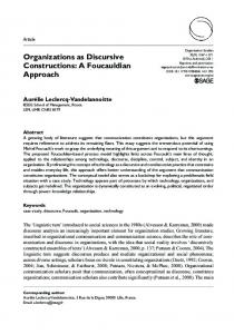
2.3 The Hybrid Approach for Particle Tracking Microrheology The hybrid approach combines the main steps of the TPM algorithm for those particles in focus with an additional circle detection algorithm for those out of focus halos. Figure 1 shows the flow graph of the proposed approach.
Peak Find
Centroids Find
_ Mask
Hist. Equalizer
Smooth Filter
Centroids Merge
Circle Detection
Tracking
Figure 1. The flow graph of the hybrid approach for particle tracking microrheology.
“Bypass Filter”, “Peak Find” and “Centroids Find” are the same as those in the TPM algorithm. The optimal threshold is chosen automatically based on the histogram of the greyscale image converted from the input video frame. The detected centroids correspond to the positions of these bright particles which are in focus. A mask is calculated with a size a little larger than the particle size and it is applied to the bypassed image in order to remove those bright particles in focus. A histogram equalizer has been employed to increase the intensity contrast, since the halos are dimmed with less intensity contrast to the background compared to those bright particles. A smooth filter follows to remove some small fractions. The centroids and the radius of those halos with enough contrast and within a pre‐defined size range are obtained by the circular HT circle detection algorithm (see Section 2.2). www.intechopen.com
Two sets of centroids are merged together. Certain criteria are adopted in this process to eliminate spurious or unwanted particles. For example, the limit of the displacement length is set for the particle to move between two consecutive frames. Normally, it is a small number. It also assumes that two particles do not collide. Furthermore, a polystyrene bead is typically represented by a disc‐like shape of at least some minimum number of connected components. Those positions that do not meet the criteria are discarded. The final list of centroids in each frame is fed into the tracking algorithm. Thus, all the particles’ trajectories are found. 3. Experiments and Results The fluorescent imaging datasets used in this paper were obtained from professor William Ryu. In the experiment, several polystyrene spheres were suspended in water, undergoing Brownian motion. The video microscopy data was taken with every t 0.5 second per frame. The Liangjun Xie, Nong Gu, Zhiqiang Cao and Dalong Li: A Hybrid Approach for Multiple Particle Tracking Microrheology
3
datasets contain a sequence of two hundred 640‐by‐480 colour JPEG images and have R, G and B values within [0, 255]. Those polystyrene spheres have a diameter of about 10 pixels. All of these frames are transferred to a greyscale intensity image. The histogram and intensity profiles show that those bright particles in the image (corresponding to the particles in focus) have an intensity of more than 70. Figure 2(a) shows the original micrograph. There are many halos that have a good circular shape and the intensity contrasts to the background are good enough to accurately detect the centroids of these particles. Figure 2(b) is the result of a bypass filter and thresholding at intensity 70 in the TPM. There are 13 particles that are in focus. From the video, some of the particles that are in focus are turned into halos while some halos turn into bright parts. Some are moved out of the screen. All of these conditions lead to the end of the tracking trajectories in the TPM algorithm. The Matlab implementation of TPM can be downloaded from [12].
fractions. The circular HT is processed in the modified image. Therefore, there is no conflict between those particles that are in focus and the detected halos. These two sets of centroids which have been found are merged together for tracking.
1 1 1 1 36 1 1
1 1 1 1 2 2 2 1 2 4 2 1 2 2 2 1 1 1 1 1
Figure 3. Weighted average smooth spatial filter for the modified image.
Figure 4. Additional particles detected by the circle detection algorithm with gradient threshold 4. The labels represent the pixel position in the 640‐by‐480 image.
(a)
(b)
4
Figure 2. (a) the original image, (b) the results of bypass filter and threshold at intensity 70 in TPM.
Figure 5. Additional particles detected by the circle detection algorithm with gradient threshold 8.
In the hybrid approach, in each frame, all of the particles that are in focus are detected by the TPM and they are then masked by a rectangle larger than the size of the particle. A linear histogram equalizer has been adopted to improve the intensity contrast of the halos to the background ‐ i.e., each pixel has 8 times the original intensity. Figure 3 shows the weighted average smooth spatial filter which is used to remove some small
In the circle detection step of the proposed approach, the possible minimum and maximum radii of the circles to be searched are 6 pixels and 65 pixels. The threshold of the gradient magnitude of the image is 4. It is performed to remove the uniform‐intensity image background before the voting process of the circular HT. In other words, pixels with gradient magnitudes smaller than the threshold are not considered in the computation. The
Int J Adv Robotic Sy, 2013, Vol. 10, 117:2013
www.intechopen.com
selected threshold controls the number of circles detected. If it is too small, some dimmed circles will be detected; however, they are hardly likely to be positioned accurately. On the other hand, if it is too large, few circles will be detected. Figure 4 shows 13 detected circles with gradient threshold 4, while in Figure 5 only 8 circles are detected when the gradient threshold is set to 8. The detected circles are drawn in blue and the corresponding centroids are marked by “+” with red in Figure 4. The radius of the filter is 20 pixels, which is used to search the local maxima in the accumulation array. It needs to be set larger when the circular shapes are less perfect. Considering that halos with or without kernels have three or two concentric circles separately, multiple radii may be detected corresponding to a single centre position. The argument of the tolerance to pick up the likely radii values is set as one, which means that the ʺprincipalʺ radius will be picked up. In addition to the 13 particles detected by TPM, there are another 13 particles detected by the circle detection, as shown in Figure 4. These additional detected circles have a higher intensity than the background but may be less than the threshold in TPM; thus, they are excluded by TPM. From both Figure 2 and Figure 4, each detected circle has good shape; hence, its position can be accurately calculated. The Matlab implementation for the circular Hough transform circle detection algorithm can be downloaded from [13].
demonstration, as shown in Figure 6. From frame 1 to frame 14, it is out of focus, and then moves in, moves out, and moves back into focus. The particle moves out of screen at frame 68. Figure 6(a) is the trajectory by the TPM which starts from frame 14 to frame 44. Figure 6(b) is the trajectory found by the proposed approach from frame 1 to frame 67. The trajectory within the red ellipse in Figure 6(b) is the same as that in Figure 6(a). Figure 6(c) plots the two trajectories together. The hybrid algorithm dramatically extends the particle’s trajectory from 31 frames to 67 frames. This result confirms the advantages of the hybrid approach. Defining the length of the tracking trajectory as the number of frames that the particle is detected successively, Table 1 shows the tracking results for both the TPM and the hybrid approach. The second row is the total length of all the detected tracking trajectories. TPM has 2,364 frames, while the proposed approach has 4,502 ‐ almost double. In total, TPM found 174 trajectories while the hybrid approach found 89. The average length of a TPM trajectory is 13.6 while the proposed approach has 50.6 ‐ much longer than that with TPM. The row “Number of trajectories > 5” lists the number of trajectories whose length is longer than 5 frames; the TPM has 92 trajectories while the hybrid approach found 87. This confirms the advantages of the hybrid approach. It not only reduces the number of the detected trajectories but also elongates those trajectories.
(a) (b)
TPM
Total length of tracked trajectories 2364 (frame) Total number of trajectories 174 Number of trajectories > 5 92 Average length for each trajectory 13.6 (frame)
The Hybrid Approach 4502 89 87 50.6
Table 1. Comparison of the experimental results of the hybrid approach and TPM.
4. Conclusions and Discussion
(c) Figure 6. Trajectory for the particle in row 340, column 58 in the first frame micrograph. (a) The trajectory found by TPM from frame 14 to frame 44. (b) The trajectory found by the proposed approach from frame 1 to frame 67. (c) Merged plot. The labels represent the pixel positions of the trajectory in the 640‐by‐480 images.
The particles’ positions in each frame are linked together to form trajectories. As an example, the particle in row 340, column 58 in the first frame was selected for www.intechopen.com
TPM uses a threshold to find those particles with peak and thus out of focus halos are excluded in those frames even though they are circular and their centres can be accurately tracked visually. Thus, the particle trajectories are broken. When the particles are sparse, TPM loses some useful information and may lead to inaccurate microrheology. In this paper, a hybrid approach for multiple particle tracking is proposed to overcome the disadvantages of TPM. It combines the steps of TPM for those particles in focus with an additional circle detection algorithm for those which are out of focus. After achieving the centroids by TPM, a mask is employed to each particle which is in focus. Then, a histogram equalizer is used to improve the contrast of the halos with the background. A spatial smooth filter follows to remove Liangjun Xie, Nong Gu, Zhiqiang Cao and Dalong Li: A Hybrid Approach for Multiple Particle Tracking Microrheology
5
the fractions. The circular HT is then adopted to find the centroids of those circles with good shape in the modified image. Finally, the two sets of centroids are merged together for tracking. The final list of centroids in each frame is fed into the tracking algorithm. Accordingly, all the particles’ trajectories are found. Experiments confirmed that the proposed hybrid algorithm not only reduces the number of trajectories, but also greatly elongates the particle’s trajectories with satisfactory accuracy. Future work will consider the application of super‐ resolution [14] to increase image quality and the application of the proposed approach to video surveillance, robot navigation and multi‐agent planning. 5. Acknowledgements We would like to thank Professor William Ryu of the University of Toronto for sharing the data set with us. 6. References [1] Z. Cao, L. Xie, B. Zhang, S. Wang and M. Tan, Formation Constrained Multi‐Robot System in Unknown Environment, Proc. of IEEE International Conference of Robotics and Automation (ICRA 03), Taiwan, pp. 735‐740, 2003. [2] S. Tsuji and F. Matsumoto, Detection of Ellipses by a Modified Hough Transformation, IEEE Trans. Comput. 27, 777‐781. 1979. [3] L. Xu, E. Oja and P. Kultanen, A New Curve Detection Method: Randomized Hough Transform, Pattern Recognition Letters. 11(5), 331‐338, 1990. [4] G. M. Schuster and A. K. Katsaggelos, Robust Circle Detection Using a Weight MSE Estimator, Proc. of
IEEE International Conference on Image Processing (ICIP 04). Vol. 3. Singapore, pp. 2111‐2114, 2004. [5] J. Illingworth and J. Kittler, The adaptive Hough Transform, IEEE Trans. Pattern Anal. Mach. Intell. 9(5), 690–698, 1987. [6] T. Peng, A. Balijepalli, S. K. Gupta and T. Lebrun, Algorithms for On‐Line Monitoring of Micro Spheres in an Optical Tweezers‐Based Assembly Cell, Transactions of the ASME. 7, 330‐338, 2007. [7] J. C. Crocker and B. D. Hoffman, Multiple Particle Tracking and Two‐Point Microrheology in Cells, Methods in Cell Biology. 83, pages 141‐178, 2007. [8] L. J. Bonales, H. Ritacco, J. E.F. Rubio, R. G. Rubio, F. Monroy and F. Ortega, Dynamics in Ultrathin Films: Particle Tracking Microrheology of Langmuir Monolayers, The Open Physical Chemistry Journal. 1, 25‐32, 2007. [9] A. J. Levine and T. C. Lubensky, Response Function of a Sphere in a Viscoelastic Two‐Fluid Medium, Physical Review E. 63(4), 2001. [10] T. G. Mason, Estimating the Viscoelastic Moduli of Complex Fluids Using the Generalized Stokes‐ Einstein Equation. Rheologica Acta. 39, 371‐378, 2000. [11] M. L. Gardel, F. Nakamura, J. Hartwig, J. C. Crocker, T. P. Stossel and D. A. Weitz, Stress‐Dependent Elasticity of Composite Actin Networks as a Model for Cell Behavior, Physical Review Letters. 96, 2006. [12] http://physics.georgetown.edu/matlab/tutorial.html [13] ftp://ftp.cs.princeton.edu/pub/cs126/atomic [14] L. Xie, D. Li, S. J. Simske, Feature Dimensionality Reduction for Example‐based Image Super‐ resolution, Journal of Pattern Recognition Research. 2, 130‐139, 2011.
6
Int J Adv Robotic Sy, 2013, Vol. 10, 117:2013
www.intechopen.com