A Hybridized Genetic Parallel Programming based Logic Circuit Synthesizer Wai Shing Lau
Kin Hong Lee
Kwong Sak Leung
Department of Computer Science & Engineering, The Chinese University of Hong Kong, Hong Kong
Department of Computer Science & Engineering, The Chinese University of Hong Kong, Hong Kong
Department of Computer Science & Engineering, The Chinese University of Hong Kong, Hong Kong
[email protected]
[email protected]
[email protected]
ABSTRACT
IOB
Genetic Parallel Programming (GPP) is a novel Genetic Programming paradigm. Based on the GPP paradigm and a local search operator - FlowMap, a logic circuit synthesizing system integrating GPP and FlowMap, a Hybridized GPP based Logic Circuit Synthesizer (HGPPLCS) is developed. To show the effectiveness of the proposed HGPPLCS, six combinational logic circuit problems are used for evaluations. Each problem is run for 50 times. Experimental results show that both the lookup table counts and the propagation gate delays of the circuits collected are better than those obtained by conventional design or evolved by GPP alone. For example, in a 6-bit one counter experiment, we obtained combinational digital circuits with 8 four-input lookup tables in 2 gate level on average. It utilizes 2 lookup tables and 3 gate levels less than circuits evolved by GPP alone.
Ram
R IOB a m
CLB
CLB
CLB
CLB
CLB
CLB
CLB
CLB
CLB
R a IOB m
Routing resources
Ram IOB
Categories and Subject Descriptors
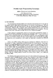
Figure 1: General Model of an FPGA which consists of Configurable Logic Blocks (CLBs), Input Output Blocks (IOBs) and routing resources
I.2.2 [Artificial Intelligence]: Automatic Programming; B.6.3 [Hardware]: Logic Design—Design Aids
General Terms Algorithms, Performance and Experimentation
Keywords Field Programmable Gate Array, Technology Mapping, LookUp table, Genetic Parallel Programming, FlowMap, A Hybridized Genetic Parallel Programming Logic Circuit Synthesizer
1.
INTRODUCTION
Field Programmable Gate Arrays (FPGAs) are a class of programmable hardware devices which consist of an array of Input Output Blocks (IOBs), Configurable Logic Blocks (CLBs) and routing resources. IOBs are responsible for
Permission to make digital or hard copies of all or part of this work for personal or classroom use is granted without fee provided that copies are not made or distributed for profit or commercial advantage and that copies bear this notice and the full citation on the first page. To copy otherwise, to republish, to post on servers or to redistribute to lists, requires prior specific permission and/or a fee. GECCO’06, July 8–12, 2006, Seattle, Washington, USA. Copyright 2006 ACM 1-59593-186-4/06/0007 ...$5.00.
839
connection between the inside logic and the outside world. CLBs is a basic unit of logic function implementation in FPGAs. Routing resources interconnect the Logic Circuits (LCs) and form connections between the LCs and the IOBs. Some FPGAs may contain on-chip RAM. A simplified general model of an FPGA is shown in Fig. 1. Lookup table (LUT)-based FPGAs are a new generation of integrated circuit with an array of programmable logic blocks placed in an infrastructure of interconnections. Fig. 2 shows a 2-Slice Virtex-E CLB [2] which contains two logic cells. Each Logic Cell consists of a function generator implemented as a LUT, a storage element or Flip Flop (FF), internal Carry and Control Logic and registers. A K-input LUT (K-LUT) can implement any Boolean function of up to K-variables. A typical design flow for FPGAs consists of a number of steps. We first apply logic synthesis and then follow by logic optimization. Then, it comes to technology mapping and finally placement and routing. The aim of FPGA technology mapping is to get a functionally equivalent LUT network based on a given Boolean circuit while placement and routing is to realize an implementation of the mapped LUT network. As a result, the objective of technology mapping is
MLP program in parallel assembly
decompile
truth table
training cases expected output evaluate fitness
evaluated outputs
registers
population
4-LUT GENETIC OPERATIONS:mutation, crossover, selection, etc... Evolution Engine (EE)
MLP program individuals
genotype
4-LUT
Multi-Logic-Unit Processor (MLP)
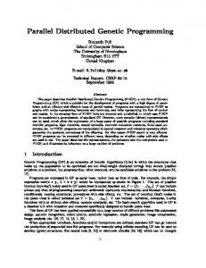
Figure 3: The system block diagram of the GPPLCS
there is still a room for improvement. Algorithms hybridize a non-genetic local search to refine the qualities of solutions with a genetic algorithm are called memetic algorithms. This inspires an idea of using a local search operator in GPPLCS. Since GPP is population-based, it has a number of individuals (circuits) that have the same function (i.e. many-to-one genotype-phenotype mapping). Thus, GPP can provide a number of different circuits as inputs to the FlowMap algorithm. In this way, FlowMap can return different mapping solutions so that a better solution can be obtained. Since FlowMap obtains a depth optimal mapping solutions when it is applied on 2-LUT Boolean circuit, GPP can first evolve circuits in 2-LUT and then relies on FlowMap to give a 4LUT mapping solution. This new GPPLCS with a local search operator - FlowMap becomes our HGPPLCS. This paper will focus on the effectiveness of the proposed HGPPLCS. We have performed experiments on six benchmark Binary arithmetic circuits (i.e. 2-bit full-adder, 3-bit comparator, 4-to-1 multiplexer, 6-bit priority selector, 3-bit multiplier and 6-bit one’s counter). Experimental results show that the HGPPLCS evolves better combinational digital circuits than conventional designs and current GPPLCS with smaller number of LUTs used and smaller depth. The rest of the paper is organized as follows: Section 2 contains descriptions of the current GPPLCS. Section 3 introduces FlowMap algorithm. Section 4 presents the HGPPLCS. Section 5 describes details of experiments and experimental settings. Section 6 presents results and discussions. Finally, section 7 concludes our work.
Figure 2: 2-Slice Virtex-E CLB
either to use a minimal chip area (i.e. area minimization) or to have a minimum circuit delay (i.e. depth minimization). The area is commonly indicated by the number of LUTs while the circuit delay is measured by the number of level of LUTs. The FlowMap algorithm [7] proposed by Prof. Jason Cong is a technology mapping algorithm for depth minimization in LUT-based FPGA designs, which is optimum for any K-bounded Boolean network. FlowMap can return a depth optimal mapping solution based on a given Boolean circuit. If we apply FlowMap to a group of Boolean circuits with same functionality, we will obtain different mapping solutions. Thus, an integration of Genetic Parallel Programming and FlowMap improves the mapping solution quality. Genetic Parallel Programming can be used to generate a pool of solutions while FlowMap can be used to generate the best solution. Among the pool of mapping solutions, a better circuit may be obtained. Genetic Programming (GP) [11] is a robust method in Evolutionary Computation. There are many streams in GP like graph-based GP, stack-based GP, Cartesian GP, linear-tree and linear-graph GP and grammar-based GP. The two main streams in GP are standard GP [12] and linear-structured GP (linear GP) [3]. In standard GP, a genetic program is represented in a tree structure. In linear GP, a genetic program is represented in a linear list of machine code instructions or high-level language statements. A linear genetic program can be run on a target machine directly without performing any translation process. The Genetic Parallel Programming (GPP) [13] paradigm is developed on the basis of linear GP. In GPP, a genetic parallel program consists of a sequence of parallel-instructions. A parallel-instruction comprises multiple sub-instructions that can perform multiple operations simultaneously in an execution step. A Genetic Parallel Programming based Logic Circuit Synthesizer (GPPLCS) is applied to solve the technology mapping problems. It is a combinational logic circuit learning system based on GPP. GPPLCS is different from the traditional algorithm which starts from a given circuit. Instead, GPPLCS evolve circuits from its functional description - truth table. Cheang et al. [6] have demonstrated that GPPLCS can be used to evolve combinational logic circuits with 2-input logic units. It can further be extended to evolve combinational logic circuit with 4-input lookup tables. Although the qualities of evolved combinational digital circuits from GPPLCS are better than conventional designs,
2. GENETIC PARALLEL PROGRAMMING LOGIC CIRCUIT SYNTHESIZER Genetic Parallel Programming (GPP) is a linear GP paradigm that evolves parallel programs based on a Multi-ALU Processor (MAP). GPP has been used to evolve compact parallel programs for different problems, such as numeric function regression [13] and data classification problems [5]. The GPP accelerating phenomenon [14] revealed that parallel programs can be evolved with less computational efforts relative to its sequential counterpart. This phenomenon allows a new two-step approach: 1) evolves a solution in a highly parallel program format; and 2) serializes the parallel program to a functionally equivalent sequential program. Based on GPP, a combinational logic circuit design system, GPP+MLP [6], was developed. Different combinational logic circuits were evolved with 2-input lookup-tables (2-LUTs). The core of the GPP+MLP system consists of
840
64 A B C D A B C D
L0
1
R0
L15
1
R15 R16
constants & inputs
R31 single-bit registers
1
1 1
1
64 bits
Figure 5: Individual representation in GPP
Figure 4: The 4-LUT MLP used by the GPPLCS an Evolution Engine (EE) and a Multi-Logic-Unit Processor (MLP) (see Fig. 3). The EE manipulates the genetic parallel programs and performs genetic operations. The MLP evaluates the genetic parallel programs to determine their fitness. The major enhancement of the GPPLCS was that we adopted a 4-LUT (instead of 2-LUT in the GPP+MLP) as the basis functional unit. The evolved 4-LUT network can be directly implemented on most commercial FPGAs. For the following subsections, 4-LUT GPPLCS is adopted for description unless specified otherwise.
Figure 6: A sub-instruction - SI interpretation
tion of an individual and Fig. 6 shows the representation of a SI which resembles a lookup table in the FPGA circuit. The evolved circuit will be printed in human readable form. It is called MLP program. The genotype of a genetic parallel program was loaded and executed in the MLP directly without pre-evaluation correction. This is possible because all Boolean function outputs are Boolean variables. This closure property is especially important for the GPPLCS because of its random nature based on evolutionary technique. The phenotype of an MLP program can be expressed as a parallel assembly program (see Fig. 7). As shown in the Fig 7, an MLP program consists of two sections, the #data and the #program sections. The #data section defines constants, inputs and outputs. Before starting an execution, the MLP always initializes all variable registers (R0-R15) to logic ’0’. The CONSTANTS line initializes read-only registers R16-R21 to logic ’0’ and R22-R26 to logic ’1’. The INPUTS line defines input variables (Cin, A1, A0, B1 and B0) and assigns them to read-only registers (R27-R31). The OUTPUTS line defines output variables (Cout, S1 and S0) and assigns them to variable registers (R0R2). The #program section contains parallel-instructions that perform Boolean operations. For example, the numbered lines in the #program section in Fig 7 list out two parallel-instructions. For easy interpretation, all nop (no operations) sub-instructions are removed from the original
2.1 The Multi-Logic-Unit Processor The MLP used in the GPPLCS is a general-purpose, tightly coupled processor. It is used for executing Boolean circuits evolved in GPPLCS (i.e evaluation of genetic program in GPPLCS). As shown in Fig. 4, the MLP consists of 32 registers. R0-R15 are variable registers that store intermediate values and program outputs while R16-R31 are read-only registers that store program inputs and logic constants. A variable register can only be modified by a dedicated 4-LUT (e.g. L0 can write to R0 only). The 16 4-LUTs (L0-L15) perform logic operations. The EE will preload the program inputs and the constants into the read-only registers before a parallel program is executed.
2.2 The Evolution Engine The Evolution Engine (EE) manipulates the population, performs genetic operations, loads genetic programs to a MAP for fitness evaluations, calculates/reports statistics and decompiles the evolved solution program to a symbolic parallel assembly program (MAP program) and high-level language source codes. All combinational digital circuits presented in this paper are evolved by a two-stage (i.e. design and optimization stages) approach. Different sets of genetic operators including crossover, bit mutation and sub-instruction swapping are used in different stages. In the design stage, the GPPLCS system aims at finding a 100% functional program (correct program). The raw fitness is given by the ratio of unsolved training cases. In the optimization stage, the raw fitness then puts emphasis on the LUT count, the propagation gate delay and the program length. In other words, the major objective of the optimization stage is reducing the LUT count and then the propagation gate delay.
#data CONSTANTS:(r16-r21)=0,(r22-r26)=1 INPUTS: (r27,r28,r29,r30,r31)(Cout,S1,S0) #program 0: bF6E0 r31 r27 r08 r29 r00 1: b3AA4 r00 r28 r06 r30 r00, bCB9E r00 r28 r30 r21 r01, b849E r31 r27 r31 r29 r02
2.3 The Evolved Parallel Programs The individual representation of GPPLCS includes a sequence of parallel instructions (PIs). In each PI, there are several sub-instructions (SIs). Fig. 5 shows the representa-
Figure 7: A 2-bit full-adder evolved by the GPPLCS
841
Input(4 Registers’ value)
Output
0000
0
0001
0
0010
0
0011
0
0100
0
0101
1
0110
1
0111
1
1000
0
1001
1
1010
1
1011
0
1100
1
1101
1
1110
1
1111
1
Refined by FlowMap
Found by GPPLCS
Figure 11: FlowMap refines the fitness of individuals in GPPLCS
Figure 8: The corresponding content of 4-LUT of the ”bF6E0 r31 r27 r08 r29 r00” sub-instruction
B0[r31] Cin[r27] A0[r29]
A1[r28] B1[r30]
0
F6 E0 0
0
84 9E
S0[r02]
3A A 4
Cout[r00]
C B9 E
S1[r01]
Figure 9: A 2-bit full-adder (four 4-LUTs in two levels) shown in Fig 7 program. Each sub-instruction consists of three parts: 1) a function name (b0000-bFFFF or nop); 2) four input registers; and 3) an output register. The Boolean function of each sub-instruction is denoted by a four-digit hexadecimal number which represents the 16-bit memory contents of the 4-LUT. For example, the bF6E0 r31 r27 r08 r29 r00 subinstruction in the parallel-instruction ”0:” is implemented by loading ”0000 0111 0110 1111” to the corresponding 4LUT which can be treated as a 16 to 1 multiplexer. The content of the corresponding 4-LUT is shown in Fig. 8. The corresponding 4-LUT network of the program is shown in Fig. 9.
3.
FLOWMAP ALGORITHM
FlowMap [7] is an LUT-based FPGA mapping algorithm for depth minimization guaranteeing depth-optimal mapping for a given input Boolean circuit. Since the working principle of FlowMap algorithm is not our focus, only a brief description of FlowMap is given. A key step in FlowMap algorithm is to compute a minimum height K-feasible cut in a network, which is solved optimally in polynomial time
based on network flow computation. FlowMap algorithm also effectively minimizes the number of LUTs by maximizing the volume of each cut and by several post-processing operations. FlowMap algorithm includes two phase, labeling phase and mapping phase. In the first phase, it computes a label for each node in the circuits which reflects the level of the K-LUT implementing that node which reflects the level of the K-LUT implementing that node in an optimal mapping solution. In the second phase, it generates the K-LUT mapping solution based on the node labels computed in the first phase. It should be noted that FlowMap gets a better mapping solution when a 2-LUT Boolean circuit is given as an input. As a result, it gives an opportunity of adopting FlowMap in GPPLCS.
4. A HYBRIDIZED GENETIC PARALLEL PROGRAMMABLE LOGIC CIRCUIT SYNTHESIZER As stated before, FlowMap will return a depth optimal mapping solution for a 2-LUT Boolean circuit input and hence is a very suitable tool to help GPPLCS to locate the local optimum. Since GPPLCS can provide a population of 2-LUT Boolean circuits with same functionality, FlowMap can give a best mapping solution among all the mapping solutions. We will describe HGPPLCS below. HGPPLCS first evolves 2-LUT Boolean circuits. Then among the population of the 2-LUT Boolean circuits, the best one is chosen for FlowMap input. Finally, FlowMap will give a 4-LUT mapping solution (see Fig. 10). The synergy effect of GPPLCS and FlowMap in HGPPLCS is well established that evolutionary algorithms are not well suited to fine tuning greedy local search in complex combinatorial spaces and that hybridization with other techniques can greatly improve the efficiency of search [8, 9, 10, 15]. FlowMap can be applied to significantly improve GPPLCS by obtaining the local optimal circuits efficiently and effectively (see Fig.11). The population-based GPPLCS provides FlowMap with a group of diversified Boolean circuits with same functionality which cannot be obtained by any deterministic algorithms. In this way, a global optimal circuit can be evolved with efficiency and global search power from FlowMap and EA respectively.
5. DETAILS OF EXPERIMENTS AND EXPERIMENTAL SETTINGS HGPPLCS has been evaluated on six problems. They are 2-bit full adder (ADD2), 6-bit comparator (CMP3), 4-
842
GPP
–
Evolution Engine Genetic Operators: Crossover, Mutation etc
Multi - ALU Processor (MAP) Programs Evaluation
–
4 - LUT circuits
2 - LUT circuits FlowMap Optimization
Figure 10: HGPPLCS
Table 1: Six combinational logic circuit problems. The Nin and Nout denote the numbers of inputs and outputs respectively. The Nrow (=2Nin )denotes the number of rows in the truth tables . The Ncase (=Nrow × Nout )denotes the total number of training cases . Name Description Nin Nout Nrow Ncase ADD2 2-bit full-adder 5 3 32 96 CMP3 3-bit comparator 6 3 64 192 MUX6 6-bit multiplexer 6 1 64 64 PSL6 6-bit priority selector 6 4 64 256 MUL3 3-bit multiplier 6 6 64 384 OCN6 6-bit one’s counter 6 3 64 192
Table 2: Experimental settings both design and optimization stages maximum program 25 parallel-instructions length initialization bit random, average 12.5 parallelinstructions selection method tournament (size=10) 4-LUT function set b0000, . . . , bFFFF, nop 2-LUT function set b00, . . . , b15, nop inputs R32−Ninput . . . R31 outputs outputs: R0 . . . RNoutput−1 constants logic 0, logic 1 crossover Prob. 0.1 population size 2000 experiments 50 independent runs 20,000,000 tournaments termination(tmax )
to-1 multiplexer (MUX6), 6-bit priority selector (PSL6), 3bit multiplier (MUL3) and 6-bit one’s counter (OCN6) (see Table 1). They are all benchmark Boolean problems that are tried or appeared in other evolvable hardware approaches. Note that the 3-bit comparator compares two 3-bit binary input (A and B). Comparison results of the two 3-bit binary values are three output bits (”AB”). Then, the 6-bit priority selector is to show the position of value ’1’ which first appears starting from the least significant bit in the 6-bit input. If none of the bits is set to value ’1’, an extra output bit which shows the case of all zero value is responsible for this special case. Since we have got six input bits (Input5 - Input0), we need extra three bits to indicate the position. Therefore, there are 4-bit outputs. Finally, the 6-bit one’s counter is to calculate the number of value ’1’ in the 6-bit inputs. Therefore, it requires 3-bit to represent the number in the output. All experimental settings are listed in Table 2 below. Having investigated the difficulties of the six benchmark problems shown in Table 1, we set the maximum program length to 25 PIs. This provides enough sub-instructions (for both effective operations and introns) to evolve correct programs. Hence, at most 400 (25x16) operations can be used to build a solution. Noticeably, in the optimization stage, we force the system to optimize the size of the correct programs as much as possible. Thus, all runs terminate after 20,000,000 tournaments. In order to show the effectiveness of HGPPLCS, we have tried the six problems on GPPLCS and FlowMap. However, we have not compared with any evolvable hardware techniques like Cartesian GP due to the different circuits evolved. They are in boolean gate form (i.e., 2-input LUT) while we are focusing on 4-input LUT circuits. The GPPLCS adopts the same experimental settings as HGPPLCS which is shown in Table 2. To ensure a fair comparison
design stage bit mutation Prob. SI. swap. Prob. raw fitness
success predicate
0.002 0.0 the ratio of unsolved training cases all training cases solved
optimization stage 0.0 0.5 the ratio of gate level & LUT count optimize as much as possible
between HGPPLCS and GPPLCS, all evolutions of combinational logic circuits for the six combinational logic circuit problems are run on the same PC configuration (Pentium 4 CPU 2.80GHz with 512 MB RAM) with 50 independent runs. The only difference is in the types of circuits evolved. GPPLCS evolved the circuits with 4-LUT while HGPPLCS evolved the 2-LUT type. Since the difficulty for evolving 2-LUT and 4-LUT Boolean circuits in each problem are different, numbers of tournaments are not presented in this paper. Results from FlowMap algorithm are collected from the experiments which were run on UCLA RASP FPGA/CPLD Technology Mapping and Synthesis Package [1]. Firstly, we used the ESPRESSO [4] to optimize the truth tables of the six Boolean problems into optimal (or near optimal) sum of product (SOP) forms. Then the resulting SOP expressions were passed to produce 4-LUT networks with the FlowMap algorithm.
843
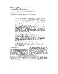
Average number of 4-LUT count and gate levels collected in 50 independent run 25 20
Number
Table 3: Best circuits collected from HGPPLCS, GPPLCS and FlowMap algorithm on six problems Version Type ADD2 CMP3 MUX6 PSL6 MUL3 OCN6 HGPPLCS Gate 4 5 2 5 15 7 Level 2 2 2 2 3 2 GPPLCS Gate 4 6 2 5 15 6 Level 2 3 2 3 4 3 FlowMap Gate 16 23 3 11 50 113 Level 3 3 2 3 3 4
avg Gate by HGPPLCS
15
avg Gate by GPPLCS avg Level by HGPPLCS avg Level by GPPLCS
10 5 0
ADD2 CMP3 MUX6 PSL6 MUL3 OCN6
Table 4: Successful rate of evolving circuit problems in HGPPLCS and GPPLCS Version ADD2 CMP3 MUX6 PSL6 MUL3 OCN6 HGPPLCS 100% 100% 100% 100% 50% 58% GPPLCS 100% 100% 100% 100% 54% 100%
6.
Six Problems
Figure 12: Average number of 4-LUT count and gate level collected from HGPPLCS and GPPLCS on the six problems in 50 runs
RESULTS AND DISCUSSIONS
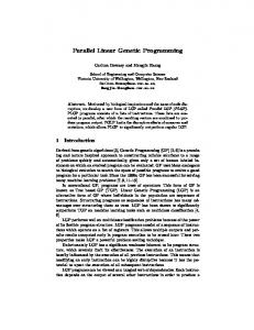
Best circuits (in terms of number of 4-LUT count and gate levels) collected in 50 independent run
From the 50 runs of the six individual problems, it is shown that HGPPLCS evolved the best circuits among the three methods (HGPPLCS, GPPLCS and FlowMap). Table 3 shows the best circuits collected from the three methods and Table 4 indicates the successful rate of evolving circuits in HGPPLCS and GPPLCS. Since FlowMap depends heavily on the given input circuits, the mapping solution will not be of a good quality if the input circuits provided are in a bad form (e.g in SOP forms). As FlowMap is a deterministic algorithm, the mapping solutions are always the same regardless of the number of times it is tried. Thus, it is not shown in the charts about comparison between HGPPLCS and GPPLCS. Fig. 12 is the average values of the circuits evolved (in terms of 4-LUT count and gate level) collected in the 50 independent run of HGPPLCS and GPPLCS while Fig. 13 is the best circuit evolved in the 50 run of HGPPLCS and GPPLCS. Obviously, the HGPPLCS successfully improves the GPPLCS. On the six problems, both the average number of LUT count and gate level in the circuits evolved from HGPPLCS are smaller than that from GPPLCS. Although HGPPLCS may not get a better circuit than GPPLCS in all six problems, HGPPLCS performs as well as GPPLCS. In the 3-bit comparator problem (CMP3), the best circuit evolved from HGPPLCS is 1 4LUT and 1 gate level less than the one from GPPLCS. The circuit is shown in Fig. 14. It is found that the circuits evolved from HGPPLCS may have a greater number of 4-LUT count than the ones from GPPLCS. In the 6-bit one’s counter problem (OCN6), although the best circuit evolved from HGPPLCS is 1 gate level less than the one from GPPLCS, it utilizes 1 4-LUT more. The reason lies on the FlowMap algorithm. Since FlowMap only guarantees a depth optimal mapping solution on a given input circuit, the number of 4-LUT of the solution may not be smaller than the circuit found in GPPLCS. However, the depth of the circuit is always the smallest. HGPPLCS shows a perfect synergy between GPPLCS and FlowMap. The population based GPPLCS provides FlowMap with a group of diversified Boolean circuit with the same functionality while FlowMap returns a better mapping solutions than GPPLCS.
16 14
Number
12 10
best Gate by HGPPLCS
8
best Gate by GPPLCS best Level by HGPPLCS
6
best Level by GPPLCS
4 2 0
ADD2 CMP3 MUX6
PSL6
MUL3 OCN6
Six Problems
Figure 13: Best number of 4-LUT and gate level collected from HGPPLCS and GPPLCS on the six problems in 50 runs Although HGPPLCS outperforms GPPLCS, the successful rate of both approaches are nearly the same. From the rate shown in Table 4, it is found that the MUL3 and OCN6 problems are more difficult than others. As HGPPLCS first evolves circuit in 2-LUT form and then relies on FlowMap to give a 4-LUT mapping, the searching space in HGPPLCS is much larger than those in GPPLCS which evolves 4-LUT instead. Thus, it is expected that the successful rate of HGPPLCS is lower or equal to that of GPPLCS.
7. CONCLUSION AND FUTURE WORK In this paper, we have presented a Hybridized Genetic Parallel Programming Logic Circuit Synthesizer (HGPPLCS). It makes use of a Genetic Parallel Programming Logic Circuit Synthesizer (GPPLCS) and FlowMap algorithm. HGPPLCS applies a two-stage approach to evolve a 2-LUT circuit. Then the circuit is passed to FlowMap. Finally, FlowMap returns a depth optimal mapping solution regarding the given input circuit. Experimental results show that HGPPLCS improves the performance of GPPLCS. The qualities
844
A2[r26] A1[r27] B2[r29] B1[r30]
84 21 8D EF
A0[r28] B0[r31]
0
41 00 66 54 B A B B
A=B[r01]
A>B[r02]
A