like a classic register defined everywhere in the description. (i.e. CP ... of hardware components and the definition of the pipeline. It ..... It is a 16 bits RISC co-.
Jul 2, 2018 - methods; (b) initial makers of MSRM; (c) GAC; (d) CV; (e) SBGFRLS; ...... Segmentation results of 'plane' image with different initial contours: (a) ...
... Quantum Correction Models for the Three-Dimensional Simulation of FinFET Structures. R. ENTNER*, A. GEHRING°, T. GRASSER*, AND S. SELBERHERR°.
Oleh Dzyubachyk, Wiro Niessen and Erik Meijering. Biomedical Imaging Group ... Recent efforts in this area have revealed the potential of model evo- ... roughly be divided into two main classes [3, 4]. The first ... proposed by Chan and Vese [6]. Thi
Segmentation of Skin Lesions using Level Set Method. Zhen Ma, João Manuel R. S. Tavares. Instituto de Engenharia Mecânica e Gestão Industrial,. Faculdade ...
of the image's level curves while still maintaining image fi- delity. This is ..... Principles of Digital Image Synthesis. Mor- gan Kaufmann, 1995. [10] B. Kimia, A.
for applications such as video telephony. The actual segmentation methods are not part of the MPEG-4 standards and are left to the implementers to develop ...
David Keppel. University ... called Shade which combines efficient instruction-set
simulation .... chronization instructions and Shade arbitrarily limits the number.
Abstract—We present HORNET, a parallel, highly configurable, cycle-level
multicore .... cannot be used to guide architectural decisions on a. 1000-core
scale;.
of artificial societies harmoniously reunites and develops in a correlated manner the domains of artificial intelligence and artificial life. The research in this field is ...
15. XVII The People (so far) behind the development of the simulator. 15 .... It applies to ACKnowledgments (ACKs), CQI, Precoding ..... Added âCompanies (no matter profit-oriented or not) are not allowed for free usage .... II Model website, downl
the Massachusetts Institute of Technology, Cambridge, MA 02139 USA. (e-mail: [email protected]; [email protected]; ksshim@csail. mit.edu ...
Mar 3, 2016 - 3Department of Earth System Science, University of California Irvine, Irvine, CA, USA ... Revised: 13 February 2016 â Accepted: 16 February 2016 â Published: 3 .... sal calving rate parameterization exists to date (Benn et al.,.
Jan 29, 2018 - antoinelaurain.com/compliance.htm, and the main file is also given in the appendix. 1. ...... We refer to the monographs [33, 39] for a complete .... The code can be downloaded at http://antoinelaurain.com/ ... python compliance.py can
Mar 3, 2016 - late the calving front thickness onto the ice-free domain us- .... the start of each year, plotted over basal topography (grey). Table 2. Table of experiments. Name ... calving front positions and their shape are in good agreement.
Topology optimization is also a kind of shape optimization problems but allows ..... [4] Bendsøe M. Optimal shape design as a material distribution problem.
RRM mechanisms include Call Admission Control (CAC),. Handover ... Business City Centre Environment (micro-cellular) and the Urban/Vehicular Environment.
provided in the form of flat files (ASCII text) which can be easily imported into most ..... (11) where V is the vertical exaggeration (scale). In general, if the sensor ...
In this paper, we develop a cell-level/call-level ATM switch simulator ... If all input calls are assumed to be homogeneous CBR services and the ... cell in an ALS is destined to the output port of another ALS, then it is switched through the ACS to
providing a direct link between process technology and circuit ..... in the development of ASIC's and MEMS for automotive applications. .... Associate Professor.
successfully apply our full-system simulator to a MEMSWear-. Biomonitoring
application. The simulation results, together with a set of investigative guidelines,
...
vi. 9. OUTPUT FROM TMVOC . ..... Figure 10.4.5 Portion of TMVOC input file for part 3 of problem 4 (TCE injection) ............... 80. Figure 10.4.6 Portion of ..... The Henry's coefficients for NCG dissolution in the aqueous phase are calculated as
We use â and ¬ to denote explicit and default negation respectively. A HLNM program is a set of program rules (also called clauses). We adopt four constructors: ...
Email: filipovic|selberherr@iue.tuwien.ac.at. AbstractâAtomic force microscopy (AFM) can be used as a lithographic technique capable of manufacturing ...
11-3
A Level Set Simulator for Nanooxidation using Non-Contact Atomic Force Microscopy L. Filipovic∗† and S. Selberherr∗ ∗ Institute
for Microelectronics, TU Wien, Gußhausstraße 27–29/E360, A-1040 Wien, Austria † Christian Doppler Laboratory for Reliability Issues in Microelectronics Email: filipovic|[email protected]
Abstract—Atomic force microscopy (AFM) can be used as a lithographic technique capable of manufacturing nanometersized devices. A simulator for AFM, implemented in a Level Set environment, is presented. The simulator uses empirical models to deduce the shape of a desired nanodot based on the applied voltage, pulse time, and ambient humidity. The shape of an AFM nanowire depends on the same factors as the shape of the nanodot in addition to the wire’s orientation with respect to the (010) direction. An advantage of the presented approach is the ease with which further processing steps can be simulated in the same environment. Sample oxide nanodots and nanowires are analyzed, showing the ability of the process to generate nanometer sized structures.
I. I NTRODUCTION Conventional photo-lithographic methods are not able to accurately describe the processing steps required for nanolithography of modern devices, such as those manufactured with the aid of an atomic force microscope (AFM) [1], shown in Figure 1. AFM was initially developed as a method to detect depressions and protuberances on a nanometer sized section of a sample surface [2] using the tunneling current between a conductive cantilever tip and a grounded sample surface. More
Fig. 1.
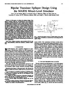
but also in physics, chemistry, biology, biochemistry, and other disciplines where the chemical or physical properties of a surface are required [10]. It is becoming critically important to properly model silicon surface deformations due to AFM, since simulating processing steps and the resulting features gives clues to the full potential of device processing with this method. A simulator for nanooxidation using NCM-AFM is presented, which considers the variation of the oxide structure as a function of the applied voltage, oxidation time, and ambient humidity. The presented work is incorporated into an existing Level Set simulator [11]. This allows for the surface to undergo a variety of processing steps before and after NCM-AFM within the same environment. II. NCM-AFM M ODELS A. Nanodot Model The relationship between the pulse time and applied voltage and the oxide nanodot height and width, calculated as the full width at half maximum (FWHM) as described in [12] is shown in Figure 2. This empirical relationship was programmed into the simulator as suggested in [13] and [14]. It can be deduced that a logarithmic relationship exists between the nanodot size and the pulse time, while a mainly linear relationship exists between the nanodot size and the applied voltage. In [6] and [7] the effect of humidity on the nanodot size is presented and the relationship is shown in Figure 3. The derived empirical equation, which describes the effect of all three parameters (time, voltage, and humidity) on the height and width of the oxide dot in nanometers, produced using NCM-AFM mode is shown in (1), where t is the pulse time in seconds, V is the applied voltage in volts, and h is the ambient humidity in percent.
Basic schematic of AFM oxidation.
recently, AFM has been used as a tool for local anodic oxidation of silicon surfaces, which has been used as a patterning tool for the deposition, removal, and modification of material surfaces with nanoscale precision, mainly for low volume manufacturing (LVM) [3]–[5]. The nanolithography of modern transistors using non-contact mode atomic force microscopy (NCM-AFM) is a promising method for the manufacture of the next generation of nanometer-sized devices [6]–[9]. AFM has been used extensively, not only in the semiconductor industry,
Effects of humidity on the nanodot height and width.
60
2
200
1.6
160
80
90
50 100
1.2
120
Height Width Measured H Measured W 0.8
0
0.2
0.4
Humidity (%)
Fig. 3.
14
300
2
30
12
350
1.5
0
10
Voltage (V)
Height Width Measured Height Measured Width
4 2
0.015
160
4
Time (s)
2.5
0.4
0.01
180
0.6
0.8
1
1.2
1.4
80 1.6
Angle (rad)
Fig. 4. Effects of time, voltage, humidity, and orientation on the nanowire height and width.
B. Nanowire Model III. NCM-AFM K INETICS In addition to the use of experimental observations in order to implement an empirical model for nanodots in the Level Set simulator, the simulator was also extended to include the generation of nanowires using NCM-AFM. From the experimental results found in [7], relevant information was extracted to include the effects on the nanowire shape due to variations in applied voltage, oxidation time, ambient humidity, and wire orientation, shown in Figure 4. The wire orientation is represented as an angle, where the (010) direction is 0o while (100) is 90o . It is evident that increasing the oxidation time, the applied voltage, or the ambient humidity results in an increased nanowire height and width. However, the effect of the wire orientation is less predictable. The empirical equation, derived using the experimental results from [7] and implemented in the Level Set simulator is given in (2), where t is the oxidation time in seconds, V is the applied voltage in volts, h is the ambient humidity in percent, and θ is the wire orientation in radians, represented as the angle between the nanowire and the (010) direction. In Figure 4 the results of our empirical equation (2) are compared to the experimental data from [7].
The procedure implemented to simulate NCM-AFM nanooxidation is similar to the procedure presented in [14]. The Monte Carlo method is used to distribute particles according to a Lorentzian distribution, which are then accelerated towards the silicon surface with ray tracing techniques. The simulator is implemented by first calculating the shape of the nanodot or nanowire with the previously mentioned empirical equations which depend on the oxidation time, applied voltage, ambient humidity, and nanowire orientation. Afterwards, a desired number of particles is distributed above the silicon surface, their position following the pattern of the desired surface deformation. Finally, each particle is accelerated towards the surface, causing it to collide with the wafer. Upon impact, the silicon dioxide is advanced deeper into the silicon, while it simultaneously grows into the ambient. The result is an oxide nanodot or nanowire having the desired height and width, depending on the processing variables of voltage, time, humidity, and orientation. A flow chart which summarizes the simulation steps is given in Figure 5.
- 308 -
Oxide Width (nm)
2
5
Oxide Height (nm)
Oxide Width (nm)
12
Oxide Height (nm)
1.6
Oxide Height (nm)
160
2.5
14
Height Width Measured Height Measured Width
6
Oxide Height (nm)
Height Width
3
Oxide Width (nm)
16
Oxide Width (nm)
2
Oxide Width (nm)
H(t, V, h, θ) = W (t, V, h, θ) =
Figure 6(c) shows the distribution of nanodot sizes caused by a variation of the ambient humidity. The pulse time and applied voltage were kept constant at 0.2ms and 20V respectively, while the humidity was set to 30%, 50%, 70%, and 90%. With an increasing ambient humidity, the nanodot height and width also increases, as expected. The height varied from 0.65nm to 2.07nm, while FWHM varied from 10.6nm to approximately 34nm with the ambient humidity set to 30% and 90%, respectively. The heights shown in Figure 6 are scaled by 20 for improved visualization. The results confirm the experimental results gathered from [6] and [12]. B. Nanowire Simulations Sample simulations of AFM nanowires are shown in Figure 7. Four wires are generated, each with a different orientation. The wires are generated at 0o , 30o , 60o , and 90o relative to the (010) direction. The results are summarized in Table 1, where it is evident that the nanowire height and width vary significantly due to a change in the nanowire orientation. All simulations were performed under identical conditions. The oxidation time was set to 0.1ms, the applied voltage was 7V, and the ambient humidity was 55%. Table 1. Summary of results for the AFM nanowire simulation with varying wire orientation (t=0.1ms, V=7V, h=55%).
Fig. 5. Flow chart of the simulation process implementing the Monte Carlo method with ray tracing in a Level Set environment.
IV. S AMPLE S IMULATIONS A. Nanodot Simulations Sample simulations of AFM nanodots are shown in Figure 6. Figure 6(a) shows the distribution of nanodot sizes caused by a variation of pulse times. The voltage and humidity were kept constant at 20V and 55%, respectively, while the time was set to 0.2ms, 0.3ms, 0.5ms, and 1ms. With increasing pulse times, the nanodot height and width also increases, as expected. The height varied from 1.24nm to 2.05nm, while FWHM varied from 15nm to approximately 50nm with pulse time set to 0.2ms and 1ms, respectively. Figure 6(b) shows the distribution of nanodot sizes caused by a variation of the applied voltage. The pulse time and humidity were kept constant at 0.2ms and 55%, respectively, while the voltage was set to 16V, 18V, 20V, and 22V. With an increasing applied voltage, the nanodot height and width also increases, as expected. The height varied from 0.51nm to 1.58nm, while FWHM varied from 10nm to approximately 18nm with the applied voltage set to 16V and 22V, respectively.
Orientation (010) 0o 30o 60o 90o
Height (nm) 1.07 1.93 1.30 1.19
FWHM (nm) 38.3 65.1 83.4 62.8
The smallest nanowire is noted at an orientation of 0o , where a height and FWHM of 1.07nm and 38.3nm, respectively, can be observed. The largest nanowire height is noted at 30o , while the largest FWHM is noted at 60o . The effect of the wire orientation on the height and width of the nanowire is not identical. The heights shown in Figure 7 are scaled by 100 for improved visualization. These simulations are confirmed by the experimental observations from [7]. V. C ONCLUSION AFM is used as a lithographic technique capable of manufacturing nanometer-sized devices. Our simulations of nanodots and nanowires using NCM-AFM in a generic Level Set simulator enable an easy integration with further processing steps. The model for the shape of a desired nanodot or nanowire is generated using empirical equations which describe the effect of various processing conditions on the nanostructure’s height and width. The nanodot size is influenced by the pulse time, applied voltage, and humidity, while the nanowire also depends on the orientation. Sample oxide nanodots and nanowires are simulated, showing the ability of the process to generate nanometer sized structures.
- 309 -
Fig. 6. Effects of time, voltage, and humidity on the nanodot height and width. The vertical axis is scaled by 20 for better visualization. The top surface represents the oxide-ambient interface, while the lower surface represents the oxide-silicon interface.
R EFERENCES [1] J. Dagata, J. Schneir, H. Harary, C. Evans, M. Postek, and J. Bennett, “Modification of Hydrogen-Passivated Silicon by a Scanning Tunneling Microscope Operating in Air,” Applied Physics Letters, vol. 56, pp. 2001–2003, May 1990. [2] G. Binning, C. F. Quate, and C. Gerber, “Atomic Force Microscopy,” Physical Review Letters, p. 930, 1986. [3] R. Mart´ınez, N. Losilla, J. Martinez, Y. Huttel, and R. Garcia, “Patterning Polymeric Structures with 2nm Resolution at 3nm Half Pitch in Ambient Conditions,” Nano Letters, vol. 7, pp. 1846–1850, Jul 2007. [4] G. Qin and C. Cai, “Sub-10-nm Patterning of Oligo (Ethylene Glycol) Monolayers on Silicon Surfaces via Local Oxidation Using a Conductive Atomic Force Microscope,” Nanotechnology, vol. 20, no. 35, p. 355306, 2009. [5] A. Notargiacomo and A. Tseng, “Assembling Uniform Oxide Lines and Layers by Overlapping Dots and Lines Using AFM Local Oxidation,” in Nanotechnology, 9th IEEE Conference on, Jul 2009, pp. 907–910. [6] P. Avouris, T. Hertel, and R. Martel, “Atomic Force Microscope TipInduced Local Oxidation of Silicon: Kinetics, Mechanism, and Nanofabrication,” Applied Physics Letters, vol. 71, pp. 285–287, Jul 1997. [7] T.-H. Fang, “Mechanisms of Nanooxidation of Si(100) From Atomic Force Microscopy,” Microelectronics Journal, vol. 35, no. 9, pp. 701– 707, 2004. [8] M. Johannes, D. Cole, and R. Clark, “Three-Dimensional Design and Replication of Silicon Oxide Nanostructures Using an Atomic Force Microscope,” Nanotechnology, vol. 18, p. 345304, Aug 2007. [9] J. Huang, C.-L. Tsai, and A. A. Tseng, “The Influence of the Bias Type, Doping Condition and Pattern Geometry on AFM Tip-Induced Local Oxidation,” Journal of the Chinese Institute of Engineers, vol. 33, no. 1, pp. 55–61, 2010. [10] Q. Tang, S.-Q. Shi, and L. Zhou, “Nanofabrication with Atomic Force Microscopy,” Journal of Nanoscience and Nanotechnology, vol. 4, no. 8, pp. 948–963, Nov 2004. [11] O. Ertl and S. Selberherr, “A Fast Level Set Framework for Large ThreeDimensional Topography Simulations,” Computer Physics Communications, vol. 180, no. 8, pp. 1242–1250, 2009. [12] M. Calleja and R. Garc´ıa, “Nano-Oxidation of Silicon Surfaces by Noncontact Atomic-Force Microscopy: Size Dependence on Voltage and Pulse Duration,” Applied Physics Letters, vol. 76, no. 23, pp. 3427–3429, 2000. [13] L. Filipovic, H. Ceric, J. Cervenka, and S. Selberherr, “A Simulator for Local Anodic Oxidation of Silicon Surfaces,” in 24th Canadian Conference on Electrical and Computer Engineering, May 2011, pp. 695–698. [14] L. Filipovic and S. Selberherr, “A Monte Carlo Simulator for NonContact Mode Atomic Force Microscopy,” in International Conference on Large-Scale Scientific Computations (LSSC), June 2011, pp. 42–43.
Fig. 7. Effects of wire orientation on the nanowire height and width, with t=0.1ms, v=7V, and h=55%. The vertical axis is scaled by 100 for better visualization. The top surface represents the oxide-ambient interface, while the lower surface represents the oxide-silicon interface.