Leece. Italy. (Received 15 February 1974; and in final form, 8 Apri11974). A lithium ion source of the Blewett-Jones type has been assembled and tested for.
A lithium ion source for cyclotron external injection A. Luches, L. Provenzano, and G. De Michele Citation: Rev. Sci. Instrum. 45, 1028 (1974); doi: 10.1063/1.1686798 View online: http://dx.doi.org/10.1063/1.1686798 View Table of Contents: http://rsi.aip.org/resource/1/RSINAK/v45/i8 Published by the AIP Publishing LLC.
Additional information on Rev. Sci. Instrum. Journal Homepage: http://rsi.aip.org Journal Information: http://rsi.aip.org/about/about_the_journal Top downloads: http://rsi.aip.org/features/most_downloaded Information for Authors: http://rsi.aip.org/authors
Downloaded 25 Sep 2013 to 202.116.1.148. This article is copyrighted as indicated in the abstract. Reuse of AIP content is subject to the terms at: http://rsi.aip.org/about/rights_and_permissions
1028
Notes
1028
A flow reading was first obtained from the fluid rise time in the pipette. Without changing the settings of the metering valves, the trap and pipette were disconnected at union F and replaced with a soap bubble meter. Flow measurements were made with valve B both open and closed, and the difference in the readings provided the true flow to the reactor. (The volume between valves A
and B was insignificant.) The ratio of the soap bubble flowmeter measurement to the fluid rise time reading was found to be 1.37 for the above system. Once such a calibration factor is determined, it can be used for all future measurements without redetermination, so long as the volume between the pipette, the toggle valve (C) and the reactor metering valve (A) remains unchanged.
A lithium ion source for cyclotron external injection A. Luches, L. Provenzano, and G. De Michele* Istituto di Fisica. Universita di Leece. Leece. Italy (Received 15 February 1974; and in final form, 8 Apri11974)
A lithium ion source of the Blewett-Jones type has been assembled and tested for radial injection into the CSATA cyclotron. Ion currents up to 1.5 rnA at the extractor are obtained. The extracted beam is focused at the cyclotron vacuum chamber port by a quadrupole doublet. The injected ion current is 500 p.A.
A lithium ion source has been designed and tested for external injection into the 1 MeV/nucleon sectored CSATN cyclotron. The source body and drift tube are designed to fit the cyclotron vacuum chamber. It is well known that thermoionic emission is a very effective method for producing Li+ ions. In fact, some aluminosilicates, heated up to a temperature slightly below their melting point, emit as ions the majority of their alkali atoms. It has been shown2 that beta-eucryptite (Li 20· AhOa' 2Si0 2) FEEDTHROUGHS
exibits the best emissive characteristics, giving out current densities up to 4 mA/cm2 when heated up to 1300°C, It is better to maintain the ion currents below 1 mA/cm2 to prevent a too rapid reduction of emissive compound, dangerous CO 2 gas bursts, and a too quick evaporation of neutral lithium atoms which, if stuck on insulating supports, may give rise to breakdowns or other troubles. Beta-eucryptite is prepared from the parent components AhOa, Li 2CO a, an'd Si02 according to the method of Couchet.a The components are milled and dosed in such chemical proportions that the reaction Li 2CO a+ 2Si0 2 + AhOa ~ Li0 2 • Al 20 a· 2Si0 2+C0 2
-
" "
c
i:
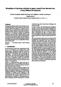
FIG. 1.
CYCLOTRON
Source outline.
PORT
Rev. Sci. Instrum., Vol. 45, No.8, August 1974
can occur fully at about 1450°C. This temperature is maintained for about 20 min. The obtained compound, glassy in appearance, is milled, diluted in ethyl alcohol, and smeared on the emitter holder. The holder is a tantalum plate, 0.1 mm thick, which does not react with beta-eucryptite at working temperatures. The target is heated in high vacuum (lo-L 10-6 Torr) up to 1400°C and then slowly cooled to obtain a smooth glassy layer, homogeneous in density and thickness, firmly stuck on the target. The source outline is shown in Fig. 1 and the electric circuit in Fig. 2. The filament, made of tungsten wire (4)= 1 mm), is carefully shaped to cover the whole target surface, placed 4 mm from the filament itself. The dissipated power is about 600 W. The emitter holder is a thin tantalum target triangular in shape, slightly concave to improve beam focusing. It is linked by three sharp stems to a circular tungsten support (4)= 1 mm) to minimize heat conduction. The emissive surface is about 3 cm2 • The emitter is warmed up by electron bombardment on its back surface. The Copyright
©
1974 by the American Institute of Physics
Downloaded 25 Sep 2013 to 202.116.1.148. This article is copyrighted as indicated in the abstract. Reuse of AIP content is subject to the terms at: http://rsi.aip.org/about/rights_and_permissions
1029
Notes
1029 TABLE I. emitter.
Electrode parameters and ion currents 10 mm from the 0,
p(Torr)
Ie
V.
2X1O-' 2X1Q-4
1.00 A
290 V
0.95 A
320 V
0.9mA 1.5mA
temperature can reach 14S0°C. The accelerating electrode is hemispherical in shape (R=28 mm). A hole (r= 10 mm) lets the ions pass into the drift tube. On the back of the filament a stainless steel reflector was placed to prevent overheating of the source head flanges. The ion beam was first monitored by a polarized (",400 V) Faraday cup placed 10 mm from the emitter. Ion current and electrode parameters are tabulated in Table I. To focus the beam into the cyclotron vacuum chamber, a doublet of electrostatic quadrupoles was mounted behind the extractor. Each quadrupole is formed by four aluminum rods (4)=30 mm, l=180 mm), supported by PTFE spacers.
FIG. 2. Electric diagram: F-Filament; C-Emitter; A-Extractor; Ql, Q2-Quadrupoles.
The beam was monitored first by a Faraday cup 32 mm diam and then, to test the beam emittance, by a 10 mm cup placed at the cyclotron port. The collected current and electric parameters are shown in Table II. The reproducibility of currents with a sequence of five targets was within 10%. The current did not show appreciable variations after tum off and 72 h target exposure to air. The target lifetimes were always longer than 30 h of continuous run.
Electrode parameters and ion currents at the cyclotron port.
TABLE II. VE
V.
VQl
VQz
14 kV
450 V
270V
670 V
O2
Cup diam
lion
32mm
500 /loA
lOmm
180/loA
*Istituto di Fisica, Universita di Bari, Bari, Italy. lCentro Studi e Applicazioni in Tecnologie Avanzate, Bari, Italy. I]. P. Blewett and E. J. Jones, Phys. Rev. 50,464 (1936). aG. Couchet, Ann. Phys. 9, 731 (1954).
Extraction of images from a very low temperature cryostat using fiber optics Gary A. Williams and Richard E. Packard University of California. Berkeley, California 94720 (Received 12 December 1973; and in fmal form, S April 1974)
A cryostat is described in which optical images are transmitted from a helium-filled chamber at 0.3 K up to room temperature, using coherent fiber optics. A superfluid-tight glass to metal seal is used to seal the fiber optics rod into the cryostat.
In the course of an experiment to photograph quantized vortex lines in superfiuid helium, 1 we have developed a method of extracting a coherent image from a helium-filled experimental chamber maintained at 0.3 K. In this note we describe the considerations and problems which were faced in the development of this method. From the optics point of view, there are two obvious approaches to this problem, i.e., either use a lens system or else some sort of coherent fiber optics. In our experiment the expected image brightness would be very small and hence we desired very fast optics. There are several difficulties associated with using low f number lenses to transmit an Rev. Sci. Instrum., Vol. 45, No.8, August 1974
image from a cryostat to room temperature. One problem is that thermal contraction of the cryostat requires the ability to focus the system once it has cooled down rather than at room temperature. A second problem arises from vignetting losses that will accompany the long optical path ( '" 1 m) between room temperature and the object. This can be solved by using intermediate field lenses (such as in a periscope system) but this is an additional complication. Fiber optics inherently do not have the problems mentioned above so we decided to use a commercially available fused, coherent, fiber bundle. 2 One can obtain fiber optics with an effective f number of at least f /1. An image can be Copyright © 1974 by the American Institute of Physics
Downloaded 25 Sep 2013 to 202.116.1.148. This article is copyrighted as indicated in the abstract. Reuse of AIP content is subject to the terms at: http://rsi.aip.org/about/rights_and_permissions