A Location Model for Ambient Intelligence Ichiro Satoh National Institute of Informatics 2-1-2 Hitotsubashi, Chiyoda-ku, Tokyo 101-8430, Japan E-mail:
[email protected]
Abstract We present a world model for location-aware and user-aware services in ubiquitous computing environments. It can be dynamically organized like a tree based on geographical containment, such as in that a user-room-floor-building hierarchy and each node in the tree can be constructed as an executable software component. The model is unique to existing approaches because it enables location-aware services to be managed without databases, can be managed by multiple computers, and provides a unified view of the locations of not only physical entities and spaces, including users and objects, but also computing devices and services. A prototype implementation of this approach was constructed on a Java-based mobile agent system. This paper presents the rationale, design, implementation, and applications of the prototype system.
1. Introduction A variety of context-aware services, in particular location-based services, have been investigated, but most existing services have been constructed in an ad-hoc manner in that they have been designed for particular sensing systems. Furthermore, they have inherently focused on particular application-specific services, e.g., user navigation for visualizing locations on maps and data providing information relevant to the user’s current location. Therefore, it is difficult for existing approaches to offer services that they have not initially supported. A solution to this problem is to provide a general location model, which is independent of application-specific services and particular sensors. In fact, many location models for ubiquitous computing environments have been explored. However, most existing models assume that they will be maintained in centralized database systems, whereas the environments are often managed in an ad-hoc manner without any database servers. Although they have only been aimed at maintaining the locations of people and objects in the physical world, the locations of computing devices and software that define services are often required in ubiquitous computing. To solve these problems, this paper proposes a new general location model. The model provides a foundation for ambient intelligence and smart objects. In the remainder of this paper, we outline related work (Section 2) and present our location model (Section 3). We present the design of our framework (Section 4), and an implementation of it (Section 5). We then describe our experience with the model and (Section 5) and provide a summary (Section 6).
2. Background Many researchers have explored location models. Existing models can be classified into two types: physical-location and symbolic-location. The former represents the position of peo-
ple and objects as geometric information, e.g., NEXUS [5, 1], GUIDE [3], and Cooltown [6]. A few applications like movingmap navigation can easily be constructed on a physical-location model with GPS systems. However, most emerging applications require a more symbolic notion: place. Generically, place is the human-readable labeling of positions. A more rigorous definition is an evolving set of both communal and personal labels for potentially overlapping geometric volumes, e.g., names of rooms, and buildings. An object contained in a volume is reported to be in that place. For example, ParcTab [13], Sentient Computing [4], and RAUM [2] offer symbolic models as a set of names or references to places and maintain their models in centralized database servers. However, such centralized management systems cannot be used in ubiquitous computing environments. Therefore, our model should be managed in a decentralized way and be dynamically organized in an ad-hoc and peer-to-peer way. Virtual Counterpart [7] supports RFID-based tracking systems and provides objects attached to RFID-tags with Jini-based services. Since it enables objects attached to RFID-tags to have their counterparts, it is similar to our model. However, it only supports physical entities except for computing devices and places. Our model should not distinguish between physical entities, places, and software-based services so that it can provide a unified view of ubiquitous computing environments, where not only physical entities are mobile but also the computing devices and spaces themselves. The framework presented in this paper was inspired by our previous work, called SpatialAgents [10], which is an infrastructure that enables services to be dynamically deployed at computing devices according to the positions of people, objects, and places that are attached to RFID tags. The previous framework lacked any general-purpose location model and specified the positions for physical entities according to just the coverage areas of the RFID readers so that it could not represent any containment relationship of physical spaces, e.g., rooms and buildings. Moreover, we presented another location model, called M-Space [12], which was aimed at integrating software-based services running on introducing computing devices and serviceprovider computing devices, whereas the model presented in the paper aims at modeling the containment relationship between physical and logical entities, including computing devices and software for defining services.
3. Location Model The model presented in this paper manages the locations of physical entities and spaces through symbolic names.
computer B
3.1. Containment Relationship Model Our model consists of elements, called components, which are just computing devices or software, or which are implemented as virtual counterpart objects of physical entities or places. The model represents facts about entities or places in terms of the semantic or spatial containment relationships between components associated with these entities or places.
person
room 3
room 2
PDA
• Virtual counterpart: Each component is a virtual counterpart of a physical entity or place, including the coverage area of the sensor, computing device, or serviceprovider software.
floor
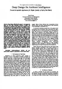
• Component structure: Each component can be contained within at most one component according to containment relationships in the physical world and cyberspace. It can move between components as a whole with all its inner components. When a component contains other components, the former component is called a parent and the latter children. When physical entities, spaces, and computing devices move from location to location in the physical world, the model detects their movements through location-sensing systems and changes the containment relationships of components corresponding to moving entities, their source, and destination. Each component is a virtual counterpart of its target in the world model and maintains the target’s attributes. Figure 1 shows the correlation between spaces and entities in the physical world and their counterpart components. The model also offers at least two basic events, entering and leaving, which enable application-specific services to react to actions in the physical world. Readers may think that this hierarchical model is similar to the notion of hierarchical mobile agents presented in our previous paper [8]. However, that enabled a large-scale mobile applications to be composed from multiple mobile agents, whereas the present model is aimed at modeling the physical world. 3.2. Component The model is unique to existing location models because it not only maintains the location of physical entities, such as people and objects, but also the locations of computing devices and services in a unified manner. As we can see from Figure 2, components can be classified into three types. • Virtual counterpart Component (VCC) is a digital representation of a physical entity, such as a person or object, except for the computing device, or physical place, such as a building or room, • Proxy Component (PC) is a proxy component that bridges the model and computing device, and maintains a subtree of the model or executes services located in a VCC. • Service Component (SC) is software that defines application-specific services dependent on physical entities or places. For example, a car carries two people and moves from location to location with its occupants. The car is mapped into a VCC on the model and this contains two VCCs that correspond to the two people. The movement of the car is mapped into the VCC migration corresponding to the car from the VCC corresponding to the source to the VCC corresponding to the destination. Also, when a person has a computer for executing services, his
computer A
room 1
corelation PC (computer B)
SC (service)
VC (person) VC (room 2)
SC (service) PC (PDA)
VC (room 3)
PC (computer A) VC (room 1) VC (floor)
Figure 1: Rooms on floor in physical world and counterpart components in location model.
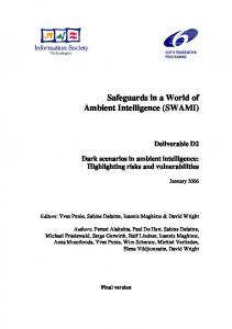
or her VCC has a PC, which represents the computer and runs SCs to define the services. Furthermore, the model also classifies PCs into three subtypes, PCM (PC for Model manager), PCS (PC for Service provider), and PCL (PC for Legacy device), according to the functions of the devices. Our model can be maintained by not only the server but also multiple computing devices in ubiquitous computing environments. The first component, i.e., PCM, is a proxy of a computing device maintaining a subtree of the components in the model (Figure 2(a)). It attaches the subtree of its target device to a tree maintained by another computing device. Some computing devices can provide runtime systems to execute services defined as SCs. The second component, i.e., PCS, is a proxy of the computing device that can execute SCs (Figure 2(b)). If such a device is in a space, its proxy is contained by the VCC corresponding to the space. When a PCS receives SCs, it forwards these to the device that it refers to. The third component, called PCL (PC for Legacy device), is a proxy of the computing device that cannot execute SCs (Figure 2(c)). If such a device is in a space, its proxy is contained by the VCC corresponding to the space and it communicates with the device through the device’s favorite protocols. For example, a television, which does not have any computing capabilities, can have an SC in the VCC corresponding to the physical space that it is contained in and can be controlled in, and the SC can send infrared signals to it. A computing device can have different PCs whereby it can provide computing capabilities to them.
4. Design and Implementation To evaluate the model described in this section, we implemented a prototype system that was built it. The model itself is independent of programming languages but the current implementation
(a)
VCC
VCC VCC
bilateral link
computer 1 for managing space model 1
VCC
VCC
VCC
VCC
PC
mount
VCC
computer 2 for managing space model 2
(b)
SC
forwarding SC
SC
migration
PC
computer 1 for managing space model 1
SC
VCC VCC
computer 2 for managing space model 2
(c)
interaction
SC
communcation
black box computer 1 for executing its program
VCC
PC VCC
computer 2 for managing space model 2
Figure 2: Three types of proxy components
uses Java (J2SE or later versions) as an implementation language for components. 4.1. Virtual Counterpart Component (VCC) In the current implementation, each VCC is defined as a subclass of abstract class VirtualComponent, which has some built-in methods that are used to control its mobility and lifecycle. It is bound to at least one entity or space in the physical world and is located at the VCC that spatially contains the entity or place. class VirtualComponent extends Component { void setIdentity(String name) { ... } void setAttribute(String attribute, String value){ ... } String getAttribute(String attribute) {..} ComponentInfo getParentComponent() { ... } ComponentInfo[] getChildren() { ... } ServiceInfo[] getParentServices( String name) { ... } ServiceInfo[] getAncestorServices( String name) { ... } Object execService(ServiceInfo si, Message m) throws NoSuchServiceException { ... } .... }
By invoking setIdentity, a VCC can assign the symbolic name of the physical entity or space that it represents. For example, a VCC refers to the coverage area of an RFID reader and it has the identify of the reader. By invoking setAttribute, a VCC can record attributes about its entity or space inside it. e.g., owner and size. Each VCC can provide its inner components with services defined inside it as a service provider. Furthermore, it allows them to access the service methods provided by the SCs contained within it. When a component invokes getAncestorServices with a keyword, the runtime system searches suitable services in the direction of the route of a component tree structure from the component’s parent. If ancestral components or ancestral component SCs have service
methods that match the keyword, it returns a list of suitable service methods to the component. The component can access one of the methods by invoking execServices with an instance of the Message class, which can specify the kind of message, arbitrary objects as arguments, and deadlines for timeout exceptions. Some readers may feel that such a keyword-based search for services may be too simple. However, the model itself supports a lightweight mechanism for discovering services because it needs to be available for less powerful computing devices. The keyword-based mechanism is lightweight and useful in operating many applications, including the examples presented in Section 5, because these need a mechanism for enabling components to detect suitable services from their ancestor components. Furthermore, our model can easily be extended by defining subclasses for components. For example, the model allows services to be specified with their attributes in XML-form and detected according to these attributes. 4.2. Proxy Component (PC) PCs are key elements in the model. According to the types of computing devices, PCs can be classified into three classes, i.e., PCM, PCS, and PCL. Note that a computing device can have different PCs. 4.2.1. Proxy Component for Model Manager (PCM) Each component hierarchy is maintained as a tree structure where each node contains a component and its attributes in PCMs. Each node in a tree has attributes that specify its meta information, e.g., its name, identifier, category, owner, and real time, in XML-based notations. Each PCM attaches a subtree maintained by its target computing device to a tree maintained by another computing device. It forwards its visiting components or control messages to its target device from the device that it is located at, and vice versa, by using the component migration mechanism. For example, when it receives SCs and VCCs, it transmits its target device to deploy them at appropriate nodes of the subtree maintained by the device. The containment relationship between components in this model can be explicitly configured by users by deploying PCMs at another PCM. 4.2.2. Proxy Component for Service Provider (PCS) Each PCS is a representation of the computing device that can execute SCs. It automatically forwards its visiting SCs to its target device by using the component migration mechanism. Each SC can have one or more activities that are implemented by using the Java thread library. PCSs can control all SCs inside them under the protection of Java’s security manager. Furthermore, PCSs maintain the life-cycle of SCs: i.e., initialization, execution, suspension, and termination. When the life-cycle state of an SC is changed, the runtime system issues certain events to the SC and the SC’s descendent components (and the SC’s parent component). 4.2.3. Proxy Component for Legacy Device (PCL) Each PCL supports a legacy computing device that cannot execute SCs due to limitations with its computational resources. It is located at a VCC corresponding to the space that contains its target device. It establishes communication with its target device through its favorite approach, e.g., serial communications and infrared signals. For example, a television, which does not have any computing capabilities, can have an SC in the VCC
corresponding to the physical space that it is contained in and can be controlled in, and the SC can send infrared signals to it. 4.3. Service Component (SC) Many computing devices in ubiquitous computing environments only have a small amount of memory and slower processors. They cannot always support all services. Here, we introduce an approach to dynamically installing upgraded software that is immediately required in computing devices that may be running. SCs are mobile software that can travel from computing device to computing device achieved by using mobile agent technology. The current implementation assumes SCs to be Java programs. They can be dynamically deployed at computing devices. Each SC consists of service methods and is defined as a subclass of the abstract class ServiceComponent. Most serializable JavaBeans can be used as SCs. class ServiceComponent extends Component { void setName(String name) Host getCurrentHost() { ... } void follow(ComponentID id) throws NoComponentException { ... } void setComponentProfile( ComponentProfile cpf) { ... } Hosts[] getNeighboringHosts() { ... } Host[] getCandidateHosts(Host[] hosts) {..} .... }
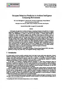
4.4.2. Component Migration Component migration in a component hierarchy is done merely as a transformation of the tree structure of the hierarchy (Figure 3). When a component is moved to another component, a subtree, whose root corresponds to the component and branches correspond to its descendent component is moved to a subtree representing the destination. When a component is transferred over a network, the runtime system stores the state and the code of the component, including the components embedded within it, into a bit-stream formed in Java’s JAR file format that can support digital signatures for authentication. The system has a built-in mechanism for transmitting the bit-stream over the network through an extension of the HTTP protocol. The current system basically uses the Java object serialization package for marshaling components. The package does not support the stack frames of threads being captured. Instead, when a component is serialized, the system propagates certain events within its embedded components to instruct the agent to stop its active threads. step 2
step 1 Component D
migration Component F Component E
Component B
Component F Component E
Component D
Component C
Component B
Component A
Component C Component A
mapping
migration Component F
Component F
When an SC migrates to another computer, not only the program code but also its state are transferred to the destination. For example, if an SC is included in a VCC corresponding to a user, when the user moves to another location, it is migrated with the VCC to a VCC corresponding to the location. The model allows each SC to specify the minimal (and preferable) capabilities of PCSs that it may visit, e.g., vendor and model class of the device (i.e, PC, PDA, or phone), its screen size, number of colors, CPU, memory, input devices, and secondary storage, in CC/PP (composite capability/preference profiles) form [14]. Each SC can register such capabilities by invoking setComponentProfile(). 4.4. Component Management System Components can be dynamically deployed at computing devices according to changes in the locations of physical entities, spaces, and other components. 4.4.1. Distributed Model Management Our model can be maintained not only by centralized database servers but also by more than one computing device. The key idea is to enable the model to manage the computing devices that maintain it. This is because a PCM is a proxy for the subtree that its target computing device maintains and is located in the subtree that another computing device maintains. As a result, it can attach the former subtree to the latter. When it receives other components and control messages, it automatically forwards the visiting components or messages to the device that it refers to (and vice versa) by using a component migration mechanism, like PCSs. Therefore, even when the model consists of subtrees that multiple computing devices maintain, it can be treated as a single tree. Note that a computing device can maintain more than one subtree. Since the model does not distinguish between computing devices that maintain subtrees and computing devices that can execute services, the former can be the latter.
Component D
Component D
Component E
Component E
migration Component B
Component C
Component A
Component B
Component C
Component A
Figure 3: Component containment and migration
4.4.3. Inter-component Management As ubiquitous computers have limited computational resources for various services, services must not be bound to them but should run on computers that can satisfy what the services require. For example, a mobile user may also want to constantly change the computers with which he or she interacts. That is, services should move from computer to computer to follow the user. However, when SCs follows the migration of the VCC corresponding to the user, the destination PC of the VCC cannot always satisfy the requirements of the SCs. To solve this, the model enables each SC to explicitly specify a policy for component migration, called a hook.1 The current implementation provides two types of hooks. Moreover, each reference defines two migration policies for two components, an attachment hook and follow hook, as follows: • When an SC declares an attachment hook for a VCC, if the VCC migrates to another VCC, which can satisfy the requirements of the SC and can execute the SC, the VCC instructs the SC to migrate to the destination VCC. • When an SC declares a follow hook for a VCC, if the VCC migrates to another VCC, the VCC instructs the SC to migrate to a nearby PC, where the PC is contained by the destination VCC that can satisfy the requirements of the SC and can execute the SC. 1 The
policy mechanism was presented in our previous paper [11].
When there is no suitable destination, which can satisfy the requirements of the SC, the model informs what capabilities are required to the PCs within the destination VCC of the moving VCC, because each SC is an autonomous entity so that it can migrate to another computer under its own control. 4.4.4. Location-sensor Management The model offers an automatic configuration mechanism to deploy components by using location-sensing systems. To bridge PCMs and location-sensors, the model introduces locationmanagement systems, called LCMs, outside the PCMs. Each LCM manages location sensors and maintains a database where it stores bindings between references of physical entities in sensors, e.g., the identifiers of RFID tags attached to the entities and the identifiers of VCCs corresponding to the entities. Each LCM is responsible for discovering VCCs bound to entities or PCs bound to computing devices within the coverage areas of the sensors that it manages. When an entity (or device) attached to an RFID-tag and an LCM detect the presence of the entity (or device) within the coverage area of an RFID reader managed by the LCM, the LCM searches its database for VCCs (or PCs) bound to the entity (or device) and informs computing devices that maintain the VCCs (or PCs) about the VCC corresponding to the reader. Then the VCCs (or PCs) migrate to the reader’s VCC. If the LCM’s database does not have any information about the the entity (or device), it multicasts query messages to other LCMs. If other LCMs have any information about the entity, the LCM creates a default VCC as a new entity. When the tag is attached to an unknown device that can maintain a subtree or execute SCs, the LCM instructs the VCC that contains the device to create a default PCM or PCS for the device.
has. 5.1. Follow-Me Applications Follow-me services are a typical application in ubiquitous computing environments. For example, Cambridge University’s Sentient Computing project [4] enabled applications to provide a location-aware platform using infrared-based or ultrasonicbased locating systems in a building.2 While a user is moving around, the platform can track his or her movement so that the graphical user interfaces of the user’s applications follow him or her. The model presented in this paper, on the other hand, enables moving users to be naturally represented independently of location-sensing systems. Unlike previous studies on the applications, it can also migrate such applications themselves to computers near the moving users. That is, the model provides each user with more than one VCC and can migrate this VCC to a VCC corresponding to the destination. For example, we developed a mobile window manager, which is a mobile agent, and could carry its desktop applications as a whole to another computer and control the size, position, and overlap in the windows of the applications. Using the model presented in this paper, the window manager could be easily and naturally implemented as a VCC bound to the user and desktop applications as SCs. They could be automatically moved to a VCC corresponding to the computer that was in the current location of the user by an LCM and could then continue processing at the computer, as outlined in Figure 4. step 2
step 1
component migration computer 2
computer 1
computer 1
computer 2
4.5. Current Status A prototype implementation of this model was built with Sun’s J2SE version 1.4 or later versions. It uses the Mobilespaces mobile agent system to provide mobile components and supports three commercial locating systems: Elpas’s system (infrared tag sensing system), RF Code’s Spider (active RF-tag system), and Alien Technology’s UHF-RFID tag (passive RFtag system). Although the current implementation was not built for performance, we measured the cost of migrating a 4-Kbyte component (zip-compressed) from the source to the destination recommended by an LSM over a network. The latency of component migration to the destination after the LSM had detected the presence of the component’s tag was 390 msec and the cost of component migration between two hosts over a TCP connection was 41 msec. This experiment was done with two computing devices that maintained the component tree, and source and destination computing devices, each of which was running on one of six computers (Pentium-M 1.6 GHz with Windows XP and J2SE ver. 5) connected through a Fast Ethernet network. We believe that this latency is acceptable for a location-aware system used in rooms or buildings.
5. Experience We gained a lot of experience with this model in developing and operating several typical applications for location-based and personalized services. Some of this has been presented in our previous papers [9, 10] independent of the model. Therefore, this section briefly discusses how the model represents and implements typical applications and what advantages the model
left RFIDreader
movement
right RFIDreader
left RFIDreader
right RFIDreader
Figure 4: Follow-me desktop applications between two computers.
5.2. Software Testing for Location-based Services It is difficult to test and develop software for location-based services, because the developer often has to carry the device to locations that his/her target portable device may have to move to and test whether the software, which is designed to run on the device, can execute appropriate services required at the location or not. We developed a novel approach to test location-aware software running on portable computing devices [9]. The approach involves a mobile emulator for portable computing devices that can travel between computers, and emulates the physical mobility and reconnection of a device to sub-networks using the logical mobility of the emulator between sub-networks. In this model, such an emulator can be naturally implemented as a PC, which provides application-level software, with the internal execution environments of its target portable computing devices and target software as SCs. As we can see from Figure 5 the emulator carries the software from a VCC that is running on a computer on the source-side sub-network to another VCC 2 The project does not report their model but their systems seem to model the position of people and things through lower-level results from underlying location-sensing systems.
that is running on another computer on the destination-side subnetwork. After migrating to the destination VCC, it enables its inner SCs to access network resources provided within the destination-side sub-network. Furthermore, SCs, which were successfully tested in the emulator, can run on target computing devices without modifying or recompiling the SCs. This is because this model provides a unified view of computing devices and software and enables SCs to be executed in both VCCs and PCs. We developed an extended system for the approach with the model. location-dependent services in source
location-dependent services in destination migration migration
computer for storing services VC (source)
SC-based emulator server for storing idle services VC (destination)
Figure 5: Testing location-aware map-viewer service.
6. Conclusion We presented a location model to develop and manage contextaware services, e.g., location-aware and personalized information services, in ubiquitous computing environments. Like existing related models, it can be dynamically organized like a tree based on geographical containment, such as that in a userroom-floor-building hierarchy and each node in the tree can be constructed as an executable software component. It also has several advantages in that it can be used to model not only stationary but also moving spaces, e.g., cars. It enables contextaware services to be managed without databases and can be managed with multiple computers. It can provide a unified view of the locations of not only physical entities and spaces, including users and objects, but also computing devices and services. We also designed and implemented a prototype system based on the model and demonstrated its effectiveness in several practical applications. Finally, we would like to point out further issues that need to be resolved. Since the model presented in this paper is general-purpose, we need to apply it to a variety of services in future work. The prototype implementation presented in this paper is built on Java but the model itself is independent of programming languages. We are interested in extending the model to other languages. We plan to design more elegant and flexible APIs for the model by incorporating existing spatial database technologies.
7. References [1] M. Bauer, C. Becker, and K. Rothermel Location Models from the Perspective of Context-Aware Applications and Mobile Ad Hoc Networks, Personal and Ubiquitous Computing, vol. 6, Issue 5-6, pp. 322-328, Springer, 2002. [2] M. Beigl, T. Zimmer, C. Decker, A Location Model for Communicating and Processing of Context, Personal and Ubiquitous Computing, vol. 6 Issue 5-6, pp. 341-357, Springer, 2002 [3] K. Cheverst, N. Davis, K. Mitchell, and A. Friday, Experiences of Developing and Deploying a Context-Aware
Tourist Guide: The GUIDE Project, Proceedings of Conference on Mobile Computing and Networking (MOBICOM’2000), pp. 20-31, ACM Press, 2000. [4] A. Harter, A. Hopper, P. Steggeles, A. Ward, and P. Webster, The Anatomy of a Context-Aware Application, Proceedings of Conference on Mobile Computing and Networking (MOBICOM’99), pp. 59-68, ACM Press, 1999. [5] F. Hohl, U. Kubach, A. Leonhardi, K. Rothermel, and M. Schwehm, Next Century Challenges: Nexus - An Open Global Infrastructure for Spatial-Aware Applications, Proceedings of Conference on Mobile Computing and Networking (MOBICOM’99), pp. 249-255, ACM Press, 1999). [6] T. Kindberg, et al, People, Places, Things: Web Presence for the Real World, Technical Report HPL-2000-16, Internet and Mobile Systems Laboratory, HP Laboratories, 2000. [7] K. Romer, T. Schoch, F. Mattern, and T. Dubendorfer, Smart Identification Frameworks for Ubiquitous Computing Applications, IEEE International Conference on Pervasive Computing and Communications (PerCom’03), pp.253-262, IEEE Computer Society, March 2003. [8] I. Satoh, MobileSpaces: A Framework for Building Adaptive Distributed Applications Using a Hierarchical Mobile Agent System, Proceedings of IEEE International Conference on Distributed Computing Systems (ICDCS’2000), pp.161-168, April 2000. [9] I. Satoh, A Testing Framework for Mobile Computing Software, IEEE Transactions on Software Engineering, vol. 29, no. 12, pp.1112-1121, December 2003. [10] I. Satoh, Linking Physical Worlds to Logical Worlds with Mobile Agents, Proceedings of International Conference on Mobile Data Management (MDM’2004), IEEE Computer Society, January 2004. [11] I. Satoh, Dynamic Deployment of Pervasive Services, to appear in IEEE International Conference on Pervasive Services (ICPS’2005), IEEE Computer Society, July 2005. [12] I. Satoh, Dynamic Federation of Partitioned Applications in Ubiquitous Computing Environments, to appear in Proceedings of 3rd International Conference on Pervasive Computing and Communications (PerCom’2005), IEEE Computer Society, March 2005. [13] R. Want, B. Schilit, A. Norman, R. Gold, D. Goldberg, K. Petersen, J. Ellis, and M. Weiser, An Overview of the Parctab Ubiquitous Computing Experiment, IEEE Personal Communications, Vol 2. No.6, pp28-43, December 1995. [14] World Wide Web Consortium (W3C), Composite Capability/Preference Profiles (CC/PP), http://www.w3.org/ TR/NOTE-CCPP, 1999.