This article has been accepted for publication in a future issue of this journal, but has not been fully edited. Content may change prior to final publication. Citation information: DOI 10.1109/ACCESS.2016.2633285, IEEE Access 1
A Low Complexity Iterative Channel Estimation and Decoding Receiver Based on Reed-Solomon PTA O.O Ogundile and D.J.J Versfeld, Member IEEE
Abstract—A low complexity iterative channel estimation and Reed-Solomon (RS) decoding receiver is developed. The joint channel estimation and decoding receiver is based on the Linear Minimum Mean Square Error (LMMSE) channel estimation technique and the recently proposed RS Parity-check Transformation Algorithm (PTA). A key feature of this joint receiver is the simple symbol remapping process used to refine the initial LMMSE estimate of the channel after each iterative RS-PTA decoding. The performance of the joint iterative receiver is compiled through computer simulation assuming a rectangular M -ary Quadrature Amplitude Modulation (M -QAM) as the underlying modulation scheme. Simulation results show significant Symbol Error Rate (SER) improvement in the iterative receiver in comparison with the receiver without iterative feedback. Besides, the RS-PTA iterative receiver outperforms the recently proposed RS Koetter and Vardy (RS-KV) iterative receiver structure both in terms of the SER performance and the computational time complexity. Of particular interest, results verify that the computational time complexity of the RS-PTA iterative receiver can be reduced without compromising the SER performance of the receiver. Index Terms—Channel estimation, CSI, fading channels, iterative receivers, LMMSE, RS-KV, RS-PTA.
1. I NTRODUCTION The advantages and applications of iterative channel estimation and decoding receivers have been extensively investigated in literature [1]–[3]. The advancement in wireless communication applications encourage the use of iterative channel estimation and decoding receivers because of the varying nature of the Rayleigh fading channel. Traditionally, in iterative receiver structures, the initial Channel State Information (CSI) are computed using the properties of the known pilot symbols. The quality of the CSI is improved after each iterative decoding using the feedback information from the decoder. Different iterative channel estimation and decoding receivers have been proposed over the years, where the focus of these receiver designs have been to deliver efficient and reliable data transmission over fading channels at low complexity. Most techniques on iterative channel estimation and decoding receivers use Turbo and Low Density Parity Check (LDPC) codes as the Forward Error Correction (FEC) scheme in the receiver structure [1], [2], [4]–[6]. In this paper, attention is centred on Reed-Solomon (RS) codes as the underlying FEC scheme in the receiver structure. In addition, this paper focuses on symbol-wise RS decoders. The authors are with the School of Electrical and Information Engineering, University of the Witwatersrand, Private Bag 3, Wits 2050, Johannesburg, South Africa. Emails:
[email protected] and
[email protected]
The RS codes discovered in [7], have been shown to meet the singleton bound, which makes the code maximum distance separable [8], [9]. Efficient soft decision RS decoding algorithms include [14]–[17]; however, [16], [17] are bit-wise based RS decoding algorithms. These RS soft decision decoding algorithms have been shown to perform beyond the conventional RS hard decision decoding algorithms such as [10]–[13]. Notwithstanding, the performance of RS codes and other FEC schemes degrade over Rayleigh fading channels due to the varying nature of the channel. This therefore motivated the use of FEC decoding schemes in the form of joint iterative channel estimation and decoding receivers. We provided a survey in [3] and proposed the first joint iterative channel estimation and RS decoding receiver using the Koetter and Vardy (RS-KV) soft decision decoder [15] as the FEC scheme in the receiver structure. The importance of deploying RS codes in an iterative receiver structure was emphasized in [3]. Additionally, we divulged in [3] that RS codes are suitable in iterative receiver structures as in the case with Turbo and LDPC codes. The main drawback of the joint iterative receiver structure in [3] is the computational delay and time complexity of the receiver, majorly due to the RS-KV algorithm used in the receiver structure. The RS-KV decoder applied to the Guruswami and Sudan algorithm (GS) [18] standing alone can provide a practical O(M 2 n2 I 4 ) complexity to the receiver structure, where n is the codeword length and I is the adjustable interpolation multiplicity specified in the GS algorithm1 [19]. In this regard, we propose a low complexity iterative channel estimation and decoding receiver structure based on the RS Parity-check Transformation Algorithm (RS-PTA)2 . This proposed RS-PTA iterative receiver structure is a low complexity and high performance efficient modification of the RS-KV iterative receiver structure that was proposed in [3]. The paper adopts M -ary Quadrature Amplitude Modulation (M -QAM) systems as the underlying modulation scheme, where M =16. The CSI is derived using the Pilot Symbol Assisted Modulation (PSAM) Linear Minimum Mean Square Error (LMMSE) estimator [1], [20]. More so, we assume a flat Rayleigh fading channel with normalized Doppler fre1 Although the RS-KV decoder do not impose the same interpolation multiplicity I to all the interpolation points, each of the M × n points can have a different multiplicity. 2 Note in passing that we developed the RS-PTA decoder [14] used in this proposed RS iterative receiver structure.
2169-3536 (c) 2016 IEEE. Translations and content mining are permitted for academic research only. Personal use is also permitted, but republication/redistribution requires IEEE permission. See http://www.ieee.org/publications_standards/publications/rights/index.html for more information.
This article has been accepted for publication in a future issue of this journal, but has not been fully edited. Content may change prior to final publication. Citation information: DOI 10.1109/ACCESS.2016.2633285, IEEE Access
Input symbol
RS encode
16-QAM mapping
Pilot insertion
Channel LMMSE (pilot removal)
R-matrix
RS-PTA decode
Output symbol
Fig. 1: RS-PTA coded 16-QAM transceiver system.
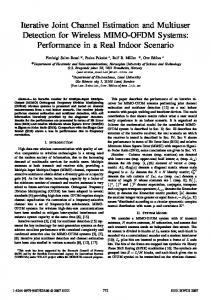
The results in Fig. 2 are compiled from a simple RSPTA coded 16-QAM system set-up as shown in Fig. 13 . From Fig. 2, it can be seen that the SER for perfect CSI (δ=0.001) is 10−2 at a SNR of approximately 22dB. Perfect CSI means that the CSI is known and do not need to be estimated. On the other hand, the SER degrades to 10−1 when the CSI is estimated using LMMSE estimator with known pilot symbols. This discrepancy is due to the varying nature of the Rayleigh fading channel which cannot be easily tracked, most especially at high Fd T . This in summary plummets the performance of the RS-PTA decoder and all FEC decoders. One way of solving this problem; that is, improving the SER performance of this RS-PTA over Rayleigh fading channels is by iteratively combining the RS-PTA decoder with an optimal channel estimation technique as proposed in this paper.
quency Fd T (where, Fd is the Doppler frequency and T is the symbol period). The Jakes’s isotropic scattering model [21] is deployed for the complex Rayleigh fading. Firstly, we show in Fig. 11, that the RS-PTA iterative receiver structure offers better Symbol Error Rate (SER) performance as compared to RS-KV iterative receiver structure in [3]. Secondly, as expounded in [14], the RS-PTA is a much less computationally intensive decoding algorithm in comparison with the RS-KV algorithm. Consequently, it exhibits low computational delay and time complexity when deployed in a joint iterative receiver structure as shown in Table 1. Besides, the proposed RS-PTA iterative receiver structure showcases a simple symbol remapping technique in comparison with most iterative receiver structures found in the literature. Thus, the RS-PTA iterative receiver structure can be deployed in real time communication systems.
B. Contribution and Related Work A. Problem Statement
As earlier mentioned, [3] proposed the first symbol-wise RS iterative channel estimation receiver using the RS-KV decoder. The iterative receiver proposed in [3] exhibits high computational delay and time complexity largely due to the RS-KV decoder. Thus, the RS-PTA iterative channel estimation receiver is proposed in this paper as an alternative to the work in [3]. The proposed iterative channel estimation and RS-PTA decoder exhibits low computational delay and time complexity, and a better SER performance in comparison to the work in [3] as presented in Section 4-B. The RS codes are deployed in wireless communication applications such as LTE (Long-Term Evolution), DVB (Digital Video Broadcasting), DAB (Digital Audio Broadcasting), and in long distance satellite communications. Also, the use of RS code in DAB and DVB applications is recommended by the European Telecommunications Standard Institute (ETSI) [22], [23]. Furthermore, because RS codes are capable of correcting both burst and random errors, the Consultative Committee for Space Data Systems (CCSDS) suggest the adoption of RS codes in data link [24], [25]. Therefore, the proposed RS-PTA iterative receiver can be used in these applications because they require efficient and low complexity channel estimation and RS decoding scheme over Rayleigh fading channels. Note that the primary purpose of this paper is not to compare between codes (RS codes, Turbo codes or LDPC codes), rather, the proposal of a less complex and performance efficient iterative receiver structure based on Reed-Solomon codes and a fair comparison with existing RS iterative receiver structure.
The PTA [14] was proposed as a soft decision decoding FEC scheme for RS codes. The PTA is a symbol-wise RS soft decoder that iteratively transforms the parity-check matrix in order to perform a syndrome check. With each iteration, the RS-PTA fine-tune the derived soft reliability information from the channel output based on some rules. The RS-PTA has an adjustable decimal parameter δ which specifies the decoding SER versus Signal-to-Noise Ratio (SNR) performance, and the decoding time complexity of the algorithm. In all cases, the smaller the degree of δ the better the SER performance of the RS-PTA, which in turns increase the decoding time complexity of the algorithm. For reference, see Fig. 2.
2
n = 15, k = 7, c = 1/10
0
10
−1
Symbol Error Rate
10
Perfect CSI, δ = 0.001 Perfect CSI, δ = 0.005 Perfect CSI, δ = 0.01 Perfect CSI, δ = 0.05 LMMSE estimate, δ = 0.001 LMMSE estimate, δ = 0.005 LMMSE estimate, δ = 0.01 LMMSE estimate, δ = 0.05
−2
10
−3
10
−4
10
5
10
15 SNR[dB]
20
25
The remainder of this paper is organised as follows. The discrete-time transmitter and channel model is described in Section 2. Section 3 explains the proposed RS-PTA iterative
30
Fig. 2: SER performance of the RS-PTA over flat Rayleigh fading channel, Fd T = 0.015.
3 The
2
blocks in Fig. 1 are explained in subsequent sections
2169-3536 (c) 2016 IEEE. Translations and content mining are permitted for academic research only. Personal use is also permitted, but republication/redistribution requires IEEE permission. See http://www.ieee.org/publications_standards/publications/rights/index.html for more information.
This article has been accepted for publication in a future issue of this journal, but has not been fully edited. Content may change prior to final publication. Citation information: DOI 10.1109/ACCESS.2016.2633285, IEEE Access
receiver structure in a block-wise fashion. Results with discernible comments are presented in Section 4. In particular, Section 4 presents a comparative SER simulation result and computational time complexity analysis between the RS-KV iterative receiver structure and this proposed RS-PTA iterative receiver structure. This paper is summarised with notable remarks in Section 5.
symbol. In order to derive the CSI (zu ) at the data symbol positions, this known properties of the pilot symbols are used. In Fig. 5, the known properties of the pilot symbols (that is, the CSI at the pilot symbol positions) are firstly used to derive the initial CSI at the data symbol positions. Afterwards, the pilot symbols are separated from the data symbols. Therefore, a soft reliability information matrix is initially derived from the data symbols. The initial soft reliability information is fed into the RS-PTA decoder which iteratively operate on this matrix to produce a final reliability information matrix. The output of the RS-PTA decoder (the final reliability information matrix) is simply remapped into symbols in order to finetune the initial CSI. The RS-PTA iterative receiver process is further explained as follows.
2. T RANSMITTER AND C HANNEL M ODEL Input g (n, k) gˆ symbol RS encode
16-QAM xu mapping
Pilot insertion p
xv
Fig. 3: Transmitter model of an RS coded 16-QAM system.
A. Initial LMMSE Estimate
Fig. 3 depicts the discrete-time transmitter model of an RS coded 16-QAM system. The generated input symbol g is encoded using an (n, k) RS code, where k is the length of the information symbol, and n is defined as above. The encoded symbol gˆ is mapped to rectangular 16-QAM (M =16) complex data symbols in which the in-phase and quadrature parts both assume values from a set (±1c, ±3c, .... ± (m − 1)c), where m is defined as M = m2 [26], [27]. In order to efficiently track the effect of the fading channel, pilot symbols p (p is the number of pilot symbols in each transmitted codeword n, in this case p = 5) are intermittently inserted to the mapped symbols xu as shown in Fig. 4. In this paper, we assumed that all the pilot symbols have uniform value. The pilot and data sequence x(n+p) is divided into frames of equal length FL (where FL =4) with the assumption that each frame starts with a pilot symbol. This frame structure is transmitted over a flat Rayleigh fading channel and it is contorted with Additive White Gaussian Noise (AWGN).
Given that the properties at the pilot symbol position only is defined as: yp = cxp zp + φp ,
The notation ψiu is derived using the Wiener-Hopf equation defined as [1], [20]: Cu = Aψu , (4) where A and Cu are the autocorrelation matrix and covariance vectors respectively defined as [1], [20]: h i h i A = E yp yp† and Cu = E zp∗ yp . (5) The sign † and ∗ denotes the conjugate transpose and the complex conjugate respectively. As a key note, ψu is interpolated to derive the CSI at the each data symbol position. See [1], [20] for straightforward derivations of the LMMSE estimator.
n+p Data symbol
Fig. 4: Transmitted data and pilot frame structure.
B. Initial R-matrix The noisy received data symbols (yv ) are firstly separated from the pilot symbols. Subsequently, we scaled the noisy received data symbols by the derived CSI (zu ) in order to obtained the scaled received symbols (yu ) as defined by: yv , u = 1, 2, . . . , n. (6) yu = zu Hence, the initial reliability matrix (R-matrix) is computed from the scaled received symbols (yu ) and the symbols in the output 16-QAM constellation (qu ) as [8], [26], [28]: ! √ − (yuin −quin )+(yuim −quim ) D = c. e , (7)
3. RS-PTA I TERATIVE R ECEIVER S TRUCTURE The proposed RS-PTA iterative receiver structure is as illustrated in Fig. 5. The input to the iterative receiver after down-converting and matched filtering is defined as: yv = cxv zv + φv ,
v = 1, 2, . . . , n,
(2)
where yp , xp , and φp are defined as above but in terms of the pilot symbols only. The initial CSI is derived using the optimal Linear Minimum Mean Square Error (LMMSE) estimator proposed in [1], [20]. Hence, the LMMSE estimate of the fading distortion at the data symbol positions is expressed as [1], [20]: zu = ψu† yp . (3)
FL =4
Pilot symbol
p = 1, . . . , 5,
(1)
where yv is the noisy received symbol, φv is the complex AWGN with variance σ 2 = No /2 (No is the noise power), c is a positive real number, and zv is the complex discrete-time zero mean Gaussian variable representing the fading distortion at both the data and pilot symbol positions. In practice, zv is only known at the pilot symbol positions by dividing the received pilot symbols with the known transmitted pilot
where qu = (quin , quim ) is the in-phase and quadrature parts of the symbols in the output 16-QAM constellation, and yu = 3
2169-3536 (c) 2016 IEEE. Translations and content mining are permitted for academic research only. Personal use is also permitted, but republication/redistribution requires IEEE permission. See http://www.ieee.org/publications_standards/publications/rights/index.html for more information.
This article has been accepted for publication in a future issue of this journal, but has not been fully edited. Content may change prior to final publication. Citation information: DOI 10.1109/ACCESS.2016.2633285, IEEE Access
Symbol remapping y¯u
Poilot insertion p
xpu Iterative LMMSE zµu
Initial LMMSE ziu
yv
Rf RS-PTA decoder
yu Initial R-matrix Ri yu
g¯
Output symbols
Ri
Fig. 5: RS-PTA iterative receiver structure. ¯ in such a way that H ¯ contains a partitioned transform to H identity matrix where the indices of the parity column vectors are equal to β, and indices of the unit column vectors at are equal to γ. Finally, the PTA decoder calculates the n − k ¯ This is simply achieved by parity check equations using H. performing a hard decision detection on Ri to obtain a receive ¯ w (syndrome vector r. Afterwards, its finds the dot product r· H ¯ w denotes the w-th row of H. ¯ If the result check), where H of the dot product is equal to zero, all the elements of Rib,e is incremented by δ. Otherwise, all the elements of Rib,e is decremented by δ, where e ∈ at ∪β and b such that Rib,e is the highest element in column Rie . Thus, if all the parity check equations are satisfied, the iterative process is stopped, else, the new decision matrix Rf is used as the input. The process is repeated until Rf seats an element −Rfϕ,θ . The sign ϕ and θ represents the row and column of Rf respectively. The decoded symbol g¯ is therefore obtained from the hard decoding decision of Rf by selecting the most reliable symbols in each column of Rf . However, for more reliable symbol decoding over fading channels, the entries of Rf are remapped into symbols in order to improve the quality of the previous CSI. Refer to [14] for mathematical expression of the PTA decoder.
(yuin , yuim ) is the in-phase and quadrature parts of the scaled received symbols. Literally, (7) measures the distance from yu to all the output 16-QAM constellation points qu to form the R-matrix (Ri ) defined as: α0,0 α0,1 α0,2 . . . α0,n−1 α1,0 α1,1 α1,2 . . . α1,n−1 Ri = α2,0 α2,1 α2,2 . . . α2,n−1 . (8) .. .. .. . . . . . . . . . αn,0 αn,1 αn,2 . . . αn,n−1 The notation αn,n−1 is the reliability value denoting the likelihood of receiving a QAM symbol. Also, the entries of Ri are normalized and quantized to log2 (n + 1) bits of precision. For a performance efficient way of obtaining (8), refer to [26]. This initial soft reliability information matrix (Ri ) is fed into the RS-PTA decoder. The RS-PTA decoder [14] iteratively fine-tunes Ri based on some rules (as briefly explained in Section 3-C) to output a final reliability information matrix (Rf ). C. RS-PTA Decoder As explained in Section 1, the RS-PTA decoder iteratively operate on the derived R-matrix (Ri ) to produce a final Rmatrix Rf defined as: 0 0 0 0 α0,0 α0,1 α0,2 . . . α0,n−1 0 0 0 α0 1,0 α1,1 α1,2 . . . α1,n−1 0 0 0 0 α α2,1 α2,2 . . . α2,n−1 , Rf = (9) 2,0 .. .. .. .. .. . . . . . 0
αn,0
0
αn,1
0
αn,2
D. Symbol Remapping The output of the RS-PTA decoder (Rf ) prior to the hard decoding decisions, is simply remapped into symbols. This is performed by taking the mean of the elements in Rf over all the output 16-QAM constellation points qu as defined by (10): y¯uj =
0
. . . αn,n−1
n+1 X
qu Rfl,j ,
(10)
l=1
where l and j denotes the row and column of Rf respectively. The remapped symbols y¯u are subsequently fused with the pilot symbols in preparation for the next iterative estimate. Key remark, the RS-PTA iterative receiver structure do not require the Log-Likelihood Ratio (LLR) and the code bit probability calculation steps to derive the a priori information which is used in the symbol remapping process. Accordingly, the symbol remapping process of the RS-PTA iterative receiver
where Rf and Ri are of the same dimension. To obtain (9), the PTA decoder [14] firstly finds the k most reliable symbols from each column of Ri (in this case, we select the symbol with the highest reliability value). The indices of these k reliable symbols are denoted as β while the indices of the n − k remaining symbols are denoted as γ. Subsequently, the systematic parity check equation H is 4
2169-3536 (c) 2016 IEEE. Translations and content mining are permitted for academic research only. Personal use is also permitted, but republication/redistribution requires IEEE permission. See http://www.ieee.org/publications_standards/publications/rights/index.html for more information.
This article has been accepted for publication in a future issue of this journal, but has not been fully edited. Content may change prior to final publication. Citation information: DOI 10.1109/ACCESS.2016.2633285, IEEE Access
structure is far much less time complex in comparison with most iterative receiver structures in the literature. For more details on the LLR and the code bit probability calculation steps of iterative receiver structures, see references [2], [5], [6].
−1
Symbol Error Rate
10
E. Iterative LMMSE Estimate The iterative CSI estimate is derived using a similar approach as the initial CSI estimate. Thus, it is derived as: zµu = ψµ† u yu ,
n = 15, k = 7, c2 = 1/10
0
10
(11)
−2
10
Perfect CSI No-feedback Feedback, µ = 1 Feedback, µ = 2 Feedback, µ = 3 Feedback, µ = 4 Feedback, µ = 5
−3
10
where µ represents the number of iterative estimates, and yu is defined as: yu = cxpu zu + φu . (12)
−4
10
The combination of the remapped symbol y¯u and the pilot symbols is denoted as xpu . Moreover, the autocorrelation matrix A and the covariance vector are defined in terms of the received data symbols as: h i h i A = E yu yu† and Cu = E zu∗ yu . (13)
5
10
15 SNR[dB]
20
25
30
Fig. 6: SER performance of the RS-PTA iterative receiver structure for δ = 0.001, Fd T = 0.015. n = 15, k = 7, c2 = 1/10
10 0
The iterative process continues until the set number of iterative estimates is reached. Thus, we summarise the RS-PTA iterative receiver structure with the following algorithm. Symbol Error Rate
10 -1
Algorithm 1: RS-PTA iterative receiver structure Input: RS-PTA parameters, yv , p, µ. Output: Decoded vector g¯. derive: yu , zu , Ri ; repeat RS-PTA, Rf ; µ = false; repeat derive: y¯u , xpu , zµu , Ri ; RS-PTA, Rf ; until µ = true; until µ= true; Rf =¯ g
10 -2 Perfect CSI No-feedback Feedback, µ = 1 Feedback, µ = 2 Feedback, µ = 3 Feedback, µ = 4 Feedback, µ = 5
10 -3
10 -4
5
10
15
20
25
30
SNR[dB]
Fig. 7: SER performance of the RS-PTA iterative receiver structure for δ = 0.005, Fd T = 0.015.
respectively. The figures compare the SER performance of the iterative receiver assuming perfect CSI (that is, we assume that the CSI is known and does not need to be estimated with pilot symbols), the SER performance using pilot symbols without feedback, and the SER performance using pilots symbol with feedback. From the figures, it is observable that the RS-PTA iterative receiver structure exhibits good SER performance improvement in comparison with the RS-PTA receiver without feedback. Also, note that µ is set to 5 in the simulation set-up because we observed that the iterative channel estimates converge at µ = 5 for δ = 0.001 and δ = 0.005. In Fig. 9, there is no significant SER performance gain as µ increases to µ=6. However, this convergence condition is only investigated for δ = 0.001 and δ = 0.005. The value of µ might vary as δ decreases because the smaller the value of δ, the better the SER performance of the RS-PTA decoder.
4. P ERFORMANCE A NALAYSIS A. Performance Comparison of the RS-PTA Iterative Receiver Structure for Different δs In this Section, the computer simulation results of the RS-PTA receiver without feedback (Fig. 5 without the dashed lines, or Fig. 1) and with feedback (Fig. 5 with the dashed lines) are presented for different adjustable decimal parameter δ. A low rate (15, 7) RS code is assumed in the computer simulation set-up. A rectangular 16-QAM constellation is used as the underlying modulation scheme over a flat Rayleigh fading channel with normalized Doppler frequency Fd T = 0.015. In addition, a maximum number of iterative channel estimation µ = 5 is set. Fig. 6 and Fig. 7 verify the SER performance of the RSPTA iterative receiver structure for δ = 0.001 and δ = 0.005 5
2169-3536 (c) 2016 IEEE. Translations and content mining are permitted for academic research only. Personal use is also permitted, but republication/redistribution requires IEEE permission. See http://www.ieee.org/publications_standards/publications/rights/index.html for more information.
This article has been accepted for publication in a future issue of this journal, but has not been fully edited. Content may change prior to final publication. Citation information: DOI 10.1109/ACCESS.2016.2633285, IEEE Access
A priori information derivation
Symbol remapping
Decision directed process
Iterative LMMSE RS-KV decoder
R-matrix received symbol
Output symbol
Initial LMMSE Fig. 8: RS-KV iterative receiver structure.
for adjustable decimal parameters δ = 0.001 and δ = 0.005. Clearly, both δs offer similar SER performance as µ increases. Thus, we note that it is possible to reduce the degree of δ in order for the receiver to evince a moderate time complexity level while maintaining a comparable SER performance with δs of the same decimal digit. To buttress, as expounded in [14], a δ = 0.001 exhibits more than four times the decoding time complexity of δ = 0.005. Consequently, this means we can greatly reduce the computational time complexity of the RS-PTA iterative receiver by selecting a higher δ without compromising the SER performance of receiver.
n = 15, k = 7, c2 = 1/10
10 0
Symbol Error Rate
10 -1
10 -2 Perfect CSI No-feedback Feedback, µ = 1 Feedback, µ = 2 Feedback, µ = 3 Feedback, µ = 4 Feedback, µ = 5 Feedback, µ = 6
10 -3
n = 15, k = 7, c2 = 1/10
10 0 10 -4
5
10
15
20
25
30
SNR[dB] 10 -1
Symbol Error Rate
(a) δ = 0.001 2
n = 15, k = 7, c = 1/10
10 0
Symbol Error Rate
10 -1
10 -2 Perfect CSI, δ = 0.001 Perfect CSI, δ = 0.005 No-feedback, δ = 0.001 No-feedback, δ = 0.005 Feedback, µ = 4, δ = 0.001 Feedback, µ = 5, δ = 0.001 Feedback, µ = 4, δ = 0.005 Feedback, µ = 5, δ = 0.005
10 -3 10 -2 Perfect CSI No-feedback Feedback, µ = 1 Feedback, µ = 2 Feedback, µ = 3 Feedback, µ = 4 Feedback, µ = 5 Feedback, µ = 6
10 -3
10 -4
5
10
10 -4
5
10
15
20
25
30
SNR[dB]
Fig. 10: SER performance comparison of the RS-PTA iterative receiver structure for δ = 0.005 and δ = 0.001, Fd T = 0.015. 15
20
25
30
SNR[dB]
(b) δ = 0.005
B. Performance Comparison of the RS-PTA and RS-KV Iterative Receiver Structures
Fig. 9: SER performance comparison of the RS-PTA iterative receiver structure for µ = 1, . . . , 6, Fd T = 0.015.
1) Computational Complexity Performance Analysis: Fig. 8 depicts the RS-KV iterative receiver structure proposed in [3]. In comparison with the RS-PTA iterative receiver structure in Fig. 5, the RS-KV iterative receiver structure require extra blocks such as the decision directed
Of particular interest, Fig. 10 shows the SER performance of the RS-PTA iterative receiver structure at µ = 4 and µ = 5 6
2169-3536 (c) 2016 IEEE. Translations and content mining are permitted for academic research only. Personal use is also permitted, but republication/redistribution requires IEEE permission. See http://www.ieee.org/publications_standards/publications/rights/index.html for more information.
This article has been accepted for publication in a future issue of this journal, but has not been fully edited. Content may change prior to final publication. Citation information: DOI 10.1109/ACCESS.2016.2633285, IEEE Access
TABLE 1: Computational complexity analysis per iteration Blocks Initial LMMSE Iterative LMMSE R-matrix Symbol remapping RS-PTA decoder RS-KV decoder Decision directed process A priori information derivation
RS-PTA Iterative Receiver O(n2 ) O(n2 ) O(M n) O(M n) O(M n + h(n2 + h + 1)) 0 0 0
M =16, n=15, k=7, I=1 225 225 240 240 2112 0 0 0
RS-KV Iterative Receiver O(n2 ) O(n2 ) O(M n) O(M n) 0 O(M 2 n2 I 4 ) O(n) O(M n)
M =16, n=15, k=7, I=1 225 225 240 240 0 57600 15 240
efficient alternative to the RS-KV iterative receiver structure when RS codes are deployed in joint iterative channel estimation and decoding receiver structures.
process block, and the a priori information derivation block to complete the iterative process. These additional blocks increase the computational time complexity of the RS-KV iterative receiver structure, most especially the a priori information derivation block. However, in order to reduce the computational time complexity incurred by the a priori information derivation block, we assume the Distance Metric (DM) a priori information derivation method proposed in [3]4 . Besides, the RS-KV decoder is more complex in comparison with the RS-PTA decoder as explained in [14]. Thus, the proposed RS-PTA iterative receiver structure is characterised to exhibit lower computational time complexity in comparison to the RS-KV iterative receiver structure. The computational time complexity of the RS-PTA and the RS-KV iterative receiver structures for each block is as shown in Table 1.
n = 15, k = 7, c2 = 1/10
0
10
−1
Symbol Error Rate
10
−2
10
PerfectPTA CSI, δ = 0.001 PerfectKV CSI, L = 4 No-feedbackPTA, δ = 0.001 No-feedbackKV, L = 4 FeedbackPTA, µ = 3, δ = 0.001 FeedbackKV, µ = 3, L = 4
−3
10
As presented in Table 1, the extra blocks in the RS-KV iterative receiver generates a minimum of O(M n) and O(n) additional computational time complexity in comparison to the RS-PTA iterative receiver. Furthermore, the RS-KV decoder experiences a higher complexity of O(M 2 n2 I 4 ) in comparison to the O(M n + h(n2 + h + 1)) complexity experienced by the RS-PTA decoder, where h = (n − k). For example, given M = 16, n = 15, k = 7, and I = 1, the RS-KV decoder will experienced a minimum of 57600 complexity compared to the 2112 complexity experienced by the RS-PTA decoder. Note that this example assumes I = 1. In real time RS-KV decoding, the value of I varies from one to infinity depending on the list size L used in the algorithm. From this analysis, it can be concluded that the RS-PTA iterative receiver structure exhibits lower computational time complexity in comparison to the RS-KV iterative receiver structure. 2) SER Performance Comparison: In terms of the SER performance of both iterative receiver structures, we assume the same computer simulation parameters as in Section 4-A. In the RS-KV iterative receiver structure, a list size L=4 is assumed in the RS-KV algorithm [15], and a maximum possible iterative estimate of µ = 3 is set. Note, as demonstrated in [3], the RS-KV iterative receiver structure converges after µ = 3 for a list size L=4. Fig. 11 verifies the SER performance of both iterative receiver structures. As shown in the figure, the RS-PTA iterative receiver structure outperforms the RSKV iterative receiver structure. This delineates the RS-PTA iterative receiver structure as a less complex and performance
−4
10
5
10
15 SNR[dB]
20
25
30
Fig. 11: SER performance comparison of the RS-PTA and RS-KV iterative receiver structures, Fd T = 0.015.
5. C ONCLUSION A joint iterative channel estimation and RS-PTA decoding receiver has been developed in this paper. The performance of the RS-PTA iterative receiver structure was compared with the RS-KV iterative receiver structure. Firstly, it was established that the RS-PTA iterative receiver structure outperforms the RS-KV iterative receiver structure as shown in Fig. 11. Secondly, we demonstrated that the RS-KV iterative receiver structure exhibits much higher computational time complexity in comparison with the RS-PTA iterative receiver structure as presented in Table 1. Finally, we revealed in Fig. 10 that the complexity of the RS-PTA iterative receiver structure can be reduced by increasing the adjustable decimal parameter δ without compromising the SER performance of the receiver. The results presented in this paper are shown for 16-QAM and (15,7) RS code but the proposed RS-PTA iterative receiver structure can be extended using higher QAM signal constellations (M ) and RS codes. ACKNOWLEDGEMENT The financial assistance of the National Research Foundation (NRF) of South Africa towards this research is hereby
4 The DM a priori information derivation method was proposed in [3] as a low complexity alternative to the LLR approach.
7
2169-3536 (c) 2016 IEEE. Translations and content mining are permitted for academic research only. Personal use is also permitted, but republication/redistribution requires IEEE permission. See http://www.ieee.org/publications_standards/publications/rights/index.html for more information.
This article has been accepted for publication in a future issue of this journal, but has not been fully edited. Content may change prior to final publication. Citation information: DOI 10.1109/ACCESS.2016.2633285, IEEE Access
acknowledged. Opinions expressed and conclusions arrived at, are those of the authors and are not necessarily to be attributed to the NRF. The financial support of the Centre for Telecommunication Access and Services (CeTAS), the University of the Witwatersrand, Johannesburg, South Africa is also acknowledged.
[25] Y. Liu, et al., “Reed-Solomon Codes for Satellite Communications,” in Control, Automation and Systems Engineering, 2009. CASE 2009. IITA International Conference on, July 2009, pp. 246-249. [26] O. Ogundile and D. Versfeld, “Improved reliability information for rectangular 16-QAM over flat Rayleigh fading channels,” in Computational Science and Engineering (CSE), 2014 17th IEEE International Conference on, Dec 2014, pp. 345-349. [27] M. Simon and J. Smith, “Carrier Synchronization and Detection of QASK Signal Sets,” Communications, IEEE Transactions on, vol. 22, no. 2, pp. 98-106, Feb 1974. [28] W. Phoel, et al., “Frequency-hop spread spectrum with quadrature amplitude modulation and error-control coding.” in Military Communications Conference, 2004. MILCOM 2004. 2004 IEEE, vol. 2, Oct 2004, pp. 913-919 Vol. 2.
R EFERENCES [1] M. Valenti and B. Woerner, “Iterative channel estimation and decoding of pilot symbol assisted turbo codes over flat-fading channels,” Selected Areas in Communications, IEEE Journal on, vol. 19, no. 9, pp. 16971705, Sep 2001. [2] H. Niu and J, Ritcey, “Iterative channel estimation and decoding of pilot symbol assisted LDPC coded QAM over flat fading channels,” in Signals, Systems and Computers, 2004. Conference Record of the ThirtySeventh Asilomar Conference on, vol. 2, Nov 2003, pp. 2265-2269 Vol.2. [3] O. Ogundile, O. Oyerinde and D. Versfeld, “Decision directed iterative channel estimation and Reed-Solomon decoding over flat fading channels,” Communications, IET Vol. 9, no. 17 pp. 2077-2084, 2015. [4] T. Zemen, et al., “Improved channel estimation for iterative receivers,” in Global Telecommunications Conference, 2003. GLOBECOM ’03. IEEE, vol. 1, Dec 2003, pp. 257-261 Vol.1. [5] M.-K. Oh, et al., “Iterative Channel Estimation and LDPC Decoding With Encoded Pilots,” Vehicular Technology, IEEE Transactions on, vol. 57, no. 1, pp. 273-285, Jan 2008. [6] O. Oyerinde and S. Mneney, “Iterative receiver with soft-input-basedchannel estimation for orthogonal frequency division multiplexinginterleave division multiple access systems” Communications, IET, vol. 8, no. 14, pp. 2445-2457, Sept 2014. [7] I. G. Reed and G. Solomon, “Polynomial codes over certain finite fields,” J. Soc.Ind. Appl. Maths., 8:300-304, June 1960. [8] T. K. Moon, Error Correction Coding: Mathematical Methods and Algorithms. John Wiley & Sons, 2005. [9] S. Lin and D. J. Costello, Error Control Coding. 2nd ed. Prentice Hall, June 2005. [10] E. R. Berlekamp, Algebraic Coding Theory. New York: McGraw-Hill, Inc., 1968. [11] J. Massey, “Shift-register synthesis and bch decoding,” Information Theory, IEEE Transactions on, vol. 15, no. 1, pp. 122-127, Jan 1969. [12] R. Welch and R. Berlekamp, “Error Correction for Algebraic Block Codes,” Patent US 4 633 470, Dec. 30, 1986. [13] Y. Sugiyama, M. Kasahara, S. Hirasawa, and T. Namekawa, “A method for solving key equation for decoding goppa codes,” Information and Control, vol. 27, no. 1, pp. 87-99, 1975. [14] O. Ogundile, Y. Genga and D. Versfeld, “Symbol level iterative soft decision decoder for Reed-Solomon codes based on parity-check equations,” Electronics Letters, vol. 51, no. 17, pp. 1332-1333, 2015. [15] R. Koetter, and A. Vardy, “Algebraic soft-decision decoding of ReedSolomon codes,” Information Theory, IEEE Transactions on, vol. 49, no. 11, pp. 2809-2825, Nov 2003. [16] J. Jiang and K. Narayanan, “Iterative Soft-Input Soft-Output Decoding of Reed-Solomon Codes by Adapting the Parity-Check Matrix,” Information Theory, IEEE Transactions on, vol. 52, no. 8, pp. 37463756, Aug 2006. [17] O. Ur-rehman and N. Zivic, “Soft decision iterative error and erasure decoder for Reed-Solomon codes,” Communications, IET, vol. 8, no. 16, pp. 28632870, 2014. [18] V. Guruswami and M. Sudan, “Improved decoding of Reed-Solomon and algebraic-geometry codes,” Information Theory, IEEE Transactions on, vol. 45, no. 6, pp. 1757-1767, Sep 1999. [19] R. McEliece, “The Guruswami-Sudan Decoding Algorithm for Reed-Solomon Codes,” 16th April 2003. Available: http://www.(ee.caltech.edu/EE/Faculty/rjm/papers/RSD-JPL.pdf) [20] J. Cavers, “An analysis of pilot symbol assisted modulation for Rayleigh fading channels [mobile radio],” Vehicular Technology, IEEE Transactions on, vol. 40, no. 4, pp. 686-693, Nov 1991. [21] W. C. Jakes, Mobile microwave communication. New York: Wiley, 1974. [22] ETSI EN 300 744 V1.6.1 (2009-01), “DVB; Framing structure, channel coding, and modulation for digital terrestrial television”. [23] ETSI TS 102 563 V1.2.1 (2010-05), “DAB; Transport of AAC audio”. [24] CCSDS, “TM Synchronization and Channel Coding, Recommendation for Space Data Systems Standards.” CCSDS 131.0-B-1, Blue Book, Issue 1, September 2003.
8
2169-3536 (c) 2016 IEEE. Translations and content mining are permitted for academic research only. Personal use is also permitted, but republication/redistribution requires IEEE permission. See http://www.ieee.org/publications_standards/publications/rights/index.html for more information.