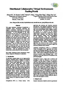
based on Mandriva 2007 which already comes with all the necessary packages required for Bluetooth. The setup uses an ASUS Bluetooth dongle (ASUS WL-.
A Low-cost, Linux-based Virtual Environment for Visualizing Vascular Structures Thomas Wischgoll Computer Science and Engineering, Wright State University
Abstract. The analysis of morphometric data of the vasculature of any organ requires appropriate visualization methods to be applied due to the vast number of vessels that can be present in such data. In addition, the geometric properties of vessel segments, i.e. being rather long and thin, can make it difficult to judge on relative position, despite depth cues such as proper lighting and shading of the vessels. Virtual environments that provide true 3-D visualization of the data can help enhance the visual perception. Ideally, the system should be relatively cost-effective. Hence, this paper describes a Linux-based virtual environment that utilizes a 50 inch plasma screen as its main display. The overall cost of the entire system is less than $3,500 which is considerably less than other commercial systems. The system was successfully used for visualizing vascular data sets providing true three-dimensional perception of the morphometric data.
1
Introduction
The analysis of spatial perfusion of any organ requires detailed morphometry on the geometry (diameters, lengths, number of vessels, etc.) and branching pattern (3-D angles, connectivity of vessels, etc.). Accurate methodologies for extracting this morphometry from volumetric data such as CT scans are becoming available nowadays [1]. The resolution of the scans can range from a little less than a millimeter down to just a few micrometers. Especially the latter can result in a vast number of vessel segments that can be extracted. Once extracted, this morphometry needs to be visualized in order to be analyzed properly. Based on a geometric reconstruction, an accurate visualization of the vasculature can be derived. Additional morphometric and statistical information can be incorporated into the visualization as well to enhance its informational value. However, is is often times difficult for a user to grasp the geometric configuration of the vasculature due to the high number of relatively thin and long objects presented by the individual vessel segments. Despite depth cues, such as proper lighting and shading of the vessels, it is often difficult to identify which vessel is in front and which one is in the back. A true 3-D visualization can help improve the visual perception. For example, Barco’s CADWall large projection display can be used which is capable of achieving stereoscopic rendering based on a polarized projection system. Figure 1 shows the visualization of a largescale vasculature including vessels from the most proximal vessel down to the capillary level.
2
Thomas Wischgoll
Fig. 1. Large-scale vasculature displayed on Barco’s CADWall in daytaOhio’s Appenzeller Visualization Laboratory at Wright State University.
Unfortunately, such a visualization system is prohibitive in most projects due to the high cost involved. Hence, there is a need for visualization systems that are capable of stereoscopic 3-D rendering at a significantly lower cost. Therefore, this paper describes a virtual environment that utilizes non-traditional display technology, which is capable of running any OpenGL-based application that uses quad-buffered rendering to create a virtual environment. The described system is based on Linux to provide a versatile operating system environment. The system is also technically capable of running a Windows-based operating system. Despite the 50 inch large plasma screen being used as its main display, the entire system is available for less than $3,500 which makes it a very low-cost, yet powerful visualization system. The structure of this article is as follows: initially, work related to this article is discussed. Subsequently, the low-cost, Linux-based virtual environment is described. Finally, conclusions and future work are presented.
2
Related Work
Virtual environments consist of two major components: first, display technology is required that allows a user to view in 3-D. Second, 3-D suitable input devices are required that do not bind the user to a certain location but instead allow for maximal freedom of movement of the user. For the display, there are typically a few technologies used. Head-mounted displays [2–4] consist of two
Lecture Notes in Computer Science
3
small screens mounted into a device that the user wears similar to a helmet such that the two screens are placed in front of the user’s eyes. Since the device is equipped with two individual screens, different images for the left and right eye can be easily displayed resulting in a 3-D effect experienced by the user. Typically, head-mounted displays have a resolution of only 800 by 600 pixels. Higher resolution head-mounted displays are available but significantly more expensive. One advantage of head-mounted displays is that some can be used as see-through devices for augmented reality systems [5]. Other display types [6–8] rely on glasses that hide the left image from the right eye and vice versa. This allows for a majority of displays to be used. Often times large projection walls are used which can be configured as a large wall-type display or a CAVE-like environment. Two different types of glasses are used in combination with these displays: active and passive. With passive glasses, polarization is used to ensure that the left image can only be seen by the left eye. For projection displays, two projectors are required where a polarization filter with different polarization is placed in front of each projector. The glasses then only let light pass with the correct polarization so that each eye only sees the image generated by one of the projectors. Nowadays, even some TFT-based monitors are becoming available that work with passive polarization glasses. Active stereo glasses work similar to TFT screens. Polarization filters can be activated that block all incoming light. The glasses then need to be synchronized with the display in such a way that ensures that the right image is only seen by the right eye. Typically, the system displays the images for the left and right eye in an alternating fashion and activates and deactivates the glasses for the left and right eye in the active stereo glasses accordingly. The advantage of this type of glasses is that they work with many different display types, such as projection displays, CRT screens, plasma displays. However, they do not work with TFT screens since they, too, use polarization filters for displaying an image so that the active stereo glasses filter out the light entirely all the time. Recently, auto-stereo displays were developed that are available at reasonable prices that can be used as displays for virtual environments. The advantage of this type of display is that it does not require the user to wear any glasses. Typically, barrier screens are used so that the light of half of the pixels gets directed more towards the left and the other half more towards the right. This way, one half of the pixels are only visible by one eye, whereas the other half can be seen only by the other eye, assuming the user is located somewhat centered in front of the display. As input devices, different wand or stylus devices are typically used. Often times, these are tracked either magnetically or optically to determine their position in 3-D space without the need of any cabling. More recently, standard game devices are utilized in virtual environments as well which are wirelessly connected to the computer. Wischgoll et al. [27] discuss the advantages of game controllers for navigation within virtual environments. Dang et al. [28] studied the usability of various interaction interfaces, such as voice, wand, pen, and sketch interfaces. Klochek et al. [29] introduced metrics for measuring the performance when using
4
Thomas Wischgoll
game controllers in three-dimensional environments. Wilson et al. [30] presented a technique for entering text using a standard game controller. Based on the previously described technology, a visualization of a model, such as a vasculature, can be presented to a user. In order to navigate through or around a displayed model, the camera location needs to be modified. In general, a camera model describes point of view, orientation, aperture angle, and direction and ratio of motion. A general system for camera movement based on the specification of position and orientation of the camera is presented in [9], while Gleicher et al. [10] choose an approach where through-the-lens control by solving for the time derivatives of the camera parameters is applied. The concept of walkthroughs in simulated virtual worlds using a flying metaphor has first been explored by Brooks [11]. Other commonly applied metaphors for navigation in virtual environments (VEs) such as ”eyeball in hand”, ”scene in hand” and ”flying vehicle control” were introduced by Ware and Osborne [12]. For camera and viewpoint navigation in virtual endoscopy systems, various aspects have to be considered. While free manual navigation in 3-D generates the problem of potential disorientation, proceeding automatically on a planned path is often too constraining. Planned navigation with automatic path planning by specifying camera parameters at key points has been explored for example by Nain et al. [13]. A mix between manual and planned navigation is called guided navigation. While Galyean [14] applies a river analogy for guided navigation in VEs, Hong et al. [15] among others utilize guided navigation paradigms with a combination of distance fields and kinematic rules for collision avoidance. Lorensen et al. [16] describe the use of a virtual endoscope for several types of data. Internal views of the data are explored by generating camera paths with key framing and robot path planning algorithms. Kaufman et al. [17] enhance their endoscopy system (volumetric environment) with automatic fly-through capability based on flight-path planning with the possibility of an interactive walk-through. Application areas for virtual endoscopy [18] are, for example, virtual colonoscopy [19], virtual angioscopy [20], and vessel visualization and exploration of the vasculature of the human liver [21]. The ViVa project [22] presents visualization solutions for virtual angioscopy and provides simple tools for measuring single distances inside the vessels. Sobel et al. [23] present a visionary system featuring novel visualizations and views of bifurcations. In addition, the blood flow is depicted by particles visualized as glyphs. Since the visualization aspect concentrates on non-photorealistic visualization techniques, no textures are used and no complex surface details are visible. This might be a restriction for physicians who are used to traditional (realistic) visualizations and real-life endoscopic images. Bajaj et al. [24] segment a CT scanned human heart using a seeded contour algorithm. The extracted parts are then aligned with a template to derive a patient-specific heart model. In addition, segmented vessels can then be further refined based on a NURBS interpolation to allow for an accurate simulation of blood flow in a patient-specific model as shown by Zhang et al. [25]. Simi-
Lecture Notes in Computer Science
5
larly, Forsberg et al. [26] introduced a virtual environment for exploring the flow through an artery.
3
A Linux-based Virtual Environment
Fig. 2. TriDef 3-D stereo glasses.
The system described in this paper uses a large-screen plasma display as the main screen for the virtual environment combined with shutter glasses. The shutter glasses used for the described system are TriDef’s 3-D Wireless Glasses. These glasses come with an infrared emitter to achieve flipping between the left and right eye. Figure 2 depicts the model used for the described system. The package also contains a software CD which only runs on Windows operating systems. Even though the emitter for the shutter glasses uses a regular DIN connector, it cannot be plugged into the port at the graphics card since a different protocol is used. Instead, the emitter needs to be plugged into the port at the back of the display screen. Accordingly, only screens that provide such a port can be used in this configuration. Various such screens are available from manufactures such as Mitsubishi and Samsung that are equipped with 3-D technology. The described setup uses the 50 inch plasma display Samsung P50A450. This plasma display has a resolution of 1360 by 768 pixels. Higher resolution rear-projection displays with full HD resolution of 1920 by 1080 are also available from Samsung that provide the necessary 3-D capabilities. The advantage of plasma displays over projectors is the higher durability, while still providing a large display surface. Typically, the life expectancy of a plasma display is ten times as long compared to projectors. In Linux, a stereo capable graphics card, such as NVidia Quadro or ATI FireGL cards, is required in order to generate quad-buffered stereo images. The test system is equipped with an NVidia Quadro 3700FX graphics card. The graphics card has two dual DVI connectors which are hooked up to the plasma screen and a regular TFT display of the same resolution as can be seen in figure 3. The TwinView mode provided by NVidia’s graphics driver is used to show the exact same content on both screens at the same time. The driver requires both
6
Thomas Wischgoll
Fig. 3. Configurations of the Linux-based virtual environment showing a large-scale cardiovascular tree.
screens to use the exact same configuration in this setting. This not only means that the same resolution is used, but also the exact same modeline, i.e. the timing string used by the X-server to define resolution and frequency used for driving the monitor, to configure the X-server for both displays. Since both screens are connected via DVI connectors, the monitor configuration is retrieved automatically by the X-server to identify the modeline for both screens via the EDID response of the monitors. Unfortunately, the screens used for the system do not provide the exact same modeline. The timing and resolution is identical. However, the synchronization mode differs, with the Samsung display requiring a positively polarized horizontal sync signal whereas the other screen uses negative polarization. This automatically disables the stereo mode in the X-server so that no quad-buffered rendering mode is available. Fortunately, this problem can be solved relatively easily by using NVidia’s setup tool to download the EDID information of one of the screen. The X-server allows for providing EDID information in a file so that the information just downloaded from one screen can then be used for the other screen. Consequently, the system now thinks that two Samsung plasma displays are connected and it automatically uses the exact same configuration. As a result the stereo mode is no longer disabled when starting the X-server.
Lecture Notes in Computer Science
7
The Samsung displays support different modes for rendering stereo images, such as, horizontal vertical, and checkerboard. All three modes expect that the images sent to the display are split up into the image for the left and right eye in such a way that every other pixel belongs to the left and right image, respectively. In the horizontal mode, the first row is part of the left image, the second row belongs to the right image, and so forth. Similarly, in the vertical mode the images are split up by column whereas the checkerboard mode intertwines the pixels more. In Linux, the NVidia driver supports the vertical mode so that the X-server was configured to use that mode. In order for the image to not appear striped, the Samsung display post-processes the images to lessen that effect. As a result, the stereo images do not appear to be based on this vertical mode at all, i.e. no striping effect is visible. The display manages to generate smooth images with no gaps. Only single pixels, such as used in fonts, appear slightly distorted.
Fig. 4. Nintendo Wii controller and nunchuck.
Since the system uses a large-screen display mounted at eye-sight for a typical standing user, traditional input devices, such as keyboard and mouse are not suitable at all. Due to the lack of desk space within reach of a user standing in front of the display, keyboard or mouse simply cannot be used in a reasonable fashion from a usability point of view. Instead, standard game devices are deployed to navigate the system and change settings within the visualization. Game devices such as the Logitech Wingman already proved to be useful for medical visualization [27]. In this paper, Nintendo’s Wii controller is used as the input device for the system described. The Wii controller, as depicted on the right in figure 4, provides four buttons arranged in a two-axis layout as well as six additional buttons. If extended using the nunchuck shown in figure 4 on the left, which is simply connected to the Wii controller by a supplied cable, an additional button and a joystick is available. The Wii controller is particularly suitable since it is equipped with accelerometers that allow the device
8
Thomas Wischgoll
to determine its rotational position. Two rotational axes are detected based on the accelerometers. Additionally, the system can be equipped with a sensor bar. The sensor bar essentially is just a set of four infrared LEDs mounted in a row. Hence, any sensor bar can be used instead of the one provided with the Wii entertainment system. One example is shown in figure 5. The Wii controller has a camera built into the front of the device which detects the location of the LEDs of the sensor bar. With this additional information, the Wii controller is capable of detecting rotations in all directions, i.e. yaw, pitch, and roll.
Fig. 5. Sensorbar used in combination with the Wii controller.
In order to communicate with the Wii entertainment system, the Wii controller utilizes the Bluetooth protocol. To use it in combination with a computer, a Bluetooth dongle needs to be used. The described virtual system is based on Mandriva 2007 which already comes with all the necessary packages required for Bluetooth. The setup uses an ASUS Bluetooth dongle (ASUS WLBTD201M) which is directly supported by this Linux distribution. In order to drive the Wii controller, The interface library wiiuse is used which is available at http://www.wiiuse.net/. This library allows any C-based program to check for pushed buttons on the Wii controller, determine the rotational position of the device, or identify the position of the joystick on the nunchuck. Figure 6 shows the entire system with all its components showing a vascular structure to a user. The vascular structure was previously extracted from a CT scan of a porcine heart, which determined the center lines and radii of all vessel segments that were detected [1]. This then results in a data structure that defines vessel segments as the center line with radii information at both ends. Based on this information, conic cylinders can be generated to represent each vessel segment. At the vessel bifurcation, where a single vessel segment forks into two or more daughter vessels, the intersection between these conic cylinders is computed to remove any obstruction in the interior of the vessels. The user can then examine the vasculature from an external point of view or fly through the vasculature. The fly-through mode can be enhanced with a particle simulation that traces erythrocytes, leukocytes, and platelets through the vasculature as shown in figure 7. For the external view, the rotational position of the Wii controller determines the rotation of the vasculature. Via the library wiiuse, the exact angles for yaw, pitch, and roll the Wii controller is held at are identified. The rotational matrix for displaying the vasculature is then updated according to the change in these angles. This allows a user to rotate the vasculature in a very intuitive fashion
Lecture Notes in Computer Science
9
Fig. 6. Linux-based virtual environment showing a cardiovascular tree to a user.
Fig. 7. Fly-through mode through the vasculature including particle simulation; detailed statistical information is continuously updated on the right during fly-through.
since it rotates exactly as the Wii controller is rotated. Two buttons on the Wii controller are used to activate and deactivate the rotational mode so that a user can reposition his or her hand, thereby avoiding unnatural stretching or bending of the wrist. The two-axis aligned buttons at the top of the controller
10
Thomas Wischgoll
are used to move the vasculature parallel to the screen, whereas two of the remaining buttons are used to zoom in and out. Alternatively, the joystick on the nunchuck can be used for panning. The home button on the center of the controller always allows the user to reset the view to its initial setting. Since all buttons are very accessible at all times, the user has full control over the view settings and can rotate, pan, and zoom all at the same time. In the fly-throughmode the rotational position of the Wii controller determines the direction of movement while the vertical axis on the top of the device can be used to slow down or accelerate the movement. Again, this makes for a very intuitive control of the fly-through.
4
Conclusions and Future Work
This paper described a Linux-based virtual environment. It is capable of running any application that uses quad-buffered OpenGL stereo rendering to display in true 3-D using shutter glasses. Its 3-D rendering capabilities were tested with the FAnToM software package developed at the Universities of Kaiserslautern and Leipzig at Gerik Scheuermann’s group as well as the visualization software developed for visualizing vascular structures. Both systems ran flawlessly on the described system. The presented system is very reasonable priced at less than $3,500. The 3-D view helps better perceive the three-dimensional structure of the vasculature which cannot be provided as easily by 2-D projections as offered by conventional display technology. The use of the Wii controller enables the system to be used in a very intuitive fashion. In the future, user studies need to be performed to determine as to what configurations in terms of button layout on the Wii controller are most user-friendly and intuitive. Selection methods will be implemented that allow a user to select individual vessel segments to have the system display additional information about that particular vessel segment, such as vessel volume or cross-sectional area. For example, the camera built into the front of the Wii controller could be used in combination with the sensor bar to determine which vessel segment the Wii controller is aimed at in order to make the selection.
5
Acknowledgments
The author would like to thank daytaOhio for providing access to the Appenzeller Visualization Laboratory and Barco’s CADWall. This project was funded in part by Wright State University, the Ohio Board of Regents, and the Ohio Department of Development through the Early Lung Disease Detection Alliance.
References 1. Wischgoll, T., Choy, J., Ritman, E., Kassab, G.S.: Validation of image-based extraction method for morphometry of coronary arteries. to appear in Annals of Biomedical Engineering (2008)
Lecture Notes in Computer Science
11
2. Sutherland, I.: A head-mounted three-dimensional display. In: Proc. the Fall Joint Computer Conference. (1968) 757–764 3. Fisher, S., McGreevy, M., Humphries, J., Robinett, W.: Virtual environment display system. In: Workshop on Interactive 3D Graphics. (1986) 77–87 4. Chung, J.C., Harris, M.R., Jr., F.P.B., Fuchs, H., Kelley, M.T., Hughes, J.W., Ouh-Young, M., Cheung, C., Holloway, R.L., Pique, M.: Exploring virtual worlds with headmounted displays. In: Proceedings SPIE Conference, Non-holographic True Three-Dimensional Display Technologies. (1989) 42–52 5. Rolland, J.P., Fuchs, H.: Optical versus video see-through head-mounted displays in medical visualization. Presence 9 (2000) 287–309 6. Cliburn, D.C.: Virtual reality for small colleges. J. Comput. Small Coll. 19 (2004) 28–38 7. Pape, D., Anstey, J.: Building an affordable projective, immersive display. In: SIGGRAPH ’02: ACM SIGGRAPH 2002 conference abstracts and applications, New York, NY, USA, ACM (2002) 55–55 8. Czernuszenko, M., Pape, D., Sandin, D., DeFanti, T., Dawe, G.L., Brown, M.D.: The immersadesk and infinity wall projection-based virtual reality displays. SIGGRAPH Comput. Graph. 31 (1997) 46–49 9. Drucker, S.M., Galyean, T.A., Zeltzer, D.: Cinema: a system for procedural camera movements. In: Proceedings of the 1992 symposium on Interactive 3D graphics, ACM Press (1992) 67–70 10. Gleicher, M., Witkin, A.: Through-the-lens camera control. Computer Graphics (SIGGRAPH ’92 Proceedings) 26 (1992) 331–340 11. Brooks Jr., F.: Walkthrough - A dynamic graphics system for simulating virtual buildings. Proceedings SIGGRAPH Workshop on Interactive 3D Graphics (1986) 9–21 12. Ware, C., Osborne, S.: Exploration and virtual camera control in virtual three dimensional environments. Computer Graphics 24 (1990) 175–183 13. Nain, D., Haker, S., Kikinis, R., Grimson, W.E.L.: An interactive virtual endoscopy tool. In: Proceedings of the IMIVA 2001 workshop of MICCAI, Utrecht(NL) (2001) 14. Galyean, T.A.: Guided navigation of virtual environments. In Hanrahan, P., Winget, J., eds.: Proceedings of the 1995 symposium on Interactive 3D graphics, ACM Press (1995) 103–104 15. Hong, L., Muraki, S., Kaufman, A., Bartz, D., He, T.: Virtual voyage: Interactive navigation in the human colon. Proceedings of SIGGRAPH’97 (1997) 27–34 16. Lorensen, W.E., Jolesz, F.A., Kikinis, R.: The exploration of cross-sectional data with a virtual endoscope. Interactive Technology and the New Health Paradigm (1995) 221–230 17. Wan, M., Kaufman, F.D.A.: Distance-field based skeletons for virtual navigation. In Ertl, T., Joy, K., Varshney, A., eds.: IEEE Visualization 2001, San Diego, CA, IEEE, IEEE Computer Society Press (2001) 239–245 18. Vilanova Bartrol´ı, A., K¨ onig, A., Gr¨ oller, E.: VirEn: A virtual endoscopy system. Machine GRAPHICS & VISION 8 (1999) 469–487 19. You, S., Hong, L., Wan, M., Junyaprasert, K., Kaufman, A., Muraki, S., Zhou, Y., Wax, M., Liang, Z.: Interactive volume rendering for virtual colonoscopy. In Yagel, R., Hagen, H., eds.: IEEE Visualization ’97, Los Alamitos, IEEE, IEEE Computer Society Press (1997) 433–436 20. Bartz, D., Straßer, W., Skalej, M., Welte, D.: Interactive exploration of extraand interacranial blood vessels. In Ebert, D., Gross, M., Hamann, B., eds.: IEEE Visualization ’99, San Francisco, IEEE, IEEE Computer Society Press (1999) 389– 392
12
Thomas Wischgoll
21. Hahn, H.K., Preim, B., Selle, D., Peitgen, H.O.: Visualization and interaction techniques for the exploration of vascular structures. In: IEEE Visualization 2001, IEEE, IEEE Computer Society Press (2001) 395–402 22. Abdoulaev, G., Cadeddu, S., Delussu, G., Donizelli, M., Formaggia, L., Giachetti, A., Gobbetti, E., Leone, A., Manzi, C., Pili, P., Scheinine, A., Tuveri, M., Varone, A., Veneziani, A., Zanetti, G., Zorcolo, A.: ViVa: The virtual vascular project. IEEE Transactions on Information Technology in Biomedicine 22 (1998) 268–274 23. Sobel, J.S., Forsberg, A.S., Laidlaw, D.H., Zeleznik, R.C., Keefe, D.F., Pivkin, I., Karniadakis, G.E., Richardson, P.: Particle flurries: a case study of synoptic 3d pulsatile flow visualization. IEEE Computer Graphics and Applications 24 (2004) 76–85 24. Bajaj, C., Goswami, S., Yu, Z., Zhang, Y., Bazilevs, Y., Hughes, T.: Patient specific heart models from high resolution ct. In: Proceedings of Computational Modelling of Objects Represented in Images. (2006) 157–165 25. Zhang, Y., Bazilev, Y., Goswami, S., Bajaj, C., Hughes, T.J.R.: Patient-specific vascular nurbs modeling for isogeometric analysis of blood flow. Computer Methods in Applied Mechanics and Engineering 196 (2007) 2943–2959 26. Forsberg, A.S., Laidlaw, D.H., van Dam, A., Kirby, R.M., Karniadakis, G.E., Elion, J.L.: Immersive virtual reality for visualizing flow through an artery. In Ertl, T., Hamann, B., Varshney, A., eds.: IEEE Visualization 2000, Piscataway, NJ, IEEE, IEEE Computer Society Press (2000) 457–460 27. Wischgoll, T., Moritz, E., Meyer, J.: Navigational aspects of an interactive 3d exploration system for cardiovascular structures. In: IASTED International Conference on Visualization, Imaging, and Image Processing (VIIP 2005). (2005) 721–726 28. Dang, N.T., Tavanti, M., Rankin, I., Cooper, M.: A comparison of different input devices for a 3d environment. In: ECCE ’07: Proceedings of the 14th European conference on Cognitive ergonomics, New York, NY, USA, ACM (2007) 153–160 29. Klochek, C., MacKenzie, I.S.: Performance measures of game controllers in a three-dimensional environment. In: GI ’06: Proceedings of Graphics Interface 2006, Toronto, Ont., Canada, Canada, Canadian Information Processing Society (2006) 73–79 30. Wilson, A.D., Agrawala, M.: Text entry using a dual joystick game controller. In: CHI ’06: Proceedings of the SIGCHI conference on Human Factors in computing systems, New York, NY, USA, ACM (2006) 475–478