A Low-Cost Time-Triggered Sensor Network: TTP/A H. Kopetz M. Holzmann W. Elmenreich Institut f¨ ur Technische Informatik TU Vienna, Austria
[email protected] July 28, 1999 Abstract This paper presents the rational and the design of a time-triggered low-cost sensor network that conforms to the design principles of the timetriggered architecture. TTP/A is a multimaster UART-based sensor network that provides temporally predictable communication to sensor and actuator nodes in a distributed real-time system. It provides multiple views of a sensor node, such as a periodic real-time service view and an aperiodic diagnostic view. Since the protocol provides start-up synchronization of the sensor nodes by the master, the functionality of the sensor node can be implemented on any low-cost microcontroller with an imprecise on-chip resonator, a timer, and a digital input/output port. The UART functionality can be implemented in software. The construction of fault-tolerant sensor networks using TTP/A is shown. An implementation of the TTP/A protocol is presented. Keywords: real-time systems, time-triggered, sensor bus, UART, fault tolerance.
1
1
Introduction
Over the past few years, the progress of the semiconductor industry has made it economically attractive to put local intelligence at every sensor/transducer of a distributed real-time system, forming the notion of a smart device. More and more sensor elements are themselves microelectronic mechanical systems (MEMS) that can be integrated on the same silicon die as the associated microcontroller. The smart sensor technology offers a number of advantages from the points of view of technology, cost and complexity management: (i) Electrically weak non-linear sensor signals that originate from a MEMS sensor can be generated, conditioned, transformed into digital form and calibrated on a single silicon die without noise pickup as it would be unavoidable if the sensors were connected with long external signal transmission lines [Dei98]. (ii) It is possible to locally monitor the sensor operation and thus simplify the diagnostics. In some cases it is possible to build smart sensors that have a single simple external failure mode–fail-silent, i.e., the sensor operates correctly or does not operate at all. (iii) The interface of the smart sensor to its environment can be a simple well-specified digital communication network interface (CNI) to a sensor network, offering ”plug-and-play” capability if the sensor contains its own documentation on silicon. (iv) The internal complexity of the smart-sensor hardware and software can be hidden from a user by a set of targeted sensor interfaces, each focusing on the single view of the sensor relevant for a particular purpose. Thus, by providing multiple interfaces, the smart sensor technology can contribute to a reduction of the complexity at the system level. To be able to fully exploit the smart-sensor technology a temporally predictable and low-complexity sensor network is required. The temporal predictability is necessary to minimize the negative effect of jitter on the quality of control loops closed via the real-time sensor network. Low complexity is required because the feature size of smart MEMS devices is determined primarily by the MEMS technology and makes it economically unattractive to integrate a large number of logic devices on the MEMS die. Low complexity also results in low cost of a smart sensor node. ”The network is the only mechanism suitable to enforce and manage realtime operation of distributed systems” [Car98]. If the temporal properties of a network are not stable, i.e., if the points in time of the acceptance of a message by the network at the sender’s communication network interface (CNI) and the points in time of the delivery of the message by the network at the receiver’s CNI are not known a priori, then it is not possible to precisely coordinate the activities of the nodes in the temporal domain. It is much easier to reason about the correct operation of a distributed real-time system if all nodes have 2
access to a global time [Kop97a] of known precision than if they do not. The construction of such a global time is in the responsibility of the network. According to our view, the following two different real-time network types are needed in distributed control applications for economic reasons (from the technical point of view a single system network type would be sufficient): (i) System Network: The system network connects the system nodes, the powerful systems on chip (SOCs). System networks must have distributed communication control and provide fault-tolerance in a way that the loss of a node will not cause the failure of the system network. (ii) Sensor Network: The sensor network connects one or more system nodes to the smart sensors and actuators. The sensor network can be a multi-master network where one or more masters control a set of simple associated smart sensor nodes, the slaves. We assume that the complexity (and cost) of a network controller in a smart-sensor node of the sensor network and the network controller in a node in the system network differ by an order of magnitude. However, both networks provide deterministic communication and a global time of known precision to all nodes. It is the objective of this paper to present the design of a sensor network, the time-triggered sensor bus TTP/A, that meets the stated requirements. The TTP/A bus is the low-cost sensor bus of the time-triggered architecture (TTA). The design of the TTP/A system was determined by the general design principles of the TTA. The paper therefore starts with a short presentation of the design principles of the TTA in section 2. Section 3 describes the TTP/A protocol and elaborates on the multiple views of a sensor, the periodic real-time service view and the aperiodic diagnostic view. Section 4 is devoted to a discussion on the handling of time in TTP/A. In order to achieve interoperability, not only the protocol structure but also the information representation must be standardized. Section 5 therefore presents the standard TTP/A data types. The construction of fault-tolerant sensor networks is the topic of section 6. Section 7 reports about the practical insights gained by the implementation of the TTP/A protocol on a low-cost sensor node. The paper finishes with a conclusion in section 8.
2
Design Principles of the TTA
The Time-Triggered Architecture (TTA) is a composable architecture for the design of large distributed real-time systems in high-dependability applications, such as computer controlled brakes in an automobile or dependable industrial control systems. Its main characteristics are a common notion of time in all subsystems of the architecture and the provision of fully specified interfaces between these subsystems. The TTA evolved out of many years of university research centered on the topic of distributed fault-tolerant real-time systems, carried out in the context of the MARS project [Kop89] and the PDCS Project [Ran95]. 3
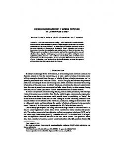
Figure 1: A TTA cluster with three fieldbusses A real-time computer system is always part of a larger system. This larger system is called a real-time system. A real-time system changes its state as a function of physical time, e.g., a chemical reaction continues to change its state even after its controlling computer system has stopped. It is reasonable to decompose a real-time system into a set of subsystems called clusters e.g., the controlled object (the controlled cluster), the real-time computer system (the computational cluster) and the human operator (the operator cluster). Figure 1 depicts the structure of a computational cluster, showing five nodes connected by a replicated TTP/C system bus (see [Kop97a]). Every node consists of three subsystems: at least one TTP/C controller, a host computer including the system and application software, and an interface to the environment via the TTP/A sensor bus, or a second TTP/C controller (in case of a gateway component). The relevant state variables of the real-time systems, e.g., those observed by the sensor devices (the small circles in Figure 1) in the controlled object, are called RT entities. The pictures of the RT entities in the computer system are called RT images. In any real-time computer system an applicationspecific temporal accuracy relationship between an RT entity and the associated RT image must always be maintained. For a more detailed explanation of this system model see [Kop97a]. The subsequent design principles guided the TTA and the design of the time-triggered sensor bus. (i) Global Time: In the TTA, it is assumed that all nodes have access to a global time of known precision in the microsecond range. This global time is based on the metric of the physical second. Since a failure of this global time base can have catastrophic consequences, the implementation of global time is fault tolerant. The global time is used to monitor the temporal accuracy of real-time data.
4
(ii) Temporal Firewalls: The real-time communication systems within the TTA are time-triggered. It is known a priori at design time when a particular message is transmitted on the communication system. The communication controllers hold their own local memory, containing the dispatching table (the message descriptor list MEDL) for the time-triggered communication system. The interface between a node and the communication system is a data-sharing interface which is free of control signals. Such a data-sharing interface is called a temporal firewall [Kop97b]. (iii) Unification of Interfaces: In the TTA, the temporal firewall is a fully specified (in the temporal and value domain) generic interface. It unifies the interface properties between host computer and the communication network, a host computer and the controlled object, a host computer and the man-machine interface, and a gateway interface between two clusters. This unification of the node interfaces simplifies the host software because the same mechanisms can be used to access the controlled object data and the network data. (iv) Two-Phase Design Methodology: The TTA supports a two-phase system design methodology: in the first phase the system architect specifies the functionality, the interaction patterns, and the interfaces to the subsystems. In the second phase the subsuppliers implement the functionality of the nodes. The interaction pattern design covers the specification of the MEDLs for each TTP controller and, thus, determines the properties of the temporal firewalls in each node. The MEDLs are loaded into the TTP controllers of each node and are inaccessible to the host computers of the nodes. The interaction patterns among the nodes cannot be influenced by the host software and can thus be validated independently of the host software. The composability of the TTA is based on this clear separation of concerns. An example for the contents of a temporal firewall specifications in an automotive control system is given in [Kop98]. In the second design phase, the host computer software is developed taking the fully specified temporal firewalls that have been fixed in the first design phase as a constraint. The host computer software can be tested in isolation with respect to these specified temporal firewalls, both in the value domain and in the time domain. Since the TTA architecture is composable, the properties validated for single nodes are maintained during system integration (composability). This two phase design methodology corresponds to the way large systems are built in many organizations. (v) Real-Time Database: Conceptually, the distributed real-time state-data in the temporal firewalls, formed by the temporally accurate images of all relevant RT entities, represent the real-time database. This real-time database is autonomously and periodically updated by the nodes of the cluster, which observe the environment and produce RT images. The
5
real-time database contains a temporally valid ”snapshot” of the current state of the cluster and the cluster environment. (vi) Scalability: Growth of a TTA is unconstrained because there is no central element in the architecture. Nodes can be expanded into gateway nodes by implementing a second CNI interface in the node. The CNI interface to the original cluster is not affected by this node-local change. Understanding a large TTA system can be decomposed into understanding the interaction patterns within each cluster, resulting in the temporal firewall specification and the functionality of each node of a cluster, taking the properties of the temporal firewalls as given. Every node views all other elements as its ”natural environment”, not being able to distinguish a controlled-object cluster from a computational cluster. This architectural characteristic is important during software development and testing, because a test simulator must have exactly the same interface, both in the value and time domain, as the controlled object. (vii) Generic Fault Tolerance: The TTA provides generic services for fault tolerance, such as a fault-tolerant clock synchronization, or a membership service at the hardware or system software level. The membership service informs a node about the activities of all other nodes in a cluster (see [Kop97a]). Ideally, the application software for fault-tolerant applications and non-fault-tolerant applications is the same.
3
The TTP/A Protocol
The TTP/A protocol [Kop95] is the low-cost multi-master sensor network for the TTA. In TTP/A, we distinguish between the active master that controls the operation of the protocol and the slaves that react to the activities of the master. TTP/A supports temporal predictability, but does not provide internal faulttolerance. The TTP/A protocol has been designed with the following objectives in mind: Small universal transducer interface: The interface of a transducer node must be understandable, data-efficient and predictable, similar to the proven 4-20 mA transducer-interface in the analog world. In TTP/A, the transducer data is represented in standardized byte-oriented state messages, which are transported across commonly available UART channels. From the point of view of a host application in a system node, the TTP/A data is presented in the established CNI-format of the time-triggered architecture, making no distinction between data collected locally via the TTP/A field bus and data collected remotely via the TTP/C system bus. Plug and play capability: Every TTP/A transducer node must support the basic TTP/A protocol for the exchange of data bytes. TTP/A provides an open-ended framework for the implementation of many different upwards compatible high-level protocols that provide plug and play capability. It is up to the transducer manufacturer to decide which ones of the higher-level 6
protocols will be supported in a particular implementation. Examples of high-level protocols are protocols for transducer identification, transducer documentation, calibration, built-in self test and diagnosis, state estimation, transducer agreement, and others. Sensor parameterization on power up: Every transducer node must contain a unique physical name. The customization of a transducer is performed in the power-up phase by the master node which holds the configuration information. It is thus possible to use transducers with the identical software in many different application domains. Multimaster protocol: In a TTP/A system there are two types of nodes: the powerful system nodes with a TTP/C and a TTP/A controller and the low-cost transducer nodes which support only the simple TTP/A protocol. A TTP/A bus can be connected to several system nodes, one acting as active master and the others as shadow masters. If the active master fails, a shadow master continues the operation. The decision to design TTP/A as a multi master and not as a distributed protocol (such as TTP/C) has been influenced by economic considerations – to make the transducer nodes as simple as possible. Flexible physical layers: The physical layer for the first version of the TTP/A protocol is based on the ISO 9141 standard for a single wire bus with a speed of 10 kbaud. In the future we envision the following further physical layers: single wire bus that includes the power supply, two-wire twisted pair for high-speed applications, and a fiber optic bus for applications that require physical isolation.
3.1
Hardware Requirements
As mentioned above, TTP/A distinguishes between two types of nodes: the simple transducer nodes and the more complex system nodes that act as fieldbus masters. Transducer Nodes Any properly programmed 8-bit or 16-bit microcontroller that supports external interrupt capability and a timer can be a transducer node in a TTP/A system. In the context of TTP/A, a transducer node is a slave that must execute the basic TTP/A slave protocol. The basic TTP/A slave protocol requires about 300 instructions of the controllers code space and 16 bytes of RAM including the code for a software UART. In a typical microcontroller, the execution of the protocol requires in the order of 40 instructions per byte received/sent. The software UART requires in the order of 200 instructions per transmission of a byte (20 instructions per bitcell).
7
Master Node A master node requires a dedicated protocol processor, e.g., a Motorola 68332 processor, timers, non-volatile memory for the storage of the protocol code and the application specific protocol data structures (the message descriptor list MEDL), a dual-ported memory for communication to the host processor, and a dedicated bi-directional UART channel for every supported TTP/A bus. The TTP/A CNI data structure that resides in the interface between the TTP/A controller and the host computer has the same syntactic and semantic appearance as the TTP/C CNI.
3.2
Principles of Operation
The basic TTP/A protocol is based on one-byte state messages. Most of these messages are data messages, while only one special message, the so called fireworks message, is a control message. Every protocol event either occurs at a predefined point of time (e.g., sending a message) or in a predefined time window (e.g., receipt of a message). Basic TTP/A Protocol In TTP/A, all communication activities are organized as rounds (Figure 2). A round consists of a sequence of slots where each node is assigned several slots for communication. This assignment is specified a priori in a round-descriptor list RODL. A slot is subdivided into the transmission phase (TP) and the inter frame gap (IFG). During the TP a data frame is transmitted, while during the IFG the protocol is executed. A slot is 16 bit cells long, where the TP occupies 11 bit cells (8 data bits, framing, and parity) and the IFG occupies 5 bit cells. A round starts with a special control message, the fireworks frame (FF), which is transmitted by the active master. The fireworks frame serves two purposes: • it is the global synchronization event for the start of a new round, and • it contains the name of the active RODL for this round. After the fireworks frame the active master transmits a second control frame, the parameter frame (PF). It contains the parameter byte which extends the information given in the fireworks byte. The parameter byte is followed by a sequence of data bytes from the individual nodes as specified in the active RODL. A round terminates when the end of the active RODL is reached. Each round is independent of previous rounds. To be able to differentiate between a fireworks byte and a data byte, the fireworks byte has characteristic features in the value domain and in the time domain: the fireworks byte has an even parity while all data bytes have odd parity; intermessage gap between the fireworks byte and the first data byte is significantly longer than the intermessage gap between the succeeding data bytes. These characteristic features make it possible for all nodes to recognize a new fireworks byte, even if some faults have disturbed the communication during the previous round. The characteristic features of 8
the fireworks byte simplify the reintegration of repaired nodes–a repaired node monitors the network until a correct fireworks byte is detected. Because each node is assigned its sending/receiving slots a priori by the definition of the RODL, it is not necessary to carry the identifier of a message as part of the message. All eight data bits of a message are true data bits. This improves the data efficiency of the protocol, particularly for the short one byte messages that are typical for field bus applications.
Figure 2: Structure of a TTP/A round
3.3
Views of a Sensor Node
In general, a sensor (or actuator) node must support the following two differing views: (i) Periodic real-time service view: This view sees a sensor as producing periodic observations of the RT entities in its environment. This is the view that supports the normal operation of the sensor. For example, a temperature sensor periodically sends the observed and locally preprocessed sensor value to the temporal firewall of the master. Since in TTP/A the time interval between sensing the environment and presenting the sensor value at the temporal firewall of the master is known a priori it is possible to perform a feed forward state estimation of the sensor value at the sensor node in such a way, that the delivered sensor value is a good estimate of the actual RT entity state at the point in time of delivery. (ii) The aperiodic diagnostic view: Most sensors need parameterization and calibration at startup and continuously collect diagnostic information to support the maintenance activities. For example a remote maintenance console can request diagnostic information from a certain sensor. For this purpose an aperiodic non-time-critical client-server connection to the sensor must be supported by a sensor protocol. TTP/A supports both views. From the point of view of a slave, both views have the same round structure, although different sensor RODLs are activated. It is the master that decides which one of these two views is activated in a particular round. In order to reduce the complexity of the software in the master, the handling of these two views inside the master is cleanly separated.
9
It is also possible to have two different masters that must coordinate their activities in the temporal domain for handling these two different views. A round that supports the periodic real-time service view is periodically activated by the master and the results of this round are presented in the temporal firewall of the master. For the normal use of a sensor, it is sufficient to understand this view of the sensor. Whenever a client-server request is initiated from a remote maintenance console (that may be connected over the INTERNET [Kuc98]), then a virtual circuit to the selected sensor node is established to support this type of communication. The TTP/A master activates a client-server round in such a way that the predictable operation of the periodic rounds is always maintained, i.e., the master activates the client-server round between periodic master rounds without affecting the temporal characteristics of the periodic real-time service view. Since the client-service requests are aperiodic and not time-critical, they can be delayed at the master until a time-window for their processing becomes available. The results produced by a sensor in response to the client-server request is transmitted to the requesting maintenance console via the dynamically established virtual circuit. Normally, the master does not interpret the contents of the request or the results of a client-server round, since in general it does not have access to a model of the internal sensor operation.
3.4
Physical Layers
Up to now, the TTP/A protocol has been implemented on the following physical layers: • single wire bus. This is the preferred implementation with a transmission speed of 10 kbauds as standardized in [ISO89]. • twisted pair. Applications requiring a shorter response time can use a twisted wire with CAN transceiver chips [ISO93]. • fiberoptics. TTP/A has also been implemented on a fiber optics bus [Pac95]. • further physical layers. A single wire that carries both power and signal against ground and wireless connections are still under consideration.
4
Time in TTP/A
It is a principle of the time-triggered architecture to provide a global notion of time to every node of the distributed real-time system. The different TTP nodes can have widely different hardware characteristics. The precision and the granularities of the time representations in the differing nodes vary in order to optimally match to the capabilities of the nodes. The TTP/A master, being a gateway between TTP/A and TTP/C, must be aware of the two distinct time representations in TTP/A and TTP/C and must transform these representations in a way that a designer working within one system is not aware of the differing time format in the other system. 10
4.1
Time Management
A slaves local time starts with each new round at the instant of receiving the parameter frame. Local time is valid for a duration of at most 124 slots. Before the end of this interval a new fireworks byte, which indicates the start of a new round, should be received. If none is received but the position of an event should be measured, the corresponding time value is filled with an in line error code indicating a timing error (bit value of the 4 bit error code is binary 0111). The time value of an event is coded in slot or bitcell granularity relative to the begin of the round (see section 5.3). To be able to distinguish between timevalues belonging to successive rounds, a time discrimination bit is transmitted by the master to the slaves in the fireworks byte and is altered between set and not-set between successive rounds (see section 5.3). An ongoing round can be resynchronized with the receive data interrupt (RDI) of every frame received from the master. For this purpose, the RODL entries of the slave node have a specific bit set aside to denote the corresponding frame orginates at the master (with its good clock). Every frame from the master can be used to resynchronize the state and the rate of the slave clocks.
4.2
Clock Synchronisation in TTP/A
A TTP/A cluster synchronizes the local clocks by means of a central master synchronisation. Thus it is assumed that the master node has a precise oscillator (maximum frequency deviation is less than 10−4 ss ) of the nominal frequency. The slave node can have an imprecise on-chip oscillator with a maximum frequency deviation within 50% of the nominal frequency and a drift rate of up to 10−1 ss . After start up the local knowledge of the slave nodes about the current frequency of its local on-chip oscillator is insufficient to support a simple serial UART communication. The slave node must therefore be synchronized from the master before a serial communication can take place. For this purpose, the TTP/A protocol provides a special synchronisation round for start up synchronisation see below). Later on in a round, during the transmission of the data frames, the slaves are periodically resynchronized by the master to improve the quality of the time base in the slaves. Startup Synchronisation A synchronisation round is periodically transmitted by the master. It consists of three consecutive slots which have even parity (like the fireworks frame). Figure 3 shows the synchronisation pattern on the communication channel. To generate this wave form, binary 01111110 is transmitted in these slots. After startup, a slave monitors the channel and waits until it can identify this wave form of the first two bytes on its digital input channel. The interval between two consecutive falling edges of the wave form corresponds to eight bit cells on the communication channel. Measuring this interval, the slave calculates the length of a bit cell and then sets the frequency of its UART, and
11
Figure 3: Wave form produced by two synchronization bytes reads the next byte with the UART. If this byte was read as binary 01111110 with even parity, the startup synchronization was successful. A synchronisation round can uniquely distincted from a communication round because there can never be two or more consecutive slots in a round with even parity, since all data bytes have odd parity. Continuous Clock Synchronisation During a standard round, the temporal distance between the start of a fireworks frame and the start of a parameter frame is precisely 4/3 of the slot duration between two data frames. This duration is called synchronisation interval see figure 2, section 3. The slaves measure this interval in order to recalculate their time base and to readjust their UARTs. The temporal duration between the start of the last frame of a round and the start of the fireworks frame of the next round must be longer than 5/3 of the slot duration.
5
Sensor and Actuator Data Types
To support interoperability, TTP/A supports several data encoding schemes. TTP/A distinguishes between three types of messages: restricted, unrestricted, and free messages. The restricted message reserves values between binary ’11110000’ and ’11111111’ of the first byte of the message for the transmission of error information. This implies that in a restricted message the first byte may not contain a data code value that is equal or larger than binary ’1111 0000’ because these codes are used for in-band error messages. An unrestricted message starts with a special first byte, which contains, the confidence code in the first half byte and the error code in the second half byte (see below). If an error code is set, the confidence marker in the first half byte must be ’1111’ (meaning no confidence). If the confidence marker equals any other value than ’1111’ the error code must be ’0000’ (meaning no error). All other bytes of an unrestricted message are application specific. There are no rules that restrict data coding of free messages. There is no error code in free messages. A TTP/A message can have between one and 62 bytes.
12
bit value 0000 0001 0010 0011 0100 0101 0110 0111 1000 1001 1010 1011 1100 1101 1110 1111
meaning of error half-byte No error occurred No message received Parity Error Code Space Error no sensor signal sensor signal erratic undefined sensor error time error measured value larger than specified range measured value smaller than specified range gradient of measured value larger than specified grandient of measured value smaller than specified Application specific error Application specific error Application specific error Application specific error Table 1: Error Codes
5.1
Error Codes and Confidence Markers
The TTP/A data encoding scheme provides the possibility to transmit error information and confidence information about a received data value. Both types of information are encoded in half-bytes. The error information replaces the data value and can be coded in-band. The confidence information is out-of-band and requires a special field in a message. Error Codes Error codes are used to inform the receiver that an error has occurred, either in the sensor or during the transmission, and that no valid data is available. The error codes described in Table 1 are provided in an half-byte error field. Some of the TTP/A data encodings support in-band error fields. The advantage of in-band error codes is, that data information or error information can be sent in the same byte and no additional byte for error messages is needed. Confidence Marker Confidence markers are introduced to give a smart sensor the capability to express its confidence [Par91, pp. 257-282] in an observed value. In a faulttolerant system where a number of sensor readings is available, the confidence markers can be used to select the sensor reading that has the highest plausibility or to manipulate the confidence marker. The confidence marker is a half byte that provides space for sixteen confidence classes (”0000” for highest confidence and ”1111” for ’no confidence’).
13
The confidence marker must to be transmitted out-of-band, since it is produced in addition (and not instead) of a data value. For example a TTP/A master controller receiving two measured values from two redundant sensors, both with a low confidence, can raise the confidence value, if the measured values are the same (see Table 2). Measured Value Confidence Value
Sensor 1 71 5
Sensor 2 71 6
Master 71 4
Table 2: Example for Evaluating Confidence Markers
5.2
Analog Data Types
Any kind of measured data that represents a value of an RT entity with a continuous range is called analog data. The data representation of analog values in TTP/A is modeled after the proven 4-20 mA sensor-interface of the analog instrumentation world. The unit of the representation is a defined fraction of the a priori known range of the sensor/actuator. Short Analog Data The short analog message is a restricted message that provides an eight-bit data field (a single byte) and represents an analog value between 0% and 100% of the a priori specified measurement range in steps of 0.5%, giving a total of 200 steps. If data bits 4 to 7 of a short analog message are all set, then the right half-byte of a short analog message must be interpreted as an error code. Since in a data message the bits 4 to 7 differ at least in one bit from binary ’1111’, this encoding scheme provides a hamming distance of at least two (including the parity bit) between valid error codes and valid data codes. Table 3 shows the encoding of a short analog message. Value [%] 0 . . 100 Error Codes
Value Encoding (binary) 0 . . 11000111 11110000 . 11111111
Value Encoding (decimal) 0 . . 199 240 . 255
Table 3: Short Analog Message Data Encoding
14
Standard Analog Message The standard analog message is a two-byte message introduced for values that require a higher resolution. The first byte of the standard analog message is identical to the short analog message and, thus, provides the capability to send in-line error codes. The second byte consists of two half bytes. The first half byte of the second byte extends the resolution of the first byte by four bits. The second half byte contains the confidence marker of the transmitted value. High Precision Analog Message The high-precision analog message is a two-byte message introduced for values that require a resolution of about 16 bits. The first byte of the high-precision analog message is identical to the short-analog message and thus provides the capability to send in-line error codes. The second byte extends the resolution of the first byte by 8 bits. A high-precision analog message does not have room for a confidence marker.
5.3
Time Formats
TTP/A distinguishes between two time formats, the short time format and the standard time format. Both time formats take the Receive Data Interrupt (RDI) of the parameter frame (PF) as their epoch and have a horizon of at most 120 slot durations. Short Time Format The short time format (1 Byte) expresses the time with a granularity of one slot duration. The first seven bits of the short time format identify a slot, since the epoch, i.e., the last RDI of the parameter frame. In order to maintain the in-line error coding capability, a time horizon of at most 120 slots after the epoch can be represented. The rightmost bit of the short time format is the round-discrimination bit. The round-discrimination bit is used to distinguish between consecutive rounds by alternating between set and not-set. The rounddiscrimination bit of the current round is transmitted by the master as the rightmost bit of the fireworks byte. Standard Time Format The long time format consists of two bytes. The first byte is the same as the short time format. The second byte has the same format as the second byte of the standard analog message. The first half byte of the second byte denotes in which one of the 16 partitions of the slot identified in the first byte an event has occurred. Since a slot has a duration of sixteen bit cells, the granularity of the standard time format corresponds exactly to the duration of a bit cell.
15
5.4
Digital Data
In the restricted format, up to 6 digital values can be encoded in the 6 righthand bits of a byte. The first two bits are not set if the byte contains a data value. All bits of the first half-byte must be set if the byte contains an error code in the second half-byte. A digital message can contain from one up to 62 bytes. Text The first character of a restricted text message must not be a special character from the ASCII alphabet to maintain the capability of encoding an error code in the first byte. If the first byte contains an error code, all bits of the first halfbyte must be set and the error code must be contained in the second half-byte of the first byte. Text can be transmitted non-real-time by adressing a certain node for text exchange by supplying its alias in the parameter byte or real-time by scheduling one slot per round for text transmission. In the real-time case, the message is transmitted as one character in each round in several consecutive rounds.
6
Fault-Tolerant Sensor Systems
There is a visible trend to high-dependability and fault-tolerant control system in the embedded system market for the following three reasons: (i) The successful use of high-dependability computer systems in critical applications, such as flight-control systems, has opened large new markets for embedded computer systems in application areas that up to now have relied on mechanical or hydraulic control systems. A good example for such a new high-dependability application is the emerging mass market of ”brake-by-wire” systems in the automotive industry. (ii) The production loss caused by a single failure of a control system in a highly automated production facility is often more significant than the cost of duplicating the control system hardware in order to provide a fault-tolerant control system that tolerates hardware failures. (iii) In a fault-tolerant system the expensive ”on-call” maintenance can be replaced by the less expensive regular preventive maintenance. The cost savings associated with such a change in the maintenance strategy can be larger than the additional cost for providing a fault-tolerant system.
6.1
Connection of a Single Sensor to a Replicated Bus
Connecting a single sensor to more than one bus system allows the system to tolerate faults of the communication media. Practically, a TTP/A sensor has two bus interfaces and thus can be connected to two different clusters (see figure 4).
16
Figure 4: Use of Replicated Busses in TTP/A Designing a node with double-bus interface it has to be considered that the node has to maintain independend protocol instances for each bus. An MCU which supports a timer unit with match capabilities and at least two external interrupts is sufficient to realize such a node with two bus interfaces.
6.2
Replicated Sensors
Using two replicated sensor per test point, each connected to either one or both of the replicated bus systems allows to tolerate faults of nodes (see figure 5).
Figure 5: Sensor Replication in TTP/A Figure 5 also shows how two master controllers can be connected to the replicated bus systems. Each master controls one cluster while listening on the other bus. If one of the master controllers fails, the other one takes control over the second bus.
6.3
Sensor Fusion in the Master
Another task of the master controller is the fusion of sensor values when there are replicated sensors in the system. In the CNI there are only agreed values of each test point visible. Also there can be a confidence marker supplied by the master for each test point. It is the result of the sensor agreement protocol executed in the master controller. (see section 5). The sensor agreement protocol takes sensor values and confidence markers supplied by the sensors as input and calculates an agreed value and confidence marker for several sensor readings of a test point.
17
7
Implementation Experience
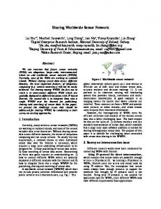
At the Institut f¨ ur Technische Informatik, the TTP/A master part as well as the TTP/A slave part of the protocol have been implemented for evaluation purposes. While the master protocol was implemented on the Motorola MC68376 using the powerful TPU onchip controller to realize the double bus interface, the slave protocol was implemented on an Atmel AVR8 MCU with a clock frequency of 1 MHz. The Tiny11, the cheapest model of the AVR8 series, was choosen. In huge quantities it costs only about 0.8 USD and, consequently, a node built up with this MCU costs about 2 USD including all components. Besides the MCU, a bus driver (MC33290 ISO K-line driver) and a voltage regulator is needed to built up a node.
Figure 6: TTP/A Slave Node Prototype
7.1
Hurdles on the Implementation
Different problems arised with the 8 bit architecture. • The 8 bit timer of the architecture cannot handle most of the desired timeouts because of its limited resolution. So, special timer routines had to be implemented. • The number of timeouts to be stored had to be minimized because the RAM was limited to 32 bytes. • The UART had to be implemented in software for two reasons:
18
Protocol Part
Frequency
UART send byte
at slots with a send activity for the node fireworks, parameter and each slot with a receive activity for the node for each slot of the round
UART receive byte
Protocol normal slot processing Protocol transmit data processing Fireworks and parameter frame processing
each slot with send or receive activity at beginning of round
Number of Instructions Executed 133
CPU Utilization
273
35 %
18
2%
27
20 %
67
21 %
20 %
Table 4: Instruction effort for different protocol activities – the recalibration of timeouts due to the inaccuracy and instability of the internal RC oscillator requires adjustable bit cell lengths in timer tick granularity. Most hardware UARTs do not support this function. – for economic reasons: The cheapest MCUs do not provide a hardware UART. For detailed information about the implementation of TTP/A on an 8 bit MCU see [Elm99].
7.2
Performance Evaluation
Table 4 lines up the number of assembler instructions needed for the different program activities. The CPU utilizition is given for a data transfer rate of 10 kBaud and execution times for a 1 MHz MCU. Increasing the Baud rate worsens the proportions. The maximum utilization is given during UART operations when receiving data. During all other protocol operations the workload is below the utilization of UART receive communications.
8
Conclusion
TTP/A, the low-cost member of TTP, is a multi-master sensor bus system. It meets the requirements of the TTA like provision of global time to the sensor nodes. To keep the complexity and thus cost of the smart-sensor nodes low, TTP/A is designed as master/slave protocol. The master, controlling the bus and maintaining data exchange with system networks or host computers, does the complex parts of the protocol. The sensor nodes execute the TTP/A slave protocol. 19
TTP/A supports multiple sensor views: an operational view, and a diagnostic view. Operational and maintainance activities are seperated to reduce system complexity. TTP/A provides data encoding rules, related to the well-known 4-20 mA standard, for sensor nodes including in-band error encoding and confidence markers. A fault tolerant sensor network can be built up with TTP/A by replicating the transmission media. Because all masters see the data of replicated busses, they can perform sensor agreement over multiple replicated sensors connected to different busses. The implementation of the slave TTP/A has shown, that low cost MCUs are sufficient to execute the slave part of the protocol and there is still enough CPU power left for application purposes.
20
References [Car98]
D Caro. What Does Real Time Mean Anyway. Instrument Society of America, page http://www.isa.org/journals/ic/octfloor/html, 1998.
[Dei98]
P. Deirauer and B. Woolever. Understanding Smart Devices. Industrial Computing, pages 47–50, 1998.
[Elm99]
W. Elmenreich and M. H. Holzmann. Implementation Details on the TTP/A Slave Protocol. Technical report, Institut f¨ ur Technische Informatik, Abteilung Echtzeitsysteme, Treitlstrasse 3, 182, April 1999.
[ISO89]
ISO. International Standard ISO 9141. International Organisation for Standardisation, Geneve, Switzerland, 1989.
[ISO93]
ISO. International Standard ISO 11898. International Organisation for Standardisation, CH-1211 Geneve 20, Switzerland, November 1993.
[Kop89]
H. Kopetz, A. Damm, Ch. Koza, M. Mulazzani, W. Schwabl, Ch. Senft, and R. Zainlinger. Distributed Fault-Tolerant Real-Time Systems: The MARS Approach. IEEE Micro, 9(1):25–40, Feb. 1989.
[Kop95]
H. Kopetz. TTP/A - A Time-Triggered Protocol for Body Electronics Using Standard UARTS. In International Congress and Exposition Detroit, Michigan, Commonwealth Drive, Warrendale, Febr.-March 1995. The Engineering Society For Advancing Mobility Land Sea Air and Space, SAE International.
[Kop97a] H. Kopetz. Real-Time Systems, Design Principles for Distributed Embedded Applications. Kluwer Academic Publishers, Massachusetts, 1997. [Kop97b] H. Kopetz and R. Nossal. Temporal Firewalls in Large Distributed Real-Time Systems. In Proceedings of IEEE Workshop on Future Trends in Distributed Computing, pages 310–315, Tunis, Tunesia, 1997. IEEE Press. [Kop98]
H. Kopetz and T. Thurner. TTP – A New Approach to Solving the Interoperability Problem of Independently Developed ECUs. Technical report, SAE, Detroit, Michigan, February 1998.
[Kuc98]
M. Kucera, H. Kopetz, D. Millinger, C. Ebner, and I. Smaili. Interfacing Time-Triggered Embedded Systems to the INTERNET. In Proceedings of the 1st International Symposium on Internet Technology, pages 180 – 186, Taipei, Taiwan, April 29 - May 1 1998.
[Pac95]
Hewlett Packard. DC to 10 MBd Versatile Link with Plastic Optical Fiber or Hard Clad Silica Fiber (HCS) for Factory Automation and Industrial Applications. Hewlett Packard Co., 1995. Application Note 1080. 21
[Par91]
B. Parhami. A Data-Driven Dependability Assurance Scheme with Applications to Data and Design Diversity. Springer Verlag, Vienna, 1991.
[Ran95]
B. Randell and et al. J. C. Laprie. Predictably Dependable Computing Systems. Springer Verlag, Heidelberg, 1995.
22