Equation (21) can be calculated resolving numerically. â. âp Ssat = 0. It has at least one solution in [0, 1], since Ssat is zero if J>Qmax, p = 0 and p = 1, and it is ...
A MAC Protocol for Half-Duplex Multi-Packet Detection in SC-FDE Systems M. Pereira(1)(2)(3) , L. Bernardo(1)(3) , R. Dinis(1)(2) , R. Oliveira(1)(3) , P. Carvalho(1)(3) and P. Pinto(1)(3) (1) FCT-UNL, New Univ. of Lisbon, Portugal (2) ISR-IST, Tech. Univ. of Lisbon, Portugal (3) UNINOVA, Monte da Caparica, Portugal Abstract - This paper deals with multi-packet detection for SC modulations (Single-Carrier) with FDE (FrequencyDomain Equalization). We consider iterative frequencydomain receivers that jointly perform the equalization, multi-packet separation and channel decoding operations. Our receivers allow a high throughput provided that the number of mobile terminals that is trying to access a given slot is equal to or below the multi-packet detection capacity Qmax . We propose a new MAC protocol that allows a total number of mobile terminals J above Qmax by controlling the number of mobile terminals contending to transmit. The paper evaluates the uplink saturated system throughput and proposes an optimal configuration for the packet transmission probability associated to each mobile terminal. Our analytical results are validated using physical and MAC layer simulations.1 I. I NTRODUCTION In wireless systems multiple users might try to access a given channel and the objective of MAC protocols (Medium Access Control) is to allow this in an efficient way. When different users are simultaneously accessing a given channel a collision occurs. The conventional approach to cope with collisions is to discard all blocks involved in the collision and to retransmit them. Multi-packet detection mechanisms use the signals associated to multiple collisions to separate the packets involved. It can be shown that solving collisions can be regarded as a multiuser detection problem [1]. In [2] a multi-packet detection technique was proposed where all users involved in a collision of Q packets retransmit their packets Q−1 times. To allow packet separation different phase rotations are employed for different packet retransmission. An important drawback of the technique of [2] is that it is only suitable for flat-fading channels. For this reason, it was extended to multi-path time-dispersive channels [3]. Since [3] considers a time-domain receiver implementation, its complexity can be very high for severely time-dispersive channels. Moreover, due to the linear nature of the receivers described in [2] and [3] the residual interference levels can be high and/or can have significant noise enhancement. There are also phase rotations that might lead to an ill-conditioned packet separation 1 This work was partially supported by the FCT (Fundac ¸ a˜ o para a Ciˆencia e Tecnologia) under the pluriannual funding, the project U-BOAT, and grant SFRH/BD/41515/2007.
(e.g., if we have two users with similar phase rotations in flat fading channels). In [4] we proposed a frequency-domain multi-packet receiver that allows an efficient packet separation in the presence of successive collisions. This receiver is suitable to severely time dispersive channels and does not require uncorrelated channels for different retransmissions. However, the MAC protocol proposed on these two systems assume that the receiver is always able to separate all receiving packets regardless of the number of mobile terminals (MTs) in the system, which may be too complex for base stations (BS) supporting a large number of MTs. In a practical implementation the multi-packet receiver is able to handle a limited maximum number of packets (Qmax ), which is much lower than the number of active MTs. Therefore, the MAC protocol must be designed to avoid having more than Qmax MTs transmitting a packet simultaneously. A static channel slot assignment can be used to get the optimal throughput for saturated load [5]. For variable load, collision avoidance can be achieved by applying a channel slot reservation mechanism controlled by the senders [6] or by the receivers [7]. [6] assigns a pair of RTS (Request To Send) / CTS (Clear To Send) bits to each MT, and the BS controls who transmits in the next data slot, producing a significant overhead for a large number of MTs. In [7] the BS selects the set of transmitters for each slot, based on the information about previous slot usage. Another alternative is to let collisions happen, and to resolve them. Slotted Aloha algorithm [8] retransmits failed packets with a probability p. On TA (Tree Algorithm) approaches the contending MT set is reduced by half after a collision. [9] proposes SICTA which combines a TA with a SIC scheme (Successive Interference Cancelation). In SICTA the collided packet signals are used to extract the individual packets, assuming a flat-fading channel. It achieves a maximum stable throughput of 0.693. This paper extends the MAC protocol proposed in [2], [4] to cope with a limited Qmax lower than the number of MTs (J), and with half-duplex radios. When Q ≤ Qmax packets are transmitted in one slot, the sending MTs capture the channel for Q data slots, allowing the reception of all packets at the BS (base station). If Q > Qmax packets are transmitted the detection fails, and the duration of the channel capture will depend on the number of packet retransmissions required to reduce Q to a value equal to or below Qmax . After each detection failure, MTs continue contending with a
978-1-4244-2517-4/09/$20.00 ©2009 IEEE
probability p, up to maxc times. If the limit is reached all packets are dropped. Therefore, a p-persistent Slotted Aloha algorithm is used to control the number of MTs contending for the channel, where the BS defines the MTs probability of sending a packet in the next data slot. This paper extends the frequency-domain multi-packet detection scheme proposed in [4] so as to allow joint equalization, multi-packet separation and channel decoding. In fact, our receiver can be regarded as a frequency-domain turbo multi-packet receiver since. This paper is organized as follows: the system characterization is made in sec. II and our multi-packet detection technique is described in sec. III. The MAC performance and the optimal configuration for saturated networks is analyzed in sec. IV. A set of performance results is presented in sec. V. Sec. VI is concerned with the conclusions of this paper. II. S YSTEM C HARACTERIZATION In this paper we consider the transmission in structured wireless systems employing SC-FDE schemes, where a set of J MTs send data to a BS (Base Station)2 . MTs are low resource battery operated devices whereas the BS is a high resource device, which runs the multi-packet detection algorithm in real-time. MTs have a half-duplex radio that may not support multi-packet detection to reduce its complexity. The MTs run a p-persistent Slotted Aloha algorithm to send data frames using the time slots defined by the BS (for the sake of simplicity, it is assumed that the packets associated with each user have the same duration, ldata ). It is assumed that different data frames arrive simultaneously and that perfect power control exists, able to compensate the different propagation times and attenuation. We also assume a perfect synchronization between local oscillators. Packets are transmitted as a sequence of FFT time-domain blocks, preceded by a physical preamble. The physical preamble is used to estimate the channel, synchronize the reception and detect the users involved in a possible collision. A. MAC protocol The BS broadcasts SYNC (Synchronization) control frames marking the beginning of an epoch, and defining p, the MT probability of transmitting a data frame. Using p the BS controls the number of MTs contending for the channel, without directly controlling who may transmit in the next slot. Each epoch is composed by one or more slots, associated to one or more reception phases. When the number of MTs transmitting a packet during a reception phase (Q) is equal to or below Qmax the BS broadcasts an ACK (Acknowledgement) control frame at the end of the first slot forcing the MTs to retransmit the data frames Q − 1 times. The epoch ends at the end of the detection phase and the Q packets may be received, depending on the reception error probability. A reception phase has only one slot if more than Qmax MTs transmit. On this case the BS broadcasts an ACK frame, defining the retransmission probability for the next slot p, thus reducing the number of 2 the system design also allows the definition of an ad hoc operation mode, with MT to MT communication.
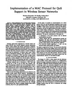
Fig. 1.
MAC protocol example.
MTs contending if p < 1. A MT may transmit in the next reception phase only if it transmitted in the previous reception phases of the epoch. The BS may send up to maxc ACK frames due to overpopulated reception phases, before finishing the epoch with a SYNC frame. The ACK and the SYNC frames include a list of detected senders, and a bit mask acknowledging the reception of data frames on the previous slot. Therefore, when the SYNC frame is received a MT knows if its data frame was correctly received by the BS. We assume that frames not received in an epoch are successively retransmitted in the next epochs, until they are received by the BS. Fig. 1 illustrates four possible situations that may occur during the MAC operation, with 3 MTs and Qmax equal to 2. An initial successful epoch with 2 active senders, is followed by an empty epoch, both with a single reception phase. The third epoch is composed by two reception phases: it starts with an initial overpopulated reception phase followed by a successful one with two slots, triggered by an ACK frame that leads to the exclusion of MT 2 from the senders group. and a last successful epoch with a single slot and a single sender. Data packets and the SYNC and ACK packets from different senders are spaced by a SIFS (Short Inter-Frame Space) time, to support the commutation between sending and receiving mode. No spacing is used between retransmitted packets during the multi-packet detection phase. Due to the half-duplex approach and to the physical and MAC header length, it is not possible to achieve a full channel throughput utilization. The best possible throughput for scheduled traffic is achieved when Qmax MTs transmit on all slots. This minimizes the PER (Packet Error Ratio) and the number of SIFS times wasted per packet received. The throughput bound is given by
S≤
Qmax ldata lsync +lack +2hphy +Qmax (hmac +ldata )+4lsif s
,
(1)
where, lsif s represent the number of bytes equivalent to the SIFS duration, hphy and hmax represent the length of the physical and MAC headers, and lsync , lack and ldata respectively the SYNC, ACK and DATA frames length.
(r,i) and F˘k,q obtained from the set of Q equations:
III. R ECEIVING M ULTIPLE PACKETS A. Receiver Structure When Q < Qmax data frames are involved in a collision during a receiving phase, each user retransmits its packet Q−1 times. Therefore, the receiver has Q versions of the signals associated to the Q packets and jointly detects all packets involved. We consider an iterative joint equalizer and multipacket receiver where each iteration consists of Q detection stages, one for each packet. When detecting a given packet we remove the residual interference from the other packets. The receiver structure for the detection of the qth packet and the ith iteration uses Q frequency-domain feed-forward filters, each one associated to the signal of a given collision (i.e., one retransmission), and Q frequency-domain feedback filters, each one using the average value of the data signal associated to each packet. The kth frequency-domain sample associated to the qth packet is (i) A˜k,q =
Q �
(r,i)
(r)
Fk,q Yk
−
Q � q � =1
r=1
(q � ,i)
(i−u(q � −q))
Bk,q Ak,q�
.
(2)
(r)
{Yk ; k = 0, 1, . . . , N − 1} is the received frequency-domain block, and u(x) is the unitary step function, i.e., u(x) = 0 for (i) x < 0 and 1 for x ≥ 0. The average values Ak,q� are obtained (i)
as follows. The block {Ak,q� ; k = 0, 1, . . . , N − 1} is the DFT (i) (i) of the block {an,q ; n = 0, 1, . . . , N − 1}, where an,q denotes the average symbol values conditioned to the FDE output that can be computed as described in [4]. The feedforward and feedback coefficients are selected to minimize the ”signal-to-noise plus interference ratio”, for a given packet and a given iteration. This optimization problem can be written as the minimization of E[|A˜k,q − Ak,q |2 ], k = 0, 1, . . . , N − 1 (i)
(3)
conditioned to N −1 nQ 1 � � (r,i) (r) Fk,q Hk,q = 1. N r=1
(4)
k=0
is the overall channel frequency response for the pth user and the rth transmission attempt. This optimization can be performed using the Lagrange’s multipliers method. After some straightforward but lengthy manipulations we get the optimum feedforward coefficients (r,i)
(r,i) F˘k,q (i)
γq
,
(5)
with γq(i) =
N −1 Q 1 � � ˘ (r,i) (r) Fk,q Hk,q , N r=1 k=0
+
� q � �=q
(i)
Q �
(r)∗
(1 − |ρq� |2 )Hk,q�
r � =1
�
Q � r � =1
�
�
(r ,i) (r ,i) F˘k,q F˘k,q
�
(r ,i) (r ) (r,i) F˘k,q Hk,q� + αF˘k,q = (r)∗
= Hk,q , r = 1, 2, . . . , Q,
(7)
The feedback coefficients are then given by (q � ,i)
Bk,q
=
Q �
(r)
(r,i)
Fk,q Hk,q� − δq,q�
(8)
r=1
(δq,q� = 1 if q = q � and 0 otherwise). Equations (7) might not have a solution or it can be ill conditioned if the correlation between channels associated to different retransmissions is high. For systems where this is not practical, we assume that the frequency domain block associated to the rth retransmission of the qth packet, (r) {Ak,q ; k = 0, 1, . . . , N − 1}, is a cyclic-shifted version of {Ak,q ; k = 0, 1, . . . , N − 1}, with shift ζr . In this paper we assume that the different ζr are the odd multiples of N/2, N/4, N/8, . . . (see [4]). This allows small correlation (r) between different Hk,q , for each frequency (naturally, as we increase r we increase the correlations). Moreover, envelope (r) fluctuations on the time-domain signal associated to {an,q ; n = 0, 1, . . . , N − 1} are not too different from the ones associated to {an,q ; n = 0, 1, . . . , N − 1}. B. Use of Channel Decoder Outputs in the Feedback Loop As with other turbo equalizers, we can also define a multipacket detector that employs channel decoder outputs instead of the uncoded ”soft decisions” in the feedback loop. The receiver structure is similar, but with a SISO channel decoder (Soft-In, Soft-Out) employed in the feedback loop. The SISO block, that can be implemented as defined in [10], provides the LLRs of both the ”information bits” and the ”coded bits”. The input of the SISO block are LLRs of the ”coded bits” at the multi-packet receiver, and the feed-forward coefficients are obtained from (5)-(7). IV. P ERFORMANCE A NALYSIS AND O PTIMIZATION
(r) Hk,p
Fk,q =
(1 −
(r)∗ 2 |ρ(i) q | )Hk,q
(6)
This section evaluates the system throughput and proposes an optimization for the p parameter for saturated scenarios. We define bi(n, k, p) as the binomial distribution probability mass function � � n (n−k) . (9) bi(n, k, p) � pk (1 − p) k Due to the serial structure of the packet detector, the PER (Packet Error Rate) is influenced by the number of sending MTs (Q) and by the order of the user detection. In this model we consider only the average PER amongst MTs, defined as �Q = P ERQ . We also assume that no errors occur in the downlink broadcast transmissions, from the BS to the MTs.
The probability of the BS correctly receiving k packets when Q are transmitted is [C]Q,k = P {k packets received | Q are transmitted} � bi (Q, k, 1 − �Q ) 0 ≤ k ≤ Q , 1 ≤ Q ≤ Qmax . (10) = 0 k > Q , Q > Qmax
because the overpopulated cases will be handled on a future reception phase. c = maxc represents the last retransmission on an epoch, and Limit (maxc ) is equal to J. Similarly, the expected number of bytes received in the cth reception phase of an epoch is
When Q packets are transmitted on a reception phase the expected number of packets jointly detected is θQ =
Q �
k [C]Q,k ,
(11)
where tphy is the duration of the physical header, tsif s is the SIFS duration, and tdata is the data frame duration assumed constant. tsync is the SYNC frame duration, which is equal to the ACK frame duration. Empty or overpopulated reception phases last a single slot, and include the data transmission time (tdata ), an ACK time (tsync ) and the related headers (tphy ) and SIFS, as represented in Fig. 1. Otherwise, the reception phase lasts Q slots, including one ACK and one SYNC frame (2tsync ). A network is saturated when a MT has always a new frame to transmit. For a saturated network MTs transmit with probability p. A reception phase fails due to overpopulation when the number of MTs (J) is above Qmax . Up to maxc + 1 reception phases may exist in an epoch due to successive overpopulated reception phases. After reception phase c, the remaining MTs transmit with probability p, generating a distribution mass function for the number of transmitting MTs defined by ⎧ c=0 ⎪ ⎨bi(J, n, p) J � (13) η c (n) = ηc−1 (i) ⎪ bi(i, n, p) c > 0 ⎩ p col c−1 i=Qmax +1 where pcolc is the probability of having a new overpopulated reception phase after c consecutive overpopulated reception phases: �
J n=Qmax +1 ηc (n) J > Qmax pcolc = . (14) 0 J ≤ Qmax From (13) we get the expected duration of the cth reception phase of an epoch: �
Limit(c)
durc =
(cδsat + δQ ) ηc (Q) ,
(15)
Q=0
being δsat = δQmax +1 the duration of a overpopulated reception phase. Limit(c) is equal to Qmax if c < maxc
(ldata × θQ ) ηc (Q) .
(16)
Q=0
From (15) and (16) we get the epoch expected duration, given by
k=1
and the expected duration of the reception phase is ⎧ Q ≤ 1, ⎪ 2tphy +tdata +2tsif s +tsync ⎪ ⎪ ⎨ Q > Qmax δQ = , (12) ⎪ 1 Qmax , p = 0 and p = 1, and it is positive for p ∈]0, 1[. p∗sat is the optimal value for p for saturated conditions, and depends only on J, Qmax and on the P ER values. Ssat (p∗sat ) defines the maximum network throughput. ∂ ∂p Ssat
V. S IMULATIONS In this section, we present a set of performance results concerning the proposed detection techniques in the presence of multiple collisions. Each FFT blocks has N = 128 bits (256 data symbols with rate 1/2), with length 4μs, and each data packet has 64 FFT blocks. The data symbols are selected from a QPSK constellation under a Gray mapping rule. The channel encoder is the well-known rate-1/2 64-state convolutional code with generators 1+D2 +D3 +D5 +D6 and 1+D+D2 +D3 +D6 . We used the channel decoder outputs in the feedback loop, as in conventional turbo detection schemes. The radio channel associated to each packet is characterized
0
10
1
(o): Q=1 (*): Q=2 (+): Q=3 (Δ): Q=4
0.9 0.8
Throughput
BLER
0.7
____
−1
: UC − − − : SP
10
0.6 0.5 0.4
: Eb/No = +1dB : Eb/No = +3dB : Eb/No = +5dB : Eb/No = +11dB : Sim − Eb/No < +11dB : Sim − Eb/No = +11dB
0.3 0.2 0.1 −2
10
Fig. 2.
−6
−4
−2
0 Eb/N0(dB)
2
4
0
6
0.2
0.4
0.6
0.8
1
p
BLER after 4 iterations, for Q = 1 (without collision), 2, 3 and 4.
by the power delay profile type C for HIPERLAN/2 (HIgh PERformance Local Area Network) [11], with uncorrelated Rayleigh fading on the different paths and the signals associated to all users have the same average power at the receiver (i.e., the base station), which corresponds to a scenario where an ”ideal average power control” is implemented. We consider perfect synchronization and channel estimation conditions. The channel for each packet retransmission was a shifted version of the channel in the first attempt, as described in sec. III. We consider Poisson sources and we assume that the BS knows how many packets are involved in the collision, as well as the MT that transmitted each packet, when Q ≤ Qmax . Fig. 2 show the average BLER (Block Error Rate), averaged over all users, after four iterations, when Q= {1, 2, 3, 4}, for UC (Uncorrelated Channel) and applying SP (Shifted Packets technique). The results are expressed as function of Eb /N0 , where N0 is the one-sided power spectral density of the noise and Eb is the energy of the transmitted bits associated to a given block transmission. PER can be obtained from BLER using equation (22). Clearly our technique is able to cope with a large number of collisions, with improved performances as we increase the number of packets involved in the collisions (and, consequently, the number of retransmissions), even with the SP technique (with the same channel for each retransmission). P ER = 1 − (1 − BLER)
0
hmac +ldata 16
.
(22)
For evaluating the MAC performance we add the assumption that BLERQ for data packets is a mean-ergodic process. Thus the Eb /N0 effects can be modeled on a discrete event simulator by a matrix with the average P ERQ,q values for Q jointly decoded packets, and for the qth packet in the decoding chain. We implemented the multi-packet detection physical layer and the MAC protocol in the ns-2 simulator [12]. The following simulation parameters were used below : ldata = 990 Bytes; lack = lsync = 64Bytes; hmac = 34Bytes; hphy = 24Bytes; Data Rate = 1Mbps; and tsif s = 10μs. BLERQ,q values were taken from the same set of physical layer simulations as the subset presented in Fig. 2, for the
Fig. 3.
Throughput with p for Eb /N0 = {1, 3, 5, 11}dB.
Shifted Packet technique. The simulation scenario placed the J MTs on a circle centered in the BS with radius 10m, within the perfect power control range. In order to reach saturation, each MT runs a Poisson packet generator with a average rate of λ = 200 packets/sec and it has a MAC queue with a capacity for 50 packets. The maximum local MT throughput, defined by Ssat (p∗sat | J), is reached for J = 1 with a capacity of 99.8 packets/sec. MTs generate traffic on the simulation interval [9, 900] but throughput is measured in the interval [10, 900], to guarantee that all queues are full. The results shown below are the averages of five independent simulations, with different random seeds. Fig. 3 depicts the simulation and the model (20) saturation throughput with p, for Eb /N0 ranging from 1dB (heavy packet losses for Q = 1) to 11dB (no losses), and for J = 8 and Qmax = 4. Throughput values are relative to Ssat the data rate, and are calculated as Data Rate . The Figure shows that the measured throughput follows the model values, thus validating the model. The half-duplex approach and the headers overhead bound the throughput (1) to a value ranging from 0.916 for Eb /N0 = 11dB to 0.915 for Eb /N0 = 1dB, on a perfect scheduled system [5]. Fig. 3 shows that the proposed system has a maximum stable throughput value of 0.835 for Eb /N0 = 11dB and 0.742 for Eb /N0 = 1dB, with p∗sat values respectively of 0.327 and 0.408. Therefore, the MAC protocol throughput degradation (in relation to the maximum bound) increases for lower Eb /N0 . However, even for Eb /N0 = 1dB the proposed system outperforms the maximum stable throughput of SICTA (0.693). Fig. 4 and Fig. 5 show the maximum saturation throughput in function of Qmax and J for Eb /N0 = 11dB and Eb /N0 = 1dB respectively. They clearly show the throughput gains that can be achieved by using multi-packet detection, specially for low Eb /N0 values. The throughput increment decreases with the Qmax value, showing that there is a tradeoff between the multi-packet detection complexity and the additional throughput gains when Qmax is increased.
Future work includes the development of improved block level error recovery mechanisms and the evaluation of the system performance with unsaturated networks and heterogeneous loads.
1 0.9 0.8
Throughput
0.7
R EFERENCES
0.6 0.5 0.4 0.3
: Qmax = 1 : Qmax = 2 : Qmax = 4 : Qmax = 10 : Simulation
0.2 0.1 0
1
2
3
4
5 6 7 Number of MTs (J)
8
9
10
Throughput with J and Qmax , for Eb /N0 = 11dB and p = p∗sat .
Fig. 4.
1 0.9 0.8
Throughput
0.7 : Qmax = 1 : Qmax = 2 : Qmax = 4 : Qmax = 10 : Simulation
0.6 0.5 0.4 0.3 0.2 0.1 0
Fig. 5.
1
2
3
4
5 6 7 Number of MTs (J)
8
9
10
Throughput with J and Qmax , for Eb /N0 = 1dB and p = p∗sat .
VI. C ONCLUSIONS In this paper we proposed a MAC protocol for a frequencydomain multi-packet receiver for the uplink of broadband wireless systems employing SC-FDE schemes. Our detection technique allows efficient packet separation, even when the channel remains fixed for different transmissions. Our MAC protocols allows J MTs (above the multi-packet detection capability) to efficiently use such mechanism as long has the BS defines p = p∗sat , using only local information (J, Qmax , and the measured MT P ER values). Therefore, it can be used in practical deployments.
[1] S. Verdu, Multiuser Detection, Cambridge, UK, 2003. [2] M. Tsatsanis, R. Zhang and S. Banerjee, “Network Assisted Diversity for Random Access Wireless Systems”, IEEE Trans. on Signal Processing, Vol. 48, pp. 702–711, Mar. 2000. [3] R. Zhang and M. Tsatsanis, “Network-Assisted Diversity Multiple Access in Dispersive Channels”, IEEE Trans. on Communications, Vol. 50, No. 4, pp. 623–632, April 2002. [4] R. Dinis, P. Carvalho, L. Bernardo, R. Oliveira, M. Serrazina, and P. Pinto, “Frequency-Domain Multipacket Detection: A High Throughput Technique for SC-FDE Systems”, IEEE Globecom’07, Washington, USA, Nov. 2007. [5] I. Chlamtac, and A. Farag, “An Optimal Channel Access Protocol with Multiple Reception Capability”, IEEE Trans. on Computers, Vol.43, pp.480–484, Apr. 1994. [6] Y. Eisenberg, K. Conner, M. Sherman and J. Niedziecki, “MUD Enabled Media Access Control for High Capacity, Low-Latency Spread Spectrum Communications”, IEEE MILCOM’07, Orlando, USA, Oct. 2007. [7] Q. Zhao, and L. Tong, “A Multiqueue Service Room MAC Protocol for Wireless Networks With Multipacket Reception”, IEEE/ACM Trans. on Networking, Vol.11, pp.125–137, Feb. 2003. [8] R.-H. Gau, “Performance Analysis of Finite-User Slotted Aloha in Wireless Networks with Multiple Packet Reception and Random Traffic”, IEEE Comm. Letters, Vol.12 pp.140–142, Feb. 2008. [9] Y. Yu and G. Giannakis, “SICTA: A 0.693 Contention Tree Algorithm Using Successive Interference Cancellation”, IEEE INFOCOM’05, Miami, USA, Mar. 2005. [10] B.Vucetic and J.Yuan, Turbo Codes: Principles and Applications, Kluwer Academic Publ., 2002. [11] ETSI, “Channel models for HIPERLAN/2 in Different Indoor Scenarios”, ETSI EP BRAN 3ERI085B, pp. 1–8, March 1998. [12] The Network Simulator ns-2 (2.33). Retrieved from http://www.isi.edu/nsnam/ns/.