Earthing and instrumentation not shown. energizing the experiment. The resistor Rd provides contin- uous conduction through the spark gaps to ensure that they.
A Marx Generator for Exploding Wire Experiments Rowan Sinton, Ryan van Herel, Wade Enright, and Pat Bodger Electrical and Computer Engineering Department University of Canterbury New Zealand.
Abstract—A two-stage Marx generator was designed, constructed and tested for the purpose of investigating long distance exploding wire experiments. The voltage and energy requirements for the experiments are unique; up to 180 kV and 40 kJ is required. Capacitor banks, earthing switches, spark gaps and resistors were purpose-built. Using the completed setup, conductive plasma paths up to 36 m long have been investigated.
I. I NTRODUCTION Research into the exploding wire (EW) phenomenon has been active for over half a century [1]. Researchers have focused on a wide range of aspects of EW; from determining the characteristics of its many physical mechanisms [2], [3] to applying it to specific applications [4]. Researchers at the University of Canterbury are using EW to create long distance conductive plasma paths [5], which have been used to wind novel electrical machines [6]. The plasma paths are also being used to investigate interactions with atmospheric electricity (fig. 1). In this research, EW is formed by applying a large electrical impulse from a capacitor bank to a thin enameled copper wire. The wire then undergoes rapid Ohmic heating and melting. If favorable conditions exist, ‘beads’ of plasma appear at discrete locations along the wire’s length [7]. These plasma beads may then grow and form a continuous plasma path. The remaining capacitor energy then discharges through the plasma, which is called ‘restrike’. It has been determined that a supply voltage of between 5 and 10 kV per meter of wire is necessary for reliable restrike. The supply must also have enough capacitance to maintain sufficient voltage through the melting and plasma bead formation stages, or the process of EW will stall prematurely. The energy supply for exploding wire experiments at the University of Canterbury has previously consisted of a single bank of capacitors rated to 60 kV, 21.4 µF [8]. This allows creation of a plasma path up to 12 m long. Researchers wishing to achieve longer plasma paths need a proportionally higher voltage output from the energy supply. A Marx generator (multistage impulse generator) configuration was chosen to achieve this. This design charges multiple capacitor stages in parallel (requiring a relatively small step-up transformer and rectifier) and discharges them in series. This paper details the design, construction and safe operation of such an energy supply, and provides preliminary results obtained using the supply.
Fig. 1: A 10 m plasma path, created vertically to a weather balloon, used for outdoor atmospheric studies.
II. D ESIGN A Marx generator is conventionally a tower of capacitors and insulators, often consisting of 10 or more stages. The output voltages are high – typically 1 to 3 MV, but the capacitances are low – typically tens of nanofarads. The energy supply for long distance EW experiments requires relatively low voltages but high capacitance, i.e. fewer stages are needed, but each stage is physically much larger and heavier. Therefore, rather than stacking stages into a tower configuration, they were kept separate and placed on individual insulators. The design presented in this paper consists of just two stages, but is upgradeable to three. Figure 2 shows a circuit diagram of the two-stage Marx generator. The two capacitor stages, S1 and S2 charge in parallel through resistors Rc . When they have been charged to the required voltage, the supply is isolated on the l.v. side of the transformer and spark gap S1 is triggered. Spark gap S2 then experiences an overvoltage of approximately twice the charging voltage, causing it to breakdown and subsequently
0 -230 V
Rl
Rc C1
S1
S2 C2
EW Rd
Rc Fig. 2: A circuit diagram of the two-stage Marx generator. Earthing and instrumentation not shown. energizing the experiment. The resistor Rd provides continuous conduction through the spark gaps to ensure that they remain ionzied for the full duration of the experiment, and also dissipates remaining energy after the experiment. A. Capacitor Stages The available capacitors are oil-filled, 17.1 µF, 15 kV d.c. capacitors. Each weighs approximately 60 kg. The existing charging circuit has an output of 90 kV d.c., so this was chosen as the maximum stage charging voltage. Each stage therefore consists of 6 capacitors in series, and two in parallel to achieve sufficient capacitance for sucessful EW experiments. Each stage of 12 capacitors has an overall capacitance of 5.7 µF and weighs approximately 720 kg. There are many different possible physical layouts for the capacitors, each with its own merits. One must consider structural integrity, electrical insulation, ease of connection to the circuit, cost of materials, and impact of capacitor failure. The final design consisted of stacks of three pairs of capacitors bolted together. The pairs were laid flat for maximum stability. However, the designed failure mode of the capacitors is to expand via relief ribbing in the sides of the cases, so structural supports were to be exterior to allow for expansion in the unlikely event of a capacitor failure. The supports also needed to be a very good electrical insulator, as there would be up to 30 kV d.c. between the pairs and 15 kV d.c. from the bottom pair to ground. Four lengths of channel-section pulltruded fiberglass were used as a frame for each stack of 6 capacitors. Two of these 6-capacitor stacks were connected in parallel to complete each stage (fig. 3). The two-stage Marx generator, when triggered, has an effective rating of 180 kV d.c., 2.85 µF, giving a total energy of 46.17 kJ. B. Protective Earthing There are 6 capacitors in each stage that need to be individually earthed after each experiment. It is not enough to earth each stage as a whole; due to uneven leakage currents in the capacitors, lethal voltages often remain within the stage after an experiment. The earthing system needs to be fast and simple to apply, to minimize experiment turn-around time and reduce the chance of an operator error. Earthing ‘levers’ were built, which rotate from a horizontal (disconnected) position to a vertical (connected) position. Each lever has spring-loaded piston contactors which press against
Fig. 3: One capacitor stage (with earthing lever applied). contact points on the capacitors. These are operated using a 100 kV rated wooden earth stick, and are clipped into place with an automatic latch. An extra earth stick is applied to the high voltage terminal of the step-up transformer after each experiment. Following an experiment, or if charging is aborted, excess energy must be safely removed from the capacitor stack. This is done using a suitably rated water resistor which is connected to the top of the first stage, and grounded through a fail-safe switch. This switch is opened using an electromagnet, and weighted to fall to a closed position should the electromagnet be de-energized for any reason. C. Spark Gaps Spark gap S1 is a three-electrode triggered spark gap (TSG), which was custom built for these experiments. Its gap length can be adjusted to trigger reliably from 10 to 90 kV. The triggering signal is delivered via a fiber-optic cable, since (unlike most Marx generators) neither side of the first spark gap is grounded. S1 is set to the required charge voltage for the experiment. Spark gap S2 has two 25 cm spheres which can be adjusted to breakdown from 20 to 300 kV. S2 is set to 150% of the charge voltage, using a gap spacing in accordance with standard sphere-gap tables. [9] D. Resistors Resistors are needed in the circuit for charging, discharging and maintaining ionization of the spark gaps. The charging resistors are small enough so that an even voltage between stages is acheived quickly (a time constant of about 1 second), and large enough to prevent significant discharge during the experiment (less than 1% after the first millisecond). The discharge resistor is sized to draw at least 1 A through the spark gaps to ensure they remain ionized (in the ‘on’ state) for the duration of the experiment. The charging and discharging resistors together remove excess energy from the capacitors after the experiment.
In each of these cases, significant energy may be absorbed by the resistors. Water-filled resistors are ideal for the application because they can absorb a large amount of energy without significant temperature rise. They are also easy and inexpensive to custom build for the required resistance using off-the-shelf PVC drainage pipe and fittings. Water resistors can be dimensioned by calculation to produce required resistance, although the resistivity of tap water varies greatly with its purity. A minimum volume of water can be calculated to ensure that negligible temperature rise occurs. The two charging resistors Rc are each 1 m long and 32 mm in diameter, resulting in a 100 kΩ resistance and a 1.2 L volume of water. The discharge resistor Rd is 2.1 m long and 32 mm in diameter, giving a 1.9 L volume of water. It has multiple tapping positions so that the resistance can be adjusted from 50 to 300 kΩ. The resistor Rl is comprised of two wire-wound, 50 kΩ, 125 W resistors in series, used to limit the current through the h.v. winding of the transformer and the diode to a safe level if there is a fault or self-trigger event while charging. E. Instrumentation and Controls The capacitor DC voltages are measured in three places: the top of the first stage and both of the one-third voltages (i.e. across two series capacitors) on each stage. The two measurements on the first stage are referenced to ground, but because the bottom of the second stage rises by up to 90 kV during the impulse, the one-third measurement on the second stage is isolated and metered via an radio frequency remotedisplay multimeter. For protection against Earth Potential Rise (EPR), the operators and any spectators reside in a Faraday cage during charging and the experiment. It is vital that operators are completely isolated from the high voltage test area so that dangerous voltages, through faults or otherwise, are not transmitted back to the operators. Therefore, all controls and instruments have some form of isolation or physical segregation from the test area. The isolating switches for the charging circuit and discharge resistor switch power supply are physcially outside the Faraday cage and operated remotely using nylon pull strings. The charging circuit’s VariAC is also outside the Faraday cage and operated via a rubber belt and pulley system. The DC voltmeters are monitored via a digital video camera and CRT screen. The transient output voltage is measured using a Ferranti 600 kV capacitive voltage divider (CVD) with a 1:10,000 divider ratio. The transient current is measured using a Pearson 50 kA ferrite-cored current transformer, with a usable risetime of 200 ns. Both of these traces are recorded on the same oscilloscope, so it is important to ensure that the current transformer not grounded to avoid ground loop currents through the CVD earth. F. Operating Procedure When the experiment is ready, the earthing levers are disconnected and operators move to the Faraday cage. From here,
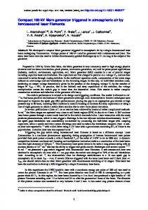
the discharge resistor earth switch is opened. The capacitors are charged at a maximum rate of 10 A on the low voltage, 230 V circuit, which corresponds to roughly 1 kV/s on the capacitors. While charging, the one-third voltage on each stage is continuously compared to ensure that the two stages are charging evenly, and charging is even between capacitors within each stage. If the voltages are seen to differ by more than 10%, charging is stopped, the capacitors are earthed, and a comprehensive check of equipment is performed. It is normal that the second stage one-third voltage lags behind the first stage, due to the charging time-constant through the water resistors. Once the desired charging voltage is reached, the charging supply is isolated and the experiment is triggered. If experiments are being completed exterior to the high voltage laboratory building, an air horn is used to warn bystanders that the likely explosion experiment is due. Upon experiment completion, the discharge resistor earth switch is then closed, and the capacitor voltages are observed to reduce to nearzero within about 3 seconds. The operators then leave the Faraday cage and approach the capacitor stack, maintaining a minimum approach distance of 1.5 m. The earthing levers and transformer earth stick are then applied. The earthing lever pistons are each visually checked to ensure they have made contact, and the equipment is then considered safe to touch. III. E XPERIMENTAL R ESULTS The two-stage Marx generator was commissioned by performing a series of EWs of increasing voltages. In each experiment, the capacitor voltages were closely monitored during charging to ensure that the series capacitors were sharing the charge evenly. Marx generator output voltages of 40 to 180 kV in steps of 20 kV were tested. The wire length chosen for each experiment was calculated to give an average electric field (AEF) of 6 kV/m wire, which produces reliable restrikes [5]. Enameled copper wire, 0.2 mm in diameter, was used for each experiment. Four shots were done in an attempt to produce the longest possible restrike from the equipment (fig. 4). The longest of these was 36 m using 180 kV; an AEF of 5.0 kV/m. To fit this length inside the laboratory, the wire was strung in a zig-zag configuration between two insulating ropes, spaced 6 m apart (fig. 5). An important finding from these experiments is that the voltage and current waveforms are very similar in shape to those recorded from EWs as short as 1 m [5], i.e. the mechanism is very scaleable. IV. C ONCLUSION A two-stage Marx generator was built for the purposes of performing long distance EW experiments. In all shots performed to date, the Marx generator has operated correctly. The measurement system and operating procedure has facilitated even and safe charging of the capacitor stages, and a safe and reliable means of de-energising and earthing the equipment.
Voltage (kV)
200 36.0 m, 180kV 31.5 m, 180kV 26.0 m, 160kV 22.5 m, 140kV
150 100 50 0
0
100
200 300 Time (μs)
400
500
400
500
(a) Voltage 10 Current (kA)
8 6 4 2 0
0
100
200 300 Time (μs)
(b) Current
Fig. 4: Voltage and current waveforms for 0.2 mm copper wire EWs of various lengths and voltages.
The spark gaps have neither self-triggered prematurely or failed to trigger when they should. The constructed energy supply has allowed researchers to investigate EWs up to 36 m long. This is believed to be the longest restriking EW ever published. Voltage and current waveforms from these experiments show strong similarities to the 1 - 9 m experiments previously peformed at the University of Canterbuy, showing that the mechanism is predictable and scaleable for longer lengths. Next, the design will be extended to incorporate a third stage, increasing the output voltage to 270 kV, and allowing EWs up to 54 m long. ACKNOWLEDGMENT The authors would like to acknowledge the support from J. Lawrence (Electric Power Engineering Centre) and technical support from J. Woudberg, K. Smart and D. Healy. R EFERENCES [1] W. G. Chace and H. K. Moore, Exploding wires. New York: Plenum Press, 1959. [2] A. E. Vlastos, “Restrike mechanisms of exploding wire discharges,” Journal of Applied Physics, vol. 39, no. 7, 1968. [3] B. K. Bhat and I. B. Jordan, “Explosion of bare and insulated copper wires,” Journal of Applied Physics, vol. 42, no. 2, p. 809, 1971. [4] M. J. Taylor, “Formation of plasma around wire fragments created by electrically exploded copper wire,” Journal of Physics D-Applied Physics, vol. 35, no. 7, pp. 700–709, 2002. [5] R. Sinton, R. van Herel, W. Enright, and P. Bodger, “Investigating longdistance exploding-wire restrike,” Plasma Science, IEEE Transactions on, vol. 38, no. 4, pp. 1015 –1018, april 2010. [6] R. Sinton, C. Hammond, W. Enright, and P. Bodger, “Generating high voltages with a plasma coil transformer,” in Techcon Asia Pacific, Sydney, 2009, pp. 211–219.
Fig. 5: A 36 m plasma path in the University of Canterbury High Voltage Laboratory.
[7] R. Sinton, R. van Herel, W. Enright, and P. Bodger, “Observations of the long distance exploding wire restrike mechanism,” Journal of Applied Physics, vol. 108, no. 5, p. 053304, 2010. [Online]. Available: http://link.aip.org/link/?JAP/108/053304/1 [8] D. Smith, W. Enright, and P. Bodger, “A test circuit for long distance directional plasma discharge using the exploding wire technique,” in 15th International Symposium on High Voltage Engineering (ISH), Ljubljana, Slovenia, 2007. [9] Standards Australia International Limited, AS60052: Voltage measurement by means of standard air gaps. Sydney: Standards Australia, 2005.