Nov 14, 2000 - The Software Engineering Laboratory (SEL) is currently engaged in a Methodology and Metrics ... Custom (new) software development.
A Matrix Approach to Software Process Definition
David Schultz, Judith Bachman, Linda Landis (CSC) Mike Stark, Sally Godfrey (GSFC) Maurizio Morisio (Univ. of Maryland)
Introduction The Software Engineering Laboratory (SEL) is currently engaged in a Methodology and Metrics program for the Information Systems Center (ISC) at Goddard Space Flight Center (GSFC). This paper addresses the Methodology portion of the program. The purpose of the Methodology effort is to assist a software team lead in selecting and tailoring a software development or maintenance process for a specific GSFC project. It is intended that this process will also be compliant with both ISO 9001 and the Software Engineering Institute’s Capability Maturity Model (CMM). Under the Methodology program, we have defined four standard ISO-compliant software processes for the ISC, and three tailoring criteria that team leads can use to categorize their projects. The team lead would select a process and appropriate tailoring factors, from which a software process tailored to the specific project could be generated. Our objective in the Methodology program is to present software process information in a structured fashion, to make it easy for a team lead to characterize the type of software engineering to be performed, and to apply tailoring parameters to search for an appropriate software process description. This will enable the team lead to follow a proven, effective software process and also satisfy NASA’s requirement for compliance with ISO 9001 and the anticipated requirement for CMM assessment. This work is also intended to support the deployment of sound software processes across the ISC.
Background The SEL is currently part of the Information Systems Center (ISC) at Goddard Space Flight Center (GSFC). The ISC was formed in December 1997, by reorganizing Government personnel, projects, and other resources from previously existing GSFC organizations. It comprises a number of application domains, and represents a conglomerate of different organizational cultures. In particular, the various predecessor organizations had employed a variety of approaches to software development. The evolution and adoption of a single organizational culture, and a single set of recognized software processes, is a challenge that ISC is presently facing. In early 1999, the SEL directors met with each of the eight branch heads within the ISC, to determine how the SEL could best serve their needs. The branch heads indicated that they would like to see the SEL package the proven software technology that it had developed over 25 years, so that it could be applied within the ISC. The Methodology study and the companion Metrics effort were two of the activities that resulted from these discussions. A key constraint that helped shape the new ISC culture was NASA’s decision to seek registration under the ISO 9000 suite of international standards. This decision increased the urgency for developing a standard software methodology that could be used consistently across the ISC. A brief note of explanation regarding the ISO 9000 suite may be in order. This suite of quality standards was first published in 1987, as a set of five standards, ISO 9000 through ISO 9004. These standards
A Maximum Approach
1
November 14, 2000
specified minimum requirements for a quality system. A revised version of the ISO 9000 suite was published in 1994 [1-5]. These standards, which were written primarily for the manufacturing community, also had a strong and immediate impact upon the software community. The standard most frequently cited for applicability in a software environment is ISO 9001. In response to a demand for guidance on how to apply ISO 9001 in a software environment, ISO developed ISO 9000-3, “Guidelines for the application of ISO 9001:1994 to the development, supply, installation and maintenance of computer software” [6]. A new revision of the ISO 9000 suite is scheduled for publication in late 2000, and is currently available in draft version. In June and July of 1999, GSFC conducted a series of internal audits against ISO 9001. A subsequent round of informal internal audits was conducted within the ISC around October 1999. In response to these internal audits, the SEL established a working group of ISC team leads to develop recommendations for bringing the ISC into conformance with ISO 9001. In November 1999, this SEL ISO team identified recommendations in the areas of both methodology and metrics. [7] The key recommendations of the ISC team leads that drove the present Methodology effort were as follows: • • • •
Define a template-based approach to documenting software methodology Organize information around developer activities, rather than around ISO concepts. Support multiple life cycle models, including the incremental build model and the spiral model Define methodology details separately for the following project types: • Custom (new) software development • Commercial off-the-shelf (COTS) or Government off-the-shelf (GOTS) based systems • High reuse projects—this includes maintenance projects and the use of product lines; the key element of a high reuse project is that the system architecture is almost completely defined at the beginning of the project.
A second constraint that is expected to affect the ISC culture is NASA’s recent decision to adopt the CMM. We first became aware in June of this year that CMM would need to be addressed. Once the GSFC CMM compliance requirements have been defined, we shall enhance the software processes to ensure that these requirements are satisfied.
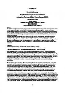
Description of the ISC Environment Figure 1[8] illustrates the diversity of the application domains within the ISC: embedded flight software, ground mission data systems, science data systems, advanced architectures, etc. The SEL sought to develop a small set of standard processes that could be used within these diverse application domains; it was not anticipated that a single process would be sufficient for the entire ISC. Even within a single branch of the ISC, the breadth of project types and the absence of a well-defined organizational culture would seem to preclude the imposition of a single standard software process across even one branch. We needed to identify common elements of the many processes already in use so as to converge on a small set of processes that could accommodate this diverse range of application domains.
A Maximum Approach
2
November 14, 2000
Embedded spacecraft, instrument and hardware component softwares; FSW testbeds
Real-time ground mission data systems for I&T and on-orbit ops (e.g., s/c command & control, launch and tracking services)
End-to-end data systems engineering of mission systems development activities.
Science data systems including data processing, archival, distribution, analysis & info man. Advanced concept development for archival, retrieval, display, dissemination of science data
Technology R&D focused on sys autonomy, scientific analysis tools, distributed computing architectures
Off-line mission data systems (e.g., Command man., s/c mission and science P&S, GN&C, NCC)
Tools and services in support of information management
Figure 1. ISC Application Domains
Technical Approach Previous Related Work The approach we used in this research derives from a three-level life cycle/method/technique hierarchy of software processes developed by Dr. Vic Basili [9]. Our work built on four predecessor SEL documents: • • • •
Manager’s Handbook [10] Recommended Approach to Software Development [11] NASA Software Management Guidebook [12] ISC Profile Report. [13]
The Recommended Approach and Manager's Handbook are "companion" documents that served for many years as the SEL's primary guidebooks for software development and management. Developed for the GSFC's Flight Dynamics Division and refined over 15 years in the SEL's "Experience Factory", the guidance provided in these documents remains sound engineering practice for much of the ISC. The activities listed in the current Methodology are consistent with those described in these two documents. The Methodology team borrowed from the NASA Software Engineering Program's Software Management Guidebook in defining the life cycles that are recommended for use with the current processes. The team used the ISC Profile Report to identify the key software domains within the Center and the associated software processes. These domains and processes were the starting point for the present research. It should be noted that we are using the term “software process” here as it is used within the ISC. We realize that, within the software engineering community, this term implies elements that are missing from our model, particularly synchronization of activities and entry/exit criteria. We have chosen to concentrate
A Maximum Approach
3
November 14, 2000
initially on the description of the software activities. Our intent is to develop a consistent set of methods, products, and techniques before we address the time-sequencing of these activities, and the associated synchronization and entry/exit concerns.
Research Activities We began by reviewing the ISC Profile Report to familiarize ourselves with our customer base. The Profile documents the SEL’s work in baselining the newly formed ISC organization, and it identifies the diversity of software projects and processes encompassed within the ISC. From the Profile we developed a preliminary grouping of the software engineering activities the Center conducts. We then collected and reviewed 16 existing ISC Product Plans written by ISC Team Leads to describe their respective projects and plans for the technical work and project management. We characterized each project by risk level, size of software team (which generally correlated with problem complexity), and software process. We also noted the software life cycle model that each project claimed to follow. The results are shown in Table 1 below. During the course of this project, the parameter initially labeled ‘risk’ evolved to ‘criticality of application’, and we also identified aggressiveness of development schedule as a key tailoring factor.
Table 1. Properties of the 16 Projects, as drawn from their Product Plans Project SIRTF IRAC
Methodology Waterfall
Process Type New Development with COTS New Development with COTS New Development New Development
Team Size 1
Schedule Aggressive
2
Normal
4 3
Normal “Liberal”
Risk Major risk is schedule “No major risks” Low risk Technical risk
DTAS
Spiral
GUMP Hitchhiker HCU FSW (Build 2) Hitchhiker Ground Data: ACE Hitchhiker Ground Data: Avionics Triana Ground Data
Structured Design Structured Design
New Development with some COTS New Development with some COTS High Reuse with COTS / GOTS High Reuse with COTS High Reuse with COTS / GOTS
7
Normal
Low risk
7
Normal
Technical risk
17
Aggressive
7
Aggressive
4-8
Aggressive
Multiple risks, esp. schedule Major risk is schedule Major risk is schedule
Triana Command / Data Handling Flight S/W Triana AOCS Flight Software EOS AM-1 FDS
Object Oriented Design; 2 releases Object Oriented Design with Incremental Build Incremental Build
10 - 12
Aggressive
Major risks are schedule and external deliveries
12
Aggressive
Incremental Build
New Development with some COTS; prototyping for verification of FDS design and operational concepts Test and maintenance only High Reuse
MAP
“Not applicable”
~6
Normal
Incremental Build
High Reuse
~7
Normal
Primary risk is schedule No risks identified No risks identified
HESSI ITOS Triana ITOS
Structured Design Structured Design Incremental Build
A Maximum Approach
4
November 14, 2000
Project ULDB ITOS
Methodology Incremental Build
Process Type High Reuse
Team Size ~1
Schedule Normal
NMP / EO-1 GS
(Multiple)
(very large)
Aggressive
HST Payload FSW
(Multiple)
New Development with COTS / GOTS Maintenance with extensive reengineering
(very large)
Normal
Risk No risks identified Major risk is schedule No major risks identified in Product Plan
There were other evolutionary changes in the parameters that eventually came to be known as ‘tailoring factors’. At one point, we had three categories for size (small, medium, and large) and three also for criticality (low, medium, and high). We soon determined that the processes would be essentially the same for small and medium sized teams, and for medium and high criticality projects. So we were able to drop the ‘medium’ categories as distinct drivers. In this manner, the tailoring factors evolved to their present set: team size, aggressiveness of schedule, and criticality of application. These tailoring factors, along with software process, became the taxonomy that we finally used. Our next steps were (1) to group the projects according to this classification to identify representative examples of each type of project, and (2) to meet with the software team leads of projects that were representative of the different categories in our taxonomy. We interviewed these team leads to clarify information in the Product Plans and to obtain additional details about the software processes they followed and the software life cycles that they employed. As a result of these interviews, we were able to converge on a set of software processes and software life cycles that typify the ISC environment. We determined that, despite variations in project terminology, and frequent use of COTS or GOTS, most ISC projects actually utilized one of four software processes: • • • •
New Development Maintenance High Reuse Prototyping.
The four software life cycle models that we identified were: • • • •
Waterfall Incremental Build Prototyping Spiral.
Software Process Description Using the SEL’s Recommended Approach as our starting point, we prepared an initial high-level description of a generic process for New Software Development. We then reviewed the 16 Product Plans and modified the generic process to reflect the processes that were actually being used within the ISC. We added the tailoring factors to reflect how the processes were actually adjusted for small teams, aggressive schedules, and high criticality. Finally, we developed separate initial, very concise process descriptions for Maintenance, High Reuse, and Prototyping. We organized these process descriptions in terms of ‘activity groups’, which is a concept first put forth in IEEE Std 1074-1998, “Standard for Developing Software Life Cycle Processes.” [14]. Activity groups are simply collections of activities that together accomplish a single well-defined function, and produce a single key product. For example, the Requirements activity group is comprised of activities such as
A Maximum Approach
5
November 14, 2000
defining software requirements, defining interface requirements, defining user interface requirements, developing derived requirements, and prioritizing requirements. Note that an activity group is not the same as a phase of the software development life cycle. In a software life cycle model, a phase refers to a period of time. For example, we can speak of the Implementation (sometimes called ‘Coding’) phase. Under the traditional waterfall model, this phase represents the period of time during which coding is performed. An activity group, on the other hand, is a collection of related activities, but there is no implication that these activities are performed within a specific period of time. The activities of a single activity group may be (and usually are) performed over multiple phases. The team lead can select a software life cycle model and use it to develop a time sequencing of the activities in the selected software process. We identified six activity groups that were uniform across all of our standard processes: Requirements, Design, Implementation, Test, Delivery & Support, and Cross-Cutting. Cross-Cutting activities are those activities that typically last throughout the entire software life cycle, such as task management, configuration management, quality assurance, document preparation, and training. Each of these activity groups comprises activities that, together, perform one or more specific functions. The activity groups and their respective functions are listed in Table 2. Table 2. Functions of the Six Activity Groups
Activity Group Requirements Design Implementation Test Delivery and Support Cross-Cutting
Functions Reach agreement with the customer on what the system is intended to accomplish Define the structure of the software system, and the function of each component Code and unit test each software module Perform the required levels of testing (e.g., build/release, system, and acceptance testing) to validate the software system Transition from development mode to operational mode Perform ongoing supporting activities that transcend individual activity groups, but are necessary for a successful project
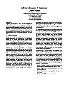
These activity groups fit into a four-level hierarchical model, as shown in Figure 2. We can view this hierarchy as a product line. That is to say, once we have selected a process type, identified the activities to be performed within each activity group, and defined the techniques to be followed, we have defined a software process tailored for a specific project. The two highest levels of the hierarchy, the software process type and the activity group, are invariant. A given ISC project will always follow one of four set processes (New Development, High Reuse, Maintenance, or Prototyping). Similarly, the selected process will always include six activity groups (Requirements, Design, Implementation, Test, Delivery and Support, and Cross-Cutting). At the third level, activities within the activity groups vary somewhat from one project to another. The techniques, on the lowest level, exhibit considerable variability from project to project.
A Maximum Approach
6
November 14, 2000
n Software
Software Process
Process Type
n Activity
Requirements Activities
Group
n Activity (Method)
Requirements Definition
Implementation Activities
Activity Group N
Review Code
Requirements Analysis
Activity n
Technique #2
n Technique
Technique #1
Walkthrough
Inspection
Formal Proof
Technique #n
Technique #1
Figure 2. Conceptual Methodology Model
Software Process Depiction Because we needed to specify the conditions under which certain activities would be performed, the process descriptions were phrased in structured language, similar to pseudocode or program design language (PDL), employing IF-THEN loops and similar constructs. For each actual step to be performed, a more detailed description was written. Later, to simplify the description, we used hyperlinks to connect the steps in the process descriptions with their respective detailed descriptions. It was thus possible to read the entire description of a process without being distracted by the details of the individual steps. The problem with this pseudocode representation was that it required one description for each software process and for each combination of project drivers. For example, we needed one description for the New Development process to be followed by a small team, on a low-criticality application, under an aggressive development schedule. We had a different description for the New Development process to be followed by a large team, on a high-criticality application, under a lenient development schedule. With three project drivers, and three values for two of them, two values for the third, and four process types, we would potentially need 3x3x2x4 = 72 separate process descriptions. It would have been difficult for us to compare these 72 process descriptions and identify the similarities and differences among them. This problem was resolved by switching to a matrix representation of the software processes. The pseudocode and the steps to be followed were identified in the left-hand column of the matrix. Each combination of tailoring factors (e.g., small team, aggressive schedule, critical application) was assigned one of the remaining columns, and an ‘X’ in that column was used to indicate whether each step of the process was to be performed for each type of project. (An example of a process matrix is contained in the Appendix.) Hyperlinks were used, as before, to provide links to the associated detailed information. Use of the matrix approach greatly simplified the development, presentation, and review of the process descriptions. The matrix approach also suggests an automated approach for future development: after the process type and drivers are selected, the activity list for the project could be generated automatically. The resulting “tailored” process could then be inserted or referenced in the appropriate portion of the Product Plan. The complete model for our approach to process tailoring is shown in Figure 3.
A Maximum Approach
7
November 14, 2000
ISC Process Definition Online Documentation Life Cycle
Processes
Activity Groups
Tailoring Factors
Project Inputs Ø Life Cycle Selection Ø Process Selection Ø Project-Unique Activities Selection Ø Tailoring Factors Selection
Tailoring to Project Product Plan
Tailored Process
Figure 3. Software Development Process Model
Verification and Validation In the course of this research, we used three levels of verification and validation to assess the suitability and usability of our work products: • • •
Review of work products within the Methodology working group Review of work products by working group of ISC team leads (see under ‘Background’ above) Occasional open forums (such as this Workshop) at which our work is presented.
As of this writing, these work products are: • • • • •
Hypertext overview of the process descriptions Set of definitions (based on IEEE standards and the CMM) that resolve standard software engineering and ISO terminology New Software Development Process matrix Maintenance Process matrix High Reuse Process matrix.
Using the matrix representation described above, each process provides for tailoring according to the following three tailoring factors: • • •
Team size (small/medium/large) Schedule (normal/aggressive) Criticality of application (Critical/non-critical).
The five work products have all passed through the first three levels of our V&V process. They have not yet been subjected to a fourth level of V&V: operational use of the processes by specific GSFC projects and teams. This activity will begin shortly, when actual software projects at GSFC begin using these processes.
A Maximum Approach
8
November 14, 2000
Lessons Learned Benefits of the Matrix Representation The matrix representation of a software process turned out to be a key factor in the success of the Methodology effort. The matrix made it easier for both developers and reviewers of a software process to compare the differences among different tailored versions—for example, to compare its use for small teams against large teams. The use of a table-like matrix also made it easier to deal with multiple levels of nested loops within the pseudocode representation of the processes.
Significance of the Software Life Cycle Model At the outset of this work, it was felt that both the application domain and the software life cycle model selected would be significant factors in the selection and tailoring of a software process. This turned out not to be the case. The software life cycle determines when and how often each activity will be performed, but has little impact on the detailed description of the activity. Similarly, the differences due to application domain become significant only at the Technique level of the hierarchy. Organizing the process descriptions by activity group allowed us to define processes in a manner that gave the projects greater flexibility in selecting their life cycles. By defining activity groups as distinct from life cycle phases, activities were not constrained to a particular phase and could be repeated as needed, both throughout the life cycle and across different application domains. For example, on a project that followed the Incremental Build life cycle model, the activities in the Implementation and Test activity groups could be repeated for every build. But this model makes no provision for iterations through the Requirements activities. Using activity groups, this is not a problem. Similarly, the Prototyping and Spiral models involve multiple iterations of the Requirements and Design activity groups; these, too, are easier to represent using activity groups.
Process Integration A lesson that we learned from the walkthroughs was that the Team Leads were searching for common elements among the processes. We, as process engineers, tended to focus on the differences between the processes. The Team Leads, however, as software developers, sought to reduce the number of differences among the processes. In particular, they suggested that the New Development and High Reuse processes could be merged into one. We are presently examining the implications of that proposal. It remains to be seen whether the processes will become more differentiated once software teams actually begin using these standard processes and providing operational feedback.
Future Work There are five areas of work that we hope to accomplish in the next two years: • • • • •
Expansion of our model to incorporate software products and tools, entry/exit criteria, and synchronization of activities Completion of the Prototyping Process Incorporation of operational feedback from actual GSFC projects that use the Processes Modification of our process model to address CMM Development of a web-based tool to support selection of a software process and the documentation of that process in a project’s Product Plan.
A Maximum Approach
9
November 14, 2000
Conclusion This work is significant for two reasons. First, we have been able to identify common elements in a complex environment of diverse application domains. This work provides a foundation on which we can develop appropriate techniques and product definitions that will allow the ISC to employ a consistent approach to software engineering development, while allowing optimization for a given project. This in turn will permit the collection of a consistent set of software metrics across a wide range of project types, and the continuous improvement and refinement of our software engineering knowledge base. Second, we have developed a simple tool (the matrix) for describing an important aspect of software processes. This tool greatly facilitated both the presentation and the review of the processes and their component activities. We expect that it will aid us in defining requirements for a more automated, webbased tool that will be useful to software team leads.
Acknowledgements The GSFC ISC Team Leads who developed the ISO Methodology and Metrics requirements, and who participated in the verification and validation of the Methodology work products, are listed below: Lisa Shears (Code 582) Scott Green, Terri Wood (Code 583) Karen Keadle-Calvert, Dan Mandl, Tom Taylor (Code 584) Jeff Lubelczyk (Code 586). The authors are grateful to Steve Condon, who serves as CSC team lead for this work and has participated in the Methodology team meetings from the inception of this project. Gary Meyers, of the GSFC ISO study team, participated in the Methodology work from its inception, and provided very helpful review comments at every stage. Mike Tilley, of Raytheon Corp., participated in this work as a representative of the Flight Software Branch (Code 582) of the ISC. The concept of a tabular representation of a software process was originally Mike Tilley’s; Gary Meyers proposed some very helpful modifications to Mike Tilley’s original representation.
A Maximum Approach
10
November 14, 2000
Appendix—Example of Software Process Matrix Legend:
X = Perform this activity O = This review or activity is optional but recommended Rv (in 1st column) = Review
F = Perform this review formally I = Perform this review informally * (in last column) = This activity is associated with an ISO "shall"
This font and shading indicates logic
This font and no shading is used for activities Critical Software
Non-Critical Software
ISO
X.0 Activity Group Normal Schedule
X.X Major Activity
Tailoring Drivers Small/ Medium Team
Activities
Large Team
Aggressive Schedule Small/ Medium Team
Large Team
Normal Schedule
Small/ Medium Team
Large Team
Aggressive Schedule Small/ Medium Team
Large Team
1.0 Requirements Activities 1.1 Software/System Concept Definition IF the system concept/architecture is already defined (i.e., because the software to be developed is part of a larger system or project such as a spacecraft or instrument), but the software concept/architecture is undefined, THEN Perform for all project types
Develop a software concept. ELSE (the system concept/architecture is undefined )
Perform for all project types
Develop a system and operations concept.
Rv
I
Hold A System Concept Review.(SCR) Hold a combined System Concept Review/System Requirements Review (SCR/SRR)
F
O I
F
O
* O
O
*
1.2 Requirements IF high-level requirements have not been provided, THEN Perform for all project types
Define high-level requirements. ENDIF
Always perform this activity
Derive detailed requirements and specifications.
1.3 COTS Evaluation and Selection IF using COTS/GOTS, THEN
A Maximum Approach
11
July 27, 2001
Legend:
X = Perform this activity O = This review or activity is optional but recommended Rv (in 1st column) = Review
F = Perform this review formally I = Perform this review informally * (in last column) = This activity is associated with an ISO "shall"
This font and shading indicates logic
This font and no shading is used for activities Critical Software
Non-Critical Software
ISO
X.0 Activity Group Normal Schedule
X.X Major Activity
Tailoring Drivers Small/ Medium Team
Activities
Large Team
Aggressive Schedule Small/ Medium Team
Large Team
Normal Schedule
Small/ Medium Team
Large Team
Determine the selection criteria for COTS/GOTS software.
Perform for all project types
Identify potential COTS/GOTS candidates.
Perform for all project types
X
Obtain demo versions and evaluate the candidate COTS/GOTS.
X
X
X
X
Aggressive Schedule Small/ Medium Team
Large Team
X
O
O
Perform for all project types
Select COTS/GOTS. Document the selection criteria and evaluation results.
X
X
X
X
X
X
O
X
Document the risks (cost, schedule, reliability, etc.) associated with use of the selected COTS/GOTS.
X
X
X
X
X
X
O
X
1.4 Requirements Documentation and Review Always perform this activity
Document requirements.
*
IF the software to be developed is part of a larger system or project (e.g., a spacecraft or instrument and high level requirements were provided), THEN
Rv
Conduct a Software Specifications Review (a.k.a. Software Requirements Review). (SSR)
I
F
O I
Conduct a combined Software Specifications Review/Preliminary Design Review (SSR/PDR)
O
F
* O
O
*
ELSE (a complete software system is to be developed and high level requirements were developed)
Rv
I
Conduct a System Requirements Review (SRR) Conduct a combined System Concept Review/System Requirements Review (SCR/SRR)
A Maximum Approach
12
F
O I
F
O
* O
O
*
July 27, 2001
Legend:
X = Perform this activity O = This review or activity is optional but recommended Rv (in 1st column) = Review
F = Perform this review formally I = Perform this review informally * (in last column) = This activity is associated with an ISO "shall"
This font and shading indicates logic
This font and no shading is used for activities Critical Software
Non-Critical Software
ISO
X.0 Activity Group Normal Schedule
X.X Major Activity
Tailoring Drivers Small/ Medium Team
Activities
Large Team
Aggressive Schedule Small/ Medium Team
Large Team
Normal Schedule
Small/ Medium Team
Large Team
Aggressive Schedule Small/ Medium Team
Large Team
2.0 Design Activities 2.1 Procurement IF hardware, software, and/or firmware must be procured, THEN Perform for all project types
Procure and install hardware, software, and firmware.
2.2 Prototyping IF there are significant technical risks (e.g. unfamiliar technology, performance/reliability issues, undefined user interface), THEN Perform for all project types
Perform prototyping to reduce risks.
X
Document the prototyping effort.
X
X
X
X
* X
O
X
*
2.3 Preliminary Design IF system architecture does not already exist, THEN Prepare high-level architecture diagrams.
Perform for all project types
*
Always perform this activity
*
FOR all new custom software and glue ware, DO Design high-level functions or specifications. Conduct walkthroughs and/or inspections of the high-level functions/specifications.
X
X
I
F
X
X
O
O
O
O
O
O
*
O
O
*
IF the software is part of a larger system, THEN
Rv
Conduct a Preliminary Design Review. (SSR was held) Conduct a combined Software Specifications and Preliminary Design Review. (SSR/PDR)
I
F
ELSE
A Maximum Approach
13
July 27, 2001
Legend:
X = Perform this activity O = This review or activity is optional but recommended Rv (in 1st column) = Review
F = Perform this review formally I = Perform this review informally * (in last column) = This activity is associated with an ISO "shall"
This font and shading indicates logic
This font and no shading is used for activities Critical Software
Non-Critical Software
ISO
X.0 Activity Group Normal Schedule
X.X Major Activity
Tailoring Drivers
Activities
Rv
Conduct a Preliminary Design Review. (PDR)
Small/ Medium Team
Large Team
I
F
Aggressive Schedule Small/ Medium Team
Small/ Medium Team
Large Team
Aggressive Schedule Small/ Medium Team
Large Team
* I
Conduct a combined Preliminary Design Review /Critical Design Review. (PDR/CDR)
Large Team
Normal Schedule
F
O
O
O
O
*
ENDIF Always perform this activity
Document the preliminary design.
*
2.4 Detailed Design FOR all custom software and glue ware, DO Develop the detailed design.
Always perform this activity
Conduct walkthroughs and/or/inspections of the detailed design.
Always perform this activity
*
IF PDR was held, THEN
Rv
I
Conduct a Critical Design Review.(CDR)
F
I
F
I
F
I
F
*
I
F
I
F
I
F
*
ELSE (PDR was not held)
Rv
Conduct a combined Preliminary Design Review/Critical Design Review (PDR/CDR) ENDIF
Always perform this activity
Document the detailed design.
A Maximum Approach
14
*
July 27, 2001
References [1] ISO 9000-1:1994, “Quality Management and Quality Assurance Standards—Guidelines for Selection and Use” [2] ISO 9001:1994, “Quality Systems—Model for Quality Assurance in Design, Development, Production, Installation, and Servicing” [3] ISO 9002:1994, “Quality Systems—Model for Quality Assurance in Production, Installation, and Servicing” [4] ISO 9003:1994, “Quality Systems—Model for Quality Assurance in Final Inspection and Test” [5] ISO 9004-1:1994, “Quality Management and Quality System Elements—Guidelines” [6] ISO/DIS 9000-3, “Guidelines for the application of ISO 9001 to the development, supply, and maintenance of computer software” [7] M. Stark, L. Shears, S. Godfrey, S. Green, T. Wood, D. Mandl, K. Keadle-Calvert, T. Taylor, J. Lubelczyk, “Recommendations for Methodology and Metrics: Implementing ISO9000 in the ISC,” GSFC white paper, November 1999 [8] Howard Kea, “ISC Overview Paper for Software Engineering,” presented at the 23rd Annual Software Engineering Workshop, GSFC, Greenbelt, MD, December 1998 [9] “Evolving and Packaging Reading Technologies,” Victor R. Basili, Journal of Systems Software, 1997, Volume 38, pp. 3-12. [10] “Manager’s Handbook for Software Development, Revision 1,” SEL-84-101, Software Engineering Laboratory, November 1990 [11] “Recommended Approach to Software Development, Revision 3,” SEL-81-305, Software Engineering Laboratory, June 1992 [12] “Software Management Guidebook,” NASA-GB-001-96, National Aeronautics and Space Administration, November 1996 [13] “Profile of Software at the Information Systems Center,” SEL-99-001, Software Engineering Laboratory, November 1999 [14] “Standard for Developing Software Life Cycle Processes, IEEE Std 1074-1998, Institute of Electrical and Electronics Engineers, December 1998 [15] Scott Henninger, “Using Software Process to Support Learning Software Organizations,” presented at the 25th Annual Software Engineering Workshop, GSFC, Greenbelt, MD, November 2000
A Maximum Approach
15
July 27, 2001