KSCE Journal of Civil Engineering (2013) 17(7):1644-1653 Copyright ⓒ2013 Korean Society of Civil Engineers DOI 10.1007/s12205-013-0108-4
Information Technology
pISSN 1226-7988, eISSN 1976-3808 www.springer.com/12205
A MEMS-based Commutation Module with Vibration Sensor for Wireless Sensor Network-based Tunnel-blasting Monitoring Jungyeol Kim*, Soonwook Kwon**, Seunghee Park***, and Youngsuk Kim**** Received Feburary 27, 2012/Accepted January 21, 2013
··································································································································································································································
Abstract The authors have developed a tiny, low-cost accelerometer that utilizesa semiconductor fabrication technology called MEMS (Micro Electro-mechanical System), for building a sensor network which would have a large quantity of such sensors deployed all over the host structure to be monitored. Due to the small dimension and extremely low power consumption, the sensor device is wellsuited for such networks, where the supply of external power is very constrained. The authors have designed both a sensor device, and a sensor module having wireless communication capability built around it, and tested them in real-world tunnels, as well as in test labs. The test results showed that our prototype performed adequately for its intended use. Keywords: vibration sensor, tunnel, structural health monitoring, MEMS, sensor network ··································································································································································································································
1. Introduction Blasting work using explosives produces extensive noise and vibration that can negatively affect nearby residents and facilities. For that reason, many jurisdictional authorities require monitoring of such works. To monitor the effects of the explosion, the vibration of bedrocks and artificial structures in the nearby area is measured, and the measurement value is analyzed for assessment of possible effects from the explosion. Currently such measurement job relies on very expensive sensors, making it uneconomical when considered for building a sensor network. Our research that is described in this paper has two goals: first, to develop an inexpensiveyetaccurate accelerometer based on MEMS (Micro Electro-Mechanical Systems) technology for small dimension and cost reduction; second, to develop a wireless communication module for easier deployment of the sensor network based on our MEMS sensors.However, the communication module can also be configured for other sensor types. This paper is structured as follows: first, it briefly reviews the measuring process of tunnels, and the available technology for tunnel measurement-specifically for wireless sensor networks, and the current state-of-the-art regarding sensor technology suited toa network approach, featuring low power consumption, small physical dimension, etc. Second, the authors describe a
technological overview, with test result of our wireless communication node designed for the sensor network monitoring vibration of a tunnel. Third, the authors present a sensor device designed by the authors using Micro Electromechanical System (MEMS) technology, together with test results of our prototype. Finally, alternative power supply methodology, which has been the subject of active research, is discussed, together with preliminary testing of available technologies.
2. Analysis of (Tunnel) Measuring Process To provide a technical review of current practices in measuring tunnels, the authors collected various manuals and guides for measuring tunnels from published sources, such as the national standard specification of civil engineering projects, Korean Standard for testing and measurement, tunneling manuals from several private firms, etc. The authors also tested existing technological elements for measuring (Fig. 1). The elements were evaluated using the following criteria: application area, sensor type (conventional versus MEMS), communication method (by-wire vs. wireless), and measuring method (dynamic vs. static). Although reliable and precise, existing sensor technologies revealed shortcomings when it came to the communication criterion, as they demonstrated inconvenience, due to cable connection
*Senior Researcher, Korea Institute of Construction Technology, Ilsan 411-701, Korea (E-mail:
[email protected]) **Member, Associate Professor, School of Civil, Architectural, and Environmental Engineering, Sungkyunkwan University, Suwon 440-746, Korea (Corresponding Author, E-mail:
[email protected]) ***Member, Assistant Professor, School of Civil, Architectural, and Environmental Engineering, Sungkyunkwan University, Suwon 440-746, Korea (E-mail:
[email protected]) ****Member, Professor, Dept. of Architectural Engineering, Inha University, Incheon 402-751, Korea (E-mail:
[email protected]) − 1644 −
A MEMS-based Commutation Module with Vibration Sensor for Wireless Sensor Network-based Tunnel-blasting Monitoring
3. Review of State-of-the-art Researches Even for MEMS, there are many technologies that can be used for making vibration sensors. Available MEMS sensors for measuring acceleration, force and deformation include piezoelectric, piezo-resistive, capacitive, resonance, optical and magnetic.The authors surveyed research papers published in international journals and conference proceedings from 2005 onwards that cover various MEMS sensors, and the wireless sensor networks that employ them. The authors also reviewed some non-MEMS sensor technologies applied to health monitoring of construction structures, including tunnels (Table 1). For the sensor technologies, the authors used performance criteria (e.g., accuracy, measurable range, etc.) for making a comparison between them. Many of the currently available MEMS sensors are based on the electro-mechanical type, which measures the varying capacitance of a moving mass; to increase sensitivity, the mass is shaped like a comb. Such sensors can have various application areas other than accelerometers, such as inclination sensors (Yu et al., 2009), etc. As their comb-like shape is very vulnerable to external
Fig. 1. Test of Existing Sensor Technology
problems. The test led us to decide that all sensors used in our system must utilize wireless communication (Zigbee) for transmitting sensor readings; also, for the sensors, existing sensors were not to be replaced with MEMS counterparts, if they offered better results than the newer, less matured MEMS breed.
Table 1. Review of Sensor Technologies for the Tunnel Measurement System Source
Tech highlights
What is sensed
Alfado, Weiss et al. (2009)
Bone-implantable multi-axis CMOS-MEMS stress sensor
Stress (force)
Azevedo et al. (2007)
Silicon carbide (SiC) MEMS resonant strain sensor-silicon comb-driven double-ended tuning fork (CDDETF) type
Kon and Horowitz (2008)
High-res MEMS piezoelectric strain sensor using Zinc Oxide (ZnO) layer
Yu et al. (2009)
Wireless inclination sensor system, which uses VTI’s SCA100T MEMS inclinometer
Ioppolo, Ötügen et al. (2008, 2009)
Kang, Schulz et al. (2006)
Leng et al. (2005)
Micro-optical wall shear stress sensor using whispering gallery mode (WGM) resonator - optical MEMS Polymer-reinforced carbon nano-tube (CNT) strain sensor - a resistive type electrical strain sensor Fiber optic sensors using extrinsic Fabry-Perot interferometric sensors and fiber Bragg grating sensors (as a part of a fiber-optic sensor network)
Vol. 17, No. 7 / November 2013
Sensor type
Sensor performance Measurable range Accuracy
Power characteristics 3.3v, 775 uW / measurement
Piezo-resistive
~ 250 kPa
100 Pa, w/ 1Hz interval, 15.2dB SNR
Strain (deformation) measuring resonant frequency, which varies over applied strain
MechanicalCapacitive
Survivable up to 10000 g acceleration
Sensitivity: 66 Hz/ue, Resolution: 0.11ue over 10-20k Hz, -109 dBc/Hz noise floor
N/A
Strain (deformation)
Piezoresistive
N/A
40.3 ne at 2140 Hz, 28.7 ne at 10 KHz
N/A
Inclination
Mechanicalcapacitive, using over-damped elements to avoid vibration
±30 deg (SCA100T-D01), ±90 deg (SCA100T-D02), Survivable up to 20000G
Resolution: 0.0025 deg at 10 Hz Sensitivity: 70 mV/deg (D01), 35 mV/deg (D02)
5v
Shear stress
Optical - using non moving deformation of light-transmitting material, sensing its optical resonance
Up to 1 kHz
0.01Pa
N/A
Strain
Resistive
±6000 micro-strain
N/A
20v
optical
±500 micro-strain, when up to 14 MPa force is applied
N/A
N/A
strain
− 1645 −
Jungyeol Kim, Soonwook Kwon, Seunghee Park, and Youngsuk Kim
shock, the capacitive-type sensors have inherent drawback in terms of durability, which have been addressed in (Azevedo et al., 2007). Another type of MEMS sensor uses the piezo-resistive property of a metal oxide layer. For such sensors, Kon et al. (2008) demonstrated a simply shaped (compared to the comb-shaped) piezo-resistive sensor that was sensitive to higher frequency vibration. Alfado et al. (2009) took a similar approach, which implemented multi-axis sensors on a single device. In general, those sensors are able to measure physical deformation (i.e., not accompanying movement) that should be limited to a microscopic scale. An optical method is seen in two series of studies (Ioppolo et al., 2008; Ioppolo et al., 2009), which measure the varying optical resonance of a light-transmitting mass caused by its deformation, thus sensing strain. The varying intensity of a laser beam transmitted through an optical fiber is also used for a strain sensor (Leng et al., 2006), though optical fiber is vulnerable to damage caused by external force, so a protection mechanism is necessary. Though not classified as MEMS, Kang et al. (2006) showed that Carbon Nano-Tube (CNT) can be used for sensing external force, which can be embedded into the building structure. Although there are numerous methods known for MEMS sensors, sensing movement (and thus, acceleration) is best implemented with a varying-capacitance type sensor; however, there are several drawbacks if we consider such sensors for sensing vibration: first, the sensor is vulnerable to excessive shock, which can be caused from blast, so it must be designed for durability. Second, a durable design may decrease the sensitivity of the sensor when measuring smaller movement; to address this issue, the authors designed a cantilever-type opto-mechanical sensor that provides both durability and sensitivity.
Fig. 2. Design Sketch of Our Single-axis MEMS Accelerometer
Fig. 3. ANSYS Simulation of the MEMS Sensor Design: (a) Stress Analysis for the Mass and the Spring, (b) Analysis of Its First-order Mode of Resonance (999 Hz)
4. Development of MEMS-based Vibration Sensor The authors developed two different MEMS sensor types-a conventional, comb-type, electro-mechanical sensor, and a cantilever-type opto-mechanical one. The latter was designed after two iterations of the former studies (Kim et al., 2005; Kwon et al., 2006), because our electro-mechanical design didn’t achieve sufficient performance for measuring micro-acceleration. The developmental details of those sensor types are described in the following sections. 4.1 Design and Fabrication The authorsfirst designed a single axis MEMS accelerometer capable of sensing planar acceleration. It is a differential type, using comb-shaped electrodes for applying the area-variation method. The mass is suspended with a folded-beam spring, which is illustrated in Fig. 2. Our design was evaluated with ANSYS software for stresses applied to the spring and the pendulum mass, and the resonance mode of the sensor as well (Fig. 3). The result
Fig. 4. Scan Electron Microscope (SEM) Image of Our MEMS Device
was used for determination of the size of the micro-components and operational frequency range of the sensor, respectively. The authors fabricated our sensors several times, as we revised the design. Later revisions have addressed performance issues in earlier ones, such as linearity, sensitivity, noise. For the last (fourth) revision, three-axis vibration sensors utilizing three discrete single-axis sensors were developed, accompanied by improved circuitry and communication performance; as a result, the authors had a mass of 120 µg, with springs whose dimensionsare 450 µm × 4 µm, with maximum detectable frequency of 1 kHz. Fig. 4 shows a picture of our sensor sample taken with a Scanning Electron Microscope (SEM).
− 1646 −
KSCE Journal of Civil Engineering
A MEMS-based Commutation Module with Vibration Sensor for Wireless Sensor Network-based Tunnel-blasting Monitoring
Fig. 5. 3-axis Vibration Sensor Module Built with Three MEMS Accelerometers
Fig. 6. A Wireless Communication Module, with Open Protective Housing
4.2 Making a 3-axis Vibration Sensor and a Communication Module Using the single axis MEMS accelerometer we developed, the authors built a 3-axis vibration sensor, by combining three sensor modules with newly-developed circuitry (Fig. 5). One of the issues in combining the sensors was accommodating the three sensor channels into the limited bandwidth of the communication module. A communication module consists of multiple transmitters embedded in MEMS vibration sensors, and a receiver that collects data from the transmitters. Both transmitters and the receiver use Zigbee communication protocol (based on IEEE 802.15.4), which enables error-free data transfer from multiple transmitters over the 2.4 GHz radio band. Performance of a wireless communication module is a constraining factor for sampling rate of an individual sensor, number of available transmitters, power consumption, etc. To extract maximum performance from the communication module, each transmitter node was set to send data in a 200 ms interval, with the help of internal memory for buffering sensor readings during the interval. Also, the sensor was set to measure at least 300 Hz of vibration frequency (i.e., sampling rate), as the burst-mode data transmission used in our system enabled us to squeeze out more bandwidth by reducing overheads in the data packet-which, at a 300 Hz sampling rate, allowed simultaneous transmission of ten single-axis sensor readings, or three triple-axis sensor readings. For operation of overall sensor network (dubbed as USN, ubiquitous sensor network), the authors developed internal measuring software and network software on TinyOS 2.0, which also contributed to low-power performance. Our wireless data transmitter consists of a sensor module (which itself consists of a MEMS sensor and a driver circuitry), a signal processing circuitry, a Zigbee communication module and a power supply. Fig. 6 shows an actual transmitter module. Input voltage from the MEMS sensor (i.e., sensor output signal) is amplified first, then is fed to an embedded low-pass filter for removing noise, An embedded analog-to-digital converter generates
a stream of 16-bit word data from the amplified, noise-free analog signal. The data stream is then to be transmitted via a Zigbee communication module (which is built around a CC2420 chip from Texas Instruments). The module is configured to buffer the data in its embedded memory for allowing burst-mode transmission, which allows the achieving of a 300 Hz sampling rate over the rathernarrow bandwidth of Zigbee. A receiver module communicates with multiple sensor modules over 2.4 GHz Zigbee protocol. When it receives data from the sensor modules, it passes the collected data to a host computer via USB. A data receiver can be connected up to three transmitters, each of which has three data channels assigned for X, Y, and Z axes.
Vol. 17, No. 7 / November 2013
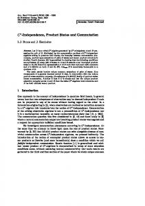
4.3 Laboratory and Field Tests of the Sensor Module The authors analyzed performance of our prototype sensor by comparing its performance with existing sensors. For the comparison, a commercial ICP accelerometer (capable of measuring -0.5 g to +0.5 g) and a MEMS accelerometer manufactured by Analog Devices (capable of measuring -1.7g to +1.7g) were
Fig. 7. Test Result: Triangular Dots Show Readings from Our Prototype, Square Dots Show Readings from a Commercial MEMS Sensor (for Comparison), Small Diamond Dots Show Readings from the ICP Sensor (as a Reference)
− 1647 −
Jungyeol Kim, Soonwook Kwon, Seunghee Park, and Youngsuk Kim
Fig. 8. The Full Comparison of Commercial MEMS Sensor and MEMS Prototype
MEMS sensor was 10.1%. Both MEMS sensors behaved worse as the acceleration increased, yet the commercial sensor had more error than ours. On the other hand, those MEMS sensors showed difficulty in measuring acceleration less than 0.1 g, due to their inherent noise level.The full comparison of commercial MEMS sensor and our prototype in Fig. 8 shows similar trends among them. The authors conducted a test of our prototype sensor module at an actual blasting site located in Daesan, South Korea (see Fig. 9 for pictures of the actual test scene). Sensor device and its communication module showed their performance and robustness in the actual site.
5. Opto-mechanical Vibration Sensor Design In order to improve our MEMS sensor, the authors iterated our design and fabrication effortsfive times. For the first three iterations, the authors tried to improve various performance aspects, such as linearity, sensitivity, and noise rejection.For the fourth iteration, the authors developed a 3-axis accelerometer, utilizing our single-axis sensor devices. For the fifth and final iteration, the authors designed a new sensor type for measuring micro acceleration less than 100 mg, which was not possible with our varying capacitance type design, due to higher noise floor. Such a limit was considered unbeatable for that type of MEMS accelerometers, including commercial devices.
Fig. 9. Snapshots of the Testing of the Sensor Module at an Actual Blasting Site
used. The ICP sensor was selected as a reference, because it has a very low noise level, and is very sensitive. For the test, the authors installed these sensors on the same elastomeric test bed; then, the authors produced artificial waves, having variable magnitudes ranging from 0.5 mm up to 48 mm, for measurement. Fig. 7 illustrates the test result. Since ICP sensors cannot measure accelerations greater than ±0.5 g, only two MEMS sensors were used for measurements over that value. From the test result, it is shown that the measurement value from our prototype is closer to the reference value (from the ICP sensor) than the commercial MEMS sensor. The average error ratio of our prototype was 8.2%, while that of the commercial
5.1 Designing the Optic-MEMS Accelerometer For measuring the micro acceleration (< 100 mg), the authors developed an opto-MEMS type sensor design. This sensor design is coupled with a laser displacement-measurement module that allows measurementof the actual vibration. The laser measurement module has a simple construction, is less prone to noise issues, and is very precise, which has been proven in various applications. Cost reduction is also viable, by using LED light sources. For our prototype, the module consisted of a laser, a photo diode, signal processing circuitry and power supply. The authors used a P15 laser module from 3 Laser Tech Inc., of output power 35 mW at 635 nm single wavelength. The diameter of the beam output was adjusted to 200 µm, using an optical lens. The lightsensing photodiode was a Hamamatsu Model S3979, a photo diode for single-axis displacement measurement; its nominal resolution of displacement is 0.1 µm, and maximum sensitivity is obtained at 920 µm wavelength. At 635 nm, its performance degradation is negligible, and even shows better resistance to temperature changes, according to the datasheet. The power supply and signal processing circuitry were connected to the laser and the photo diode respectively. Fig. 10 shows a simple diagram of the signal processing module. In our optical sensor module, the laser beam is projected to a MEMS-fabricated cantilever, which will create movement of the reflected beam due to the vibrating cantilever, which is captured by the photo diode, and is converted to electronic signals to be
− 1648 −
KSCE Journal of Civil Engineering
A MEMS-based Commutation Module with Vibration Sensor for Wireless Sensor Network-based Tunnel-blasting Monitoring
Fig. 10. Circuit Diagram of the Signal Processing Module
shape and material. It was necessary to analyze the shape of our accelerometer mass, in order to decide the measurable frequency range. Since our accelerometer is cantilever-shaped, the authors used a simple beam-like shape for modeling our accelerometer to simplify the analysis. Using the simple beam model, its shape is determined with three parameters of length(L), width(W), and thickness (T). For such a beam-shaped elastic structure, Eq. (1) shows how the resonant frequency is related to other variables.
Fig. 11. Concept of the Optical Vibration Measurement Module
π K Fr = --- ----2 M
(1)
Fr = Resonant frequency K = Elasticity coefficient M = Mass From Eq. (1), it is revealed that a higher elasticity coefficient and lower mass is necessary for achieving a higher resonant frequency. For the elasticity coefficient (K) and mass (M), the following Equations are known: t 3 K = E ⋅ W ⋅ ⎛ ---⎞ ⎝ L⎠
(2)
E = Young’s Modulus L = Length t = Thickness W = Width M = ρ⋅L⋅W⋅t
(3)
r = Density Fig. 12. Cut-away View of the MEMS-based Opto-mechanical Vibration Sensor
processed by downstream modules. Fig. 11 is a diagram of the entire optical measurement module, and Fig. 12 shows the crosssection diagram of the module. 5.2 Design Variables of the Accelerometer Three variables significantly affect the resolution of the MEMS accelerometer: These are resonant frequency, vertical displacement, and linearity. 5.2.1 Resonant Frequency Resonant frequency of a vibrating object is determined by its Vol. 17, No. 7 / November 2013
From Eqs. (2) and (3), the following Equation regarding the resonant frequency can be derived: 1 E t Fr = ------ --- ⎛ -----⎞ 2π ρ ⎝ L2⎠
(4)
From Eq. (4), it can be seen that the resonant frequency of a beam-shaped elastic object is determined by its thickness (t) and length(L). Therefore, such an object should have a high elastic coefficient with low mass, if it needs a high resonant frequency. 5.2.2 Vertical Displacement Vertical displacement of an accelerometer is caused by elastic movement; therefore, the following Equation can also be applied:
− 1649 −
Jungyeol Kim, Soonwook Kwon, Seunghee Park, and Youngsuk Kim
F = K⋅x
(5)
F = Driving force K = Elasticity coefficient x = Vertical displacement This implies that lower elasticity coefficient and higher driving force are necessary for achieving more vertical movement, and that the shape of the sensor should be designed to lower its own elasticity coefficient for sufficient displacement. 5.2.3 Linearity Although an elastic mass deforms in a linear manner, the frequency of the driving force adversely affects damping of the movement. This issue is discussed in a later chapter. 5.2.4 Other Design Factors Minimum area Since the displacement of the accelerometer is measured optically using a laser, it should have a reflective surface whose area is sufficient for such measurement. Since we used a circular laser beam whose diameter is 200 µm, the reflective surface should be larger than that. Q-factor Q-factor represents the response of a resonant mass inside a fluid. To increase the factor, the area must be small.
Fig. 13. Shape of the Accelerometer Mass - Cantilever ST Type
●
●
5.3 Shape of High-resolution Accelerometer Our MEMS accelerometer is made of Silicon with 50 µm thickness due to the fabrication process. It is designed to satisfy two conflicting goals: to have a large reflective area, while having minimal overall size for faster response and better sensitivity. Figs. 13 and 14 show two shapes we have designed. The DT type cantilever (which has dual spring beams) is designed to have a high Q-factor, by reducing the area of the springs while maintaining its width; the ST type, which has a large single spring beam, tries to minimize the loss of Q-factor, by reducing the sensor area while keeping its displacement high.
Fig. 14. Shape of the Accelerometer Mass - Cantilever DT Type
5.4 Optimization of the Sensor Design As demonstrated in Eqs. (1) and (5), the accelerometer mass must have both a higher resonant frequency and a larger vertical displacement; the latter property requires lower elasticity, whereas the former requires a higher one. To choose the optimal design parameter, the authors conducted numerical analysis on the sensor shape against its Length(L), Width(W), resonant frequency and vertical displacement (design variables). Fig. 15 illustrates the relationship between design variables and their result (resonance/deformation). The authors used pre-determined design variables, such as minimum width, target resonant frequency,
Fig. 15. Numerical Analysis of Bending Mode with Respect to Shape − 1650 −
KSCE Journal of Civil Engineering
A MEMS-based Commutation Module with Vibration Sensor for Wireless Sensor Network-based Tunnel-blasting Monitoring
Table 2. Five Design Candidates for Our Opto-mechanical Sensor Mass (Unit: µm) Type
Lspr 3000 3000 5000 5000 5000
STF1 STF2 STF3 STF4 STF5
Wspr 1000 1000 1500 1500 1500
Lsei 500 1000 1000 1000 1500
Wsei 1000 1000 1000 1500 1500
Fig. 16. FEM Analysis of Five Design Candidates (Example, STF2) - 0.1 mg is Applied: (a) Vertical Displacement, (b) Resonant Mode 1, (c) Resonant Mode 2
target displacement, etc., then ran the analysis program, using MATLAB. 5.5 Iteration of the Initial Sensor Design The authors chose the ST type cantilever over the DT type, because the former allowed a higher measurable frequency. Based on it, the authors designed five different shapes that were subject to finite element analysis for their dynamic behavior (see Table 2 for detailed shape parameters of those sensors). The analysis result shows that they generate displacements of 26 µm ~122 µm when 0.1 mg vibration is applied; for the secondary resonant mode, all of them are above 250 Hz, which is our design goal for maximum measurable frequency (see Fig. 16). 5.6 Fabrication of the Sensor Our accelerometer is fabricated on a 4 inch SOI (Silicon on Insulator) wafer. There are several issues to consider when designing the sensor layout on wafer: we want to harvest as many sensors as possible from a single wafer, yet spacing between individual sensors must be arranged so that the completed sensors can be
Fig. 17. Photo Mask Layout of Our Accelerometer Vol. 17, No. 7 / November 2013
detached easily from the wafer. Also, the fabrication process needs to be carefully planned, so that they can be produced economically. The layout design also features supporting structures, which prevent the fabricated sensors from damage when various forces are applied to the wafer during the fabrication process. To remove the remaining area, a deep silicon etching process is used. Fig. 17 shows the photomask layout of the wafer. 5.7 Evaluation To evaluate our MEMS-based optical sensor, the authors measured the same vibration using two sensors - a reference sensor (Wilcoxon Research 731A, Fig. 18), and our prototype. The readings from both sensors were fed to a Dacron Photon 24bit dynamic signal analyzer (Fig. 19) for further analysis. To reduce difference in attenuation of the input vibration, both sensors were located as close to each other as possible, and their readings were time-synchronized. The g-value of the reference sensor was calculated using a linear conversion equation provided by the sensor manufacturer, whereas our module didn’t apply any conversion for linearity compensation. From the test result, among five design alternatives, the STF3 model was closest to the reference sensor with respect to its
Fig. 18. Wincoxon Resarch 731A Vibration Sensor and Its Specification − 1651 −
Jungyeol Kim, Soonwook Kwon, Seunghee Park, and Youngsuk Kim
500 mg, it was 4.52%.
6. Conclusions For development of a new breed of sensors, the authors investigated two different sensor types, both of which were based on MEMS technology. The first type uses a comb-shaped suspended mass that causes varying capacitance while the mass is moving, due to external vibration; the second type, our latest iteration, combined optical measurement using reflectors mounted on a MEMS-fabricated cantilever, which enhanced sensitivity in small-acceleration, e.g., less than 100 mg. Basically, the result of this research can be applied to the ground vibration monitoring due to blasting for tunnel construction. It can measure vibration and acceleration of the blasting, and its data can be utilized for the analysis of nearby ground condition. Also, the sensor module can be used for the impact analysis of buildings and civil infrastructures close to the blasting point. Furthermore, with the ease and speed of its deployment, the sensor module can be employed for the emergency vibration or acceleration measurement of any artificial structure. However, the sensor module has several limitations. The first limitation is its power consumption. Although the prototype sensor module requires lower power than conventional sensors and it can be operated several days with commercial batteries, its power consumption still needs to be optimized for the long-term battery operation. Solar cell or fuel cell can be an alternative power source of this module at this point. The second limitation is its size. The size and the arrangement of sensor jig, circuit, and case are not optimized as other commercialized sensors. These limitations should be overcome for the actual use of this module during the commercialized process in the future.
Fig. 19. Dacon Photon 24-bit Dynamic Signal Analyzer
Fig. 20. Test Setup
Acknowledgements This study was conducted as a base project of Korea Institute of Construction Technology under the support of Ministry of Knowledge Economy (Project Code: KICT 2009-061).
References Fig. 21. Comparison of the Sensor Output between the Reference Sensor (Orange Circle) and Our Sensor (Blue Dot)
dynamic characteristics. STF1 and STF2 fell short of sensitivity, whereas STF4 and STF5 didn’t behave well in terms of signal attenuation. Fig. 20 was taken from the test scene. After calibrating our sensor module, the authors acquired the final measurement values from our module, which is shown in Fig. 21. The graph shows variable magnitude of the test vibration, up to 500 mg. For the 0~100 mg range, the standard deviation of the difference with respect to the reference sensor was 2.77, showing that our sensor was able to measure reliably in that range; for 100 mg~
Alfado, F., Weiss, L., Campbell, P., Miller, M., and Fedder, G. K. (2009). “Design of a multi-axis MEMS sensor for intraosseous bone stress monitoring.” J. Micromech. Microeng., Vol. 19, No. 8, 805016 pp. 1-13. Azevedo, R. G., Jones, D. G., Jog, A. V., Jamshidi, B., Myers, D. R., Chen, L., Xiao-An, F., Mehregany, M., Wijesundara, M. B. J., and Pisano, A. P. (2007). “A SiC MEMS resonant strain sensor for harsh environment applications.” IEEE Sensors Journal, Vol. 7, No. 4, pp. 568-576. Ioppolo, T., Ayaz, U. K., Ötügen, M. V., and Sheverev, V. (2008). “A micro-optical wall shear stress sensor concept based on whispering gallery mode resonators.” 46th AIAA Aerospace Sciences Meeting and Exhibit, Reno Nevada, USA. Ioppolo, T., Ayaz, U. K., Ötügen, M. V., and Sheverev, V. (2009). “Performance of a micro-optical wall shear stress sensor based on
− 1652 −
KSCE Journal of Civil Engineering
A MEMS-based Commutation Module with Vibration Sensor for Wireless Sensor Network-based Tunnel-blasting Monitoring
whispering gallery mode resonators.” 47th AIAA Aerospace Sciences Meeting and Exhibit, Orlando, Florida, USA. Kang, I., Schulz, M. J., Kim, J. H., Shanov, V., and Shi, D. (2006). “A carbon nanotube strain sensor for structural health monitoring.” Smart Materials and Structure, Vol. 15, No. 3, pp. 737-748. Kim, J. Y., Kwon, S. W., Yoo, H. S., and Cho, M. Y. (2005). “Development of MEMS-based vibration sensor for tunnel system.” 22nd International Symposium on Automation and Robotics in Construction (ISARC), Ferrara, Italy. Kon, S. and Horowitz, R. (2008), “A high-resolution MEMS piezoelectric strain sensor for structural vibration detection.” IEEE Sensors Journal, Vol. 8, No. 12, pp. 2027-2035.
Vol. 17, No. 7 / November 2013
Kwon, S. W., Kim, J. Y., Yoo, H. S., and Cho, M. Y. (2006). “Wireless vibration sensor for tunnel construction.” 23rd ISARC, 3-5 October 2006, Tokyo, Japan, pp. 614-620. Leng, J. S., Barnes, R. A., Hameed, A., Winter, D., Tetlow, J., Mays, G. C., and Fernando, G. F. (2006). “Structural NDE of concrete structures using protected EFPI and FBG sensors.” Sensors and Actuators A, Vol. 126, No. 12, pp. 340-347. Yu, Y., Ou, J., Zhang, J., Zhang, C., and Li, L. (2009). “Development of wireless MEMS inclination sensor system for swing monitoring of large-scale hook structures.” IEEE Transactions on Industrial Electronics, Vol. 56, No. 4, pp. 1072-1078.
− 1653 −