Keywords: Zachman Framework, Enterprise Architecture Framework,. Model Driven Architecture ... architectures, network architectures, information architectures, .... applications, we employ UML 2.x diagrams to model this cell. Finally, for the ...
A Method for Consistent Modeling of Zachman Framework Cells S. Shervin Ostadzadeh
Fereidoon Shams Aliee
S. Arash Ostadzadeh
Computer Engineering Department, Faculty of Engineering, Science & Research Branch of Islamic Azad University, Tehran, Iran
Computer Engineering Department Faculty of Electrical & Computer Eng., Shahid Beheshti University, Tehran, Iran
Computer Engineering Department, Faculty of Engineering, Islamic Azad University of Mashhad, Mashhad, Iran
Abstract - Enterprise Architecture has been in center of attention in late 90s as a comprehensive and leading solution regarding the development and maintenance of information systems. An enterprise is considered a set of elaborate physical and logical processes in which information flow plays a crucial role. The term Enterprise Architecture encompasses a collection of different views within the enterprise which constitute a comprehensive overview when put together. Such an overview can not be organized regardless of incorporating a logical structure called Enterprise Architecture Framework. Among various proposed frameworks, the Zachman Framework (ZF) is one of the most prominent ways of conceptualization. The main problem faced in using ZF is the lack of coherent and consistent models for its cells. Several distinctive solutions have been proposed in order to eliminate the problem, however achieving no success in thoroughly covering all the cells in ZF. In this paper, we proposed an integrated language based on Model Driven Architecture (MDA) in order to obtain compatible models for all cells in ZF. The proposed method was examined in practice, revealing its advantages and the efficiency gained in comparison to previously studied techniques. Keywords: Zachman Framework, Enterprise Architecture Framework, Model Driven Architecture, Software Architecture. I. INTRODUCTION
It goes without saying that nowadays utilizing information and communication technologies in enterprises is one of the most challenging tasks. Considering the fact that an opportunity can turn into a threat if misused, proper practice of the innovative technology in developing information systems can result in noticeable improvement of procedures within an enterprise. Changes are inevitable within enterprises as time proceeds, which accordingly bring up changes in relevant information systems. Managements are hesitant to adopt the regular changes due to the huge development and maintenance costs of information systems; as a result, outdated systems form a barrier toward the enterprise evolvement. Enterprise Architecture is the novel promising concept to address this problem, intended to unify an enterprise and the underlying information technology by employing a structured framework and methodology. The common way to comprehend procedures in an enterprise is to provide views of components within that enterprise, which is called architecture. Architecture, such as Data Architecture represents only a single view of an
enterprise, but Enterprise Architecture refers to a collection of architectures which are assembled to form a comprehensive view of an enterprise. Organizing such great amounts of information requires a framework. Various enterprise architecture frameworks have been proposed; among them are Zachman Framework, FEAF, TEAF, and C4ISR. ZF is widely accepted as the main framework in EA [1,7]. Compared to other proposed frameworks, it has evident advantages to list: (1) using well-defined perspectives, (2) using comprehensive abstracts, (3) normality, and (4) extensive usage in practice [1]. They were the motivations for ZF adoption in our work, nevertheless; there are challenges to overcome, among them is the absence of an integrated language to model cells in the framework. ZF does not recommend any specific tool or model for a particular cell, i.e. there is no identifiable technique to address the cells in the Zachman matrix which itself resembles an obstacle. In order to elegantly define and implement the concepts of EA, ZF needs a consistent modeling approach to describe its cells. Validity, sufficiency, necessity, integrity, authenticity, fitness and suitability of models are achieved through such a modeling method [1]. We aim to resolve the problem by proposing an approach based on MDA in order to model all cells in ZF. The challenge we referred to is also addressed in other researches. A complete overview is given in [7]. Applying UML to ZF seems to be the best solution proposed up to now. Unfortunately, UML is not mature enough to support all aspects of an EA [2,8]; as a result, a lot of cells in ZF remain unmapped. Some other solutions practice the use of nonstandard symbols which leave the initial problem intact. The rest of this paper is organized as follows. In Section 2, we introduce some basic concepts and principles. Next, we plot an MDA overview in section 3. We discuss our proposed approach in section 4, and present a case study in section 5. Section 6 contains a comparison between the proposed method and other methods. Finally, we make conclusions and suggest some comments for future works. II.
BASIC CONCEPTS
In this section we briefly introduce some basic concepts and principles. We believe these remarks can help readers to clearly understand what we mean by the concepts that are used in this article.
375 K. Elleithy (ed.), Advances and Innovations in Systems, Computing Sciences and Software Engineering, 375–380. © 2007 Springer.
376
OSTADZADEH ET AL.
A. Architecture Architecture has emerged as a crucial part of design process. Generically, architecture is the description of a set of components and the relationships between them. In computer science, there are software architectures, hardware architectures, network architectures, information architectures, and enterprise (IT) architectures. B. Enterprise An enterprise consists of people, information, and technologies; performs business functions; has a defined organizational structure that is commonly distributed in multiple locations; responds to internal and external events; has a purpose for its activities; provides specific services and products to its customers [2]. An IT-related enterprise is an enterprise in which IT plays an important role in its activities. In this paper, we refer to an IT-related enterprise as an enterprise. C. Enterprise Architecture Enterprise Architecture is a comprehensive view of an enterprise. EA shows the primary components of an enterprise and depicts how these components interact with or relate to each other. EA typically encompasses an overview of the entire information system in an enterprise; including the software, hardware, and information architectures. In this sense, the EA is a meta-architecture. As regards, EA contains different views of an enterprise; including work, function, process, and information. It is at the highest level in the architecture pyramid. Refer to [2] for more details. D. Enterprise Architecture Framework A framework is a classification schema that defines a set of categories into which various things can be arranged. An enterprise architecture framework is a way of organizing and classifying the types of information that must be created and used for enterprise architecture. John A. Zachman, the creator of Zachman Framework, states that "The Framework for Enterprise Architecture is a two dimensional classification scheme for descriptive representations of an Enterprise [9]". As some examples, we can refer to Zachman Framework, FEAF, TEAF, and C4ISR. E. Zachman Framework In 1987, an IBM researcher, named John A. Zachman, proposed a framework for Information System Architecture, which is now called Zachman Framework [10]. ZF is a two dimensional information matrix consisting of 6 rows and 6 columns. The rows describe the perspectives of various stakeholders. These rows starting from the top include: Planner (Scope), Owner (Enterprise Model), Designer (System Model), Builder (Technology Model), Contractor (Detail Representation), and Functioning Enterprise. The columns describe various abstractions that define each perspective. These abstractions are based on six questions that
one usually asks when s/he wants to understand a thing. The columns include: Data (What is it made of?), Function (How does it work?), Network (Where are the elements?), People (Who does what work?), Time (When do things happen?), and Motivation (Why do things happen?). To find cell definitions of ZF refer to [11]. III.
MODEL DRIVEN ARCHIECTURE
The Object Management Group (OMG) was formed to help reduce complexity, lower costs, and hasten the introduction of new software applications. The OMG is accomplishing this goal through the introduction of the Model Driven Architecture architectural framework with supporting detailed specifications. These specifications will lead the industry towards interoperable, reusable, and portable software components.
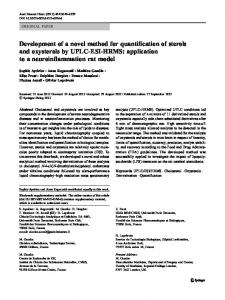
CIM
CIM to PIM mapping
PIM
PIM to PSM mapping
PSM
PSM to code mapping
Code Fig. 1. MDA Process
A. Models in the MDA The MDA separates certain key models of a system, and brings a consistent structure to these models [14]: Computation Independent Model (CIM): A computation independent model is a view of a system from the computation independent viewpoint. A CIM does not show details of the structure of systems. A CIM is sometimes called a domain model and a vocabulary that is familiar to practitioners of the domain in question is used in its specification. Platform Independent Model (PIM): A platform independent model is a view of a system from the platform independent viewpoint. A PIM exhibits a specified degree of platform independence so as to be suitable for use with a number of different platforms of similar type. Platform Specific Model (PSM): A platform specific model is a view of a system from the platform specific viewpoint. A PSM combines the specifications in the PIM with the details that specify how that system uses a particular type of platform. Fig. 1 demonstrates how these models will be created in an MDA development process. B. Model Standardization in the MDA OMG has adopted a number of technologies, which together enable the Model Driven Architecture. These include MOF, UML, CWM, XMI, and profiles (such as the profiles for EDOC, EJB …). Refer to [19] for more information. MOF (Meta Object Facility): MOF is an extensible model driven integration framework for defining,
CONSISTENT MODELING OF ZACHMAN FRAMEWORK CELLS
manipulating, and integrating metadata and data in a platform independent manner. MOF-based standards are in use for integrating tools, applications, and data. All MDA models are based on MOF. We discuss about this issue later in more details. UML (Unified Modeling Language): A specification defining a graphical language for visualizing, specifying, constructing, and documenting the artifacts of distributed object systems. The current official version for MDA is UML 2.0. Note that UML 1.x does not support all aspects of MDA. Refer to [16] for more information concerning UML 2.0. OCL (Object Constraint Language): The OCL is an addition to the UML specification which provides a way of expressing constraints and logics on models. CWM (Common Warehouse Meta-model): The CWM standardizes a complete and comprehensive meta-model that enables data mining across database boundaries at an enterprise and goes well beyond. It forms MDA mapping to database schemas. The CWM does for data modeling what UML does for application modeling. BPDM (Business Process Definition Meta-model): This Meta-model is developed for business processes. Such a meta-model is independent of specific process definition languages and would allow MOF-compliant models to interface with languages like WSBPEL and notations like BPMN. BSBR (Business Semantics for Business Rules): This meta-model is developed for capturing business rules in business terms, and the definitions and semantics of those terms in business vocabularies. In fact, there will be two specifications: a more generic standard for business rules, and a more specific one for production rules that are actually used by rule engines. To find more information about this meta-model refer to [15]. WSM (Web Services Meta-model): This meta-model is developed in order to facilitate the development of MOFcompliant web service models. UML Profiles: UML Profiles tailor the language to particular areas of computing (such as Enterprise Distributed Object Computing) or particular platforms (such as EJB, .Net, or CORBA). IV.
CONSISTENT MODELS FOR ZF
As mentioned earlier, one of the difficulties we are facing to use ZF is the problem of incoherent models. ZF expresses what information must be created for each cell of the framework; however, it doesn't indicate how this information must be created and which model(s) must be applied to present that information. In addition, there is not a set of coherent and consistent models across the entire cells. We are not intended to address these as ZF weak points, since ZF is just a framework, not a methodology. Anyhow, an architect who uses ZF has to overcome these problems. In this section, we investigate the use of MDA in Zachman Framework in order to suggest a practical model for each cell.
377
This can improve the usability of ZF for the developers who intend to put it in practice. A. The Problem Space We mentioned that ZF contains six rows, each representing one stakeholder perspective. The question is: "shall we propose a method for the entire rows?" We answer the question in this section. The first row of ZF specifies the architecture boundary. J.A. Zachman indicates that this row is a list of important things to the enterprise [11], and not a model. It seems that using natural language is the best way to describe this row. So, the first row does not exist in our problem space. Second till fifth rows model businesses, systems, technologies, and detailedrepresentations, respectively, and they exist in our problem space. The sixth row is not a model at all. It represents the actual deployed or running elements, data, and people of the organization. It is not a perspective, as such, but the "real world" in all its complexity. This row is usually omitted from ZF, and does not exist in our problem scope. B. Acceptability An accepted modeling approach shall be: • Integrable: We shall integrate all models together. • Wide covering: We shall apply an approach to model as more cells as possible. • Be standard: We shall not use strange and uncommon modeling elements, since they are not standard. • Easily understandable • Up-to-date C. The Proposed Method Fig. 2 depicts the initial scheme with respect to the mapping between the rows in ZF and different model types in MDA. In the primary plan, CIM is employed for the second row. As a result, all the models related to the cells of the second row (owner), to be proposed later; have to be described in the CIM level. In the third row, we use PIM, therefore all the models for the designer row cells have to be in PIM level. PSM is recommended for the fourth and fifth rows and all the cells constituting the builder and contractor rows will be designed in the PSM level. CWM is the best option for Data column modeling; however it should be noted that using simpler models is recommended for the higher rows in the framework. We use Zachman Framework
Data
Function
Network
People
Time
Motivation
Planner Owner Designer Builder Contractor Functioning Enterprise
CIM PIM PSM Code
Fig 2. Applying MDA models to Zachman Framework rows
OSTADZADEH ET AL.
378
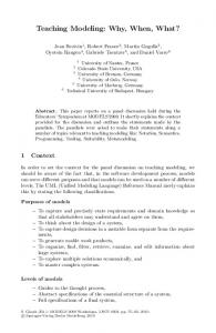
Business profile for the owner/data cell. Relations between data are also demonstrated using Specialization/ Generalization, Aggregation, and Inclusion relationships. In order to model the remaining rows we adopt CWM. Since the stakeholders of these rows are familiar with formal methods of software modeling, it is expected that no problem will occur using CWM. However, it should be noted that the CWM models for the third row have to be in the PIM level and for the fourth and fifth rows they should be in the PSM level. We prefer employing BPDM to model the Function column. As with the Data column, we try to use simpler models for the higher rows in the framework. We utilize Business Use Case diagram for the owner/function cell. Each process in the enterprise is modeled with a Use Case and organized with Aggregation and Inclusion relationships. Activity diagram is also used to present the workflow of processes. We utilize BPDM for the designer/function cell. Since builder/function cell is considered as design of applications, we employ UML 2.x diagrams to model this cell. Finally, for the contractor/function cell we refer to PSMspecific profiles. Considering chosen technologies, it's possible to use WSM and CORBA, EJB, and .Net profiles. The owner/network cell is modeled with the Organization Unit stereotype contained in UML Packages. Relations between organization sections are depicted using the Dependency relationships and their essences are clarified with extra comments. To model the designer/network cell, we employ the EDOC profile. It enables us to model different parts of organizational computations which are distributed within an enterprise. Deployment diagram is used for the builder/network cell. This gives us the opportunity to model hardware resources and their relations. We also utilize WSM and PSM-specific profiles (CORBA, EJB, and .Net) for the contractor/network cell. In order to model the People column in the second row, we employ the Use Case diagrams along with the Business profile. Organization structure is depicted with nested Packages and Organization Unit stereotype. Worker, Case Worker, Internal Worker, External Actor or Work Unit symbols are used for organizational roles. Communication diagram is also employed to show the workflow. We use BPMD for the designer/people cell. Interaction Overview Zachman Framework
diagram included in UML 2.x is utilized to model the builder/people cell. Unfortunately, modeling the contractor/people cell causes a problem since no particular diagram in MDA is suitable for defining the out-of-context characteristic of the workflow. However, utilizing the method proposed in the builder/people cell, and with the help of extra comments, it's possible to model this cell to some extent. Time column can be modeled with Timing diagram and Scheduling profile which are presented in UML 2.x. In the past, proposed solutions often utilized Sequence diagram to model this column [7], however it is not possible to correctly demonstrate the duration of an event with this diagram. Using the Timing diagram allows us to specify the exact start and end times and the duration for each event. In the third row, it is possible to employ the State diagram along with the Timing diagram to show different states. OCL is often recommended for the Motivation column modeling. However, it should be noted that using this language causes trouble in higher rows. The OCL language is a formal language to specify rules and constraints. Its thorough understanding requires familiarity with some concepts of formal specifications in mathematics. This requirement leaves it vague for the managements who are probably unfamiliar with formal concepts. Besides, OCL is designed for stating rules and constraints upon objects, nevertheless the abstraction level related to the higher rows of the framework is beyond the concept of an object and using objects to model these levels is inappropriate [20]. We use Business Motivation Model (BMM) diagrams related to BSBR, to model the owner/motivation cell. By defining goals, viewpoints, missions, objects, facts, strategies, and so on along with their relations, BMM diagrams try to model the concepts governing the processes within an enterprise. To model the builder/motivation cell, Production Representation Rule (PRR) is employed. This meta-model, let us specify the rules which are defined in the second row in the form of CIM as a presentation of production rules in PIM level. OCL is used to state the rules supervising current objects for the fourth and fifth rows. Fig. 3 summarizes our proposed method. All models can be integrated, since they are MOF-compliant. This characteristic guarantees that all models used in an MDA system can communicate with every other MOF-compliant model.
Data
Function
Time
Motivation
Owner
Business profile
Business Use Case
Organization Unit stereotype
Business profile/use case
Timing diagram
BSBR BMM
Designer
CWM
BPDM
EDOC
BPDM
Timing & State diagrams
PRR
Builder
CWM
UML 2.x
Deployment diagram
Interaction Overview diag.
Timing diagram
OCL
Contractor
CWM
CORBA, EJB, .Net, WSM
CORBA, EJB, .Net, WSM
Interaction Overview diag.
Timing diagram
OCL
Planner
Network
People
Out of problem space
Fig 3. Consistence models for Zachman Framework cells
CONSISTENT MODELING OF ZACHMAN FRAMEWORK CELLS V.
CASE STUDY
The solutions provided in the field of Software Engineering are less likely to be proved using formal methods. Instead, we usually analyze them through case studies. Certainly, a case study is an initial test in a sample environment and the actual performance of a method can only be evaluated after years of experiments in real world. Here are the steps we used in our case study: 1. Choosing an enterprise and checking its need for architecture. 2. Understanding the enterprise (architecture domain) 3. Modeling the first row of Zachman framework utilizing the information from the previous step. 4. Modeling the remaining rows in the Zachman framework using the proposed method. 5. Fixing weak points in the modeled cells. The enterprise that we chose for our case study is one of the Functional Architectures of FAVA project [3] in the I.R.I presidential office. FAVA architectures consist of two main parts: Fundamental Architectures and Functional Architectures. One of the Functional Architectures is the Trace/Action Functional Architecture on which this case study is based. FAVA project is designed using CHAM [5]. We do not intend to specify the details of CHAM, however it is worthwhile to mention that in CHAM, the architecture design is done in two phases: Macro Architecture design and Detailed Architecture design. In the macro architecture design phase we have specified the architecture essence. This phase for the Trace/Action Functional Architecture is presented in [6]. In the detailed architecture design phase we specify the architecture details and the implementation methods. In this phase we had to use one of the enterprise architecture frameworks, so we used Zachman framework based on our proposed method. You can find the detailed architecture design of the Trace/Action Functional Architecture in [6]. In this case study we planned to answer the following key questions: • Are all the cells modeled in one paradigm? • Are the Zachman framework cells created using simple models based on E/R relationship? • Is this architecture capable of utilizing different technologies? • Does the proposed modeling method satisfy the architect needs to express his/her ideas? VI.
THE PROPOSED METHOD vs. OTHER METHODS
We defined some characteristics in sections 4 (B) and 5. To compare the proposed approach with other approaches we evaluate these characteristics on five-scale criterion: (0) Null The approach does not have the characteristic at all. (1) Unknown - The status of the characteristic is unknown in the relevant approach. (2) Weak - The approach has the characteristic in an initial way. (3) Average - The approach has the characteristic. (4) Strong - The approach completely
379
supports the characteristic. Table 1 shows the result of this comparison. TABLE 1. The Proposed Approach Rank
Integrable Wide covering Being standard Easily understandable Being up-to-date One paradigm E/R Technology Idea expressibility VII.
[7] 3 2 3 4 3 4 4 0 1
[17] 2 4 3 3 3 0 4 3 2
[18] 2 2 0 3 3 3 4 2 1
Ours 4 3 4 2 4 4 4 4 3
CONCLUSIONS
In this paper a method for consistent modeling of Zachman framework cells was proposed. Compared to other frameworks, ZF has some evident advantages. These advantages have caused its extensive usage as the basic framework of enterprise architecture in the present time. However, an architect should face the lack of consistent and coherent models for its cells. In this paper, we proposed a novel method for modeling the ZF cells. The presented method adopts the latest standards of OMG modeling (MDA). We inspected the method in practice by employing it in a case study. The results were promising compared to previously proposed methods, indicating that it is well suited to diminish the modeling problems one is facing using the ZF, to a great extent. This research demonstrated how the models in ZF cells can be made coherent in order to avoid inconsistencies within the framework. In general, our method can increase the success rate of information system projects within enterprises. In our proposed solution, the forth and fifth rows of People column don't have well defined models. In future works, one is expected to suggest some MOF-compliant models for these cells. Considering the fact that those models are MOFcompliant, they can be integrated with our proposed solution, achieving full support of the Zachman Framework. REFERENCES [1] S. S. Ostadzadeh, A Unified Modeling Approach for Zachman Framework based on MDA, MSc thesis, Science & Research branch of Islamic Azad University, Tehran, 2006. [2] S. S. Ostadzadeh, "MDA role in Enterprise Architecture", Technical Report, Science & Research branch of Islamic Azad University, Tehran, 2005. [3] A. Majidi, "FAVA: Strategic Plan & Architecture", Technical Report, I.R.I Presidential Office, ITC, Tehran, 2004. [4] A. Majidi, "eGovernment: Strategic Plan & Architecture", Technical Report, Institute for Strategic Researches in Information Technology (IRIT), I.R.I Presidential Office, ITC, Tehran, 2005. [5] A. Majidi, "CHAM: National Framework & Methodology for Macro/Micro Systems", Technical Report, Institute for Strategic Researches in Information Technology (IRIT), I.R.I Presidential Office, ITC, Tehran, 2005.
380
OSTADZADEH ET AL.
[6] S. S. Ostadzadeh and A. Majidi, "Track/Action Functional Architecture", Technical Report, Institute for Strategic Researches in Information Technology (IRIT), I.R.I Presidential Office, ITC, Tehran, 2005. [7] A. Fatholahi, An Investigation into Applying UML to
Zachman Framework, MSc thesis, Shahid Beheshti University, Tehran, 2004. [8] D.S. Frankel, Model Driven Architecture: Applying MDA to Enterprise Computing, OMG Press, Wiley Publishing, 2003. [9] J.A. Zachman, The Zachman Framework: A Primer for Enterprise Engineering and Manufacturing, 2003. [10] J.A. Zachman, "A Framework for Information Systems Architecture", IBM Systems Journal, Vol. 26, No. 3, 1987. [11] J.A. Zachman, "The Framework for Enterprise Architecture – Cell Definitions", ZIFA, 2003. [12] G. Booch, B. Brown, S. Iyengar, J. Rumbaugh, and B. Selic, "An MDA Manifesto", MDA Journal, May 2004. [13] D. D'Souza, "Model-Driven Architecture and Integration", Kinetium, March 2002. [14] MDA Guide, OMG document, 2003. http://www.omg.org/ [15] S.J. Mellor, K. Scott, A. Uhl, and D. Weise, MDA Distilled: Principles of Model-Driven Architecture, Addison Wesley, 2004. [16] D. Pilone and N. Pitman, UML 2.0 in a Nutshell, O'Reilly, 2005. [17] System Architect Manuals, Building Enterprise Architecture: The Popkin Process, Popkin Company, 2004. [18] S. S. Ostadzadeh, "Development of Zachman Framework using the Rational Unified Process and the Unified Modeling Language", Technical Report, Science & Research branch of Islamic Azad University, Tehran, 2004. [19] Object Management Group Document, http://www.omg.org/technology/documents/ [20] F. Shams Aliee, Modeling the Behavior of Processes Using Collaborating Objects, PhD Thesis, University of Manchester, Manchester, May 1996.