A Method for Model Based Design of Rich Internet Application Interactive User Interfaces M. Linaje, Juan C. Preciado, and F. Sánchez-Figueroa Quercus Software Engineering. Universidad de Extremadura (10071 – Cáceres, Spain)
[email protected];
[email protected];
[email protected]
Abstract. During the last years, Web Models have demonstrated their utility facilitating the development of Web Applications. Nowadays, Web Applications have grown in functionality and new necessities have arisen. Rich Internet Applications (RIAs) have been recently proposed as the response to these necessities. However, present Web Models seem to be incomplete for modelling the new features appearing in RIAs (high interactivity, multimedia synchronization, etc). In this paper we propose a Model Driven Method, validated by implementation, called RUX-Model that gives support to multi-level interface specifications for multi-device RIAs. Keywords: Rich Internet Applications, Models, Web Engineering.
1 Introduction Web distribution architecture has inherited benefits such as low maintenance costs, decentralization and resource sharing among others. During the last few years, the growth of Web projects has brought about the development of models and techniques coming from the Web Engineering community. Nevertheless, the complexity of activities performed via Web interfaces keeps increasing, coming close to that of desktop applications. In this context, HTML-based Web Applications are showing their limits when considering high levels of interaction and multimedia support [5]. One solution to this limitation resides in Rich Internet Applications (RIAs) which combine the benefits of the Web distribution model with the interface interactivity of desktop applications. However, there is still a lack of complete development models and methodologies related to the new capacities offered by RIA [11]. As a result of RIAs technological characteristics and requirements, the current methodologies can not be directly applied to model and generate them. Most Web methodologies do not support multimedia properly, their focus being on data intensive Web applications (e.g., WebML [3], UWE [7] and OO-H [6]). In addition, most of the multimedia methodologies are not data intensive oriented and they focus on temporal specifications to support multimedia/animations and final-user interaction (e.g., HMT [2] and OMMMA [4]). According to previous studies, these methodologies do not cover RIA composition parameters fully at all [11]. To be more precise, Web modelling approaches can be extended towards RIA modelling in two different directions: 1) sharing business logic and establishing data L. Baresi, P. Fraternali, and G.-J. Houben (Eds.): ICWE 2007, LNCS 4607, pp. 226 – 241, 2007. © Springer-Verlag Berlin Heidelberg 2007
A Method for Model Based Design of RIA Interactive User Interfaces
227
persistence between client and server sides; 2) extending Web User Interface (UI) capacities to specify the richness of presentation and interaction in RIA. The first issue is beyond the scope of this paper and has been treated in [5]. For the second issue, lessons learned from Multimedia and Hypermedia fields are necessary. The contribution of this paper is a Model Driven Method for the definition of rich UIs with high levels of user interaction and multimedia temporal relationships called RUXModel (Rich User eXperience Model). This proposal is validated by implementation on RUX-Tool (the RUX-Model CASE Tool available at http://www.ruxproject.org/). The rest of the paper is organized as follows: in section 2 the main design decisions for RUX-Model are shown and argued, after which in section 3 we describe RUXModel in detail. Finally, conclusions and future work are outlined in section 4.
2 Design Decisions in RUX-Model Due to RUX-Model being a multidisciplinary proposal and in order to decrease crosscutting concepts, the interface definition is divided into levels. According to [14] an interface can be broken down into four levels, Concepts and Tasks (which has no bearing in RUX-Model, it correspond to the hypertext model level and is the starting point for RUX-Model), Abstract Interface, Concrete Interface and Final Interface. In RUX-Model each Interface level is composed by Interface Components. For the Abstract Interface we are interested in models as independent as possible. RUX-Model Abstract Interface is partially based on Object-oriented Modelling of Multimedia Applications (OMMMA) [4] in order to define the set of media components. OMMMA is independent enough, but quite limited, so it must be improved by adding RUX-Model views and connector elements. The Concrete Interface in RUX-Model consists of spatial, temporal and interaction UI presentations. Spatial Presentation.- There are many proposals to build a generic interface common to multiple devices and to customize it for specific devices [12]. Among them, our interest is focused on those languages being scalable and flexible enough to be extended with new features and, if possible, being standard. We have selected User Interface Modelling Language (UiML) [1]. UiML might be the most well-known and widely spread general XML-based UI description language. However, UiML is not enough to deal with some RIA necessities [10], so several extensions to UiML are proposed in RUX-Model. Temporal Presentation.- The main interest is on the definition of temporal logic relations among Interface Components and the validation of the set of temporal relations allowed. In this sense, the Synchronized Multimedia Integration Language (SMIL) [15] is used to express temporal logic relations. Graphical commonly-adopted representation of SMIL is based on Petri Nets. RUX-Model uses Petri nets’ structure as a bipartite directed multigraph. Timed Petri Nets (TOCPNs) are introduced for multimedia presentations in [8] and extended in DMPS [9], but they have mainly been used to give temporal functionality to static multimedia presentations of desktop systems. So, in RUX-Model graphical representation of Temporal Presentation definition is lightly inspired by sequence diagrams defined in OMMMA. The set of possible temporal relations in RUX-Model has been validated by correspondences of the set of temporal relations defined in HMT [2].
228
M. Linaje, J.C. Preciado, and F. Sánchez-Figueroa
Interaction Presentation.- The proposal that covers part of our goal is XML Events [16]. The XML Events is an events syntax for XML that provides XML-based languages with the ability to uniformly integrate event listeners and associated event handlers with Document Object Model event interfaces. Handlers in RUX-Model are attached to the Temporal or Interaction Presentations. An event handler in RIA must be able to define the alterations of the presentation caused by the user interaction and the connections with the underlying business logic. UiML has a nice proposal to define handlers but it is not powerful enough to express RIA capabilities according to [10], so RUX-Model extends it and proposes a graphical representation over it to specify handlers in a visual way based on Flow Charts. In addition, OCL is used when low level detail operations are to be performed. RUX-Model Final Interface describes the final UI according to RIA selected rendering technology. At the moment, the technologies considered in RUX-Model are Flex [17], Lazslo [18], and Ajax together with DHTML, but the model should be able to describe similar RIA rendering technologies (e.g., XUL or XAML). Table 1. Summary of RUX-Model related technologies and their extensions Concrete Interface Abstract Interface
Final Interface Spatial
Temporal
Interaction
Extended to represent graphically condition-action trees
Flow Charts
-
-
HMT
-
-
To validate the set of temporal relations
-
-
OMMMA
Extended to define and group Media
-
Extended to perform sequence diagrams
-
-
TOCPN DMPS
-
-
To express Temporal Logic Relations
-
-
OCL
-
-
SMIL
-
-
UiML
-
Subset for Structure and Style of the UI
XICL
Extended to define Interface Components
XML Events
-
AJAX,FLEX,LASZLO
Very low level specification of handlers To express temporal logic relations
-
Extended to specify handlers
Extended to define and map Interface Components -
-
Listener definitions
Used to define the set of Concrete Interface Components
-
Extended to define and map Interface Components Rich Render Technology
Finally, glue between levels is needed. XICL (eXtensible user Interface Components Language) [13] is an extensible XML-based mark-up language for the development of UI components in Web systems and browser-based software applications. XICL allows not only the specification of components with their properties, methods and so on, but also the definition of target platforms and the mapping among Interface Components. RUX-Model extends XICL to define Interface Components and to establish mapping options between two components of adjacent Interfaces.
A Method for Model Based Design of RIA Interactive User Interfaces
229
Due to the amount of RUX-Model related technologies, table 1 summarizes the models, methodologies and languages selected to be used or extended in order to conform parts of RUX-Model. We must clarify that RUX-Model does not depend on any of these models and languages and just takes advantage of these previous works.
3 RUX-Model Core RUX-Model is an intuitive visual method that allows designing rich UIs for RIAs. Main RUX-Model features are: • • • •
It defines reusable interfaces: RUX-Model Abstract Interface is reusable because it is common to all the RIA platforms, so all the devices that can run this kind of application may use the same Abstract Interface. It allows the spatial arrangement of the UI to be specified, as well as the look&feel of the interface elements based on a flexible set of RIA components. It models the temporal aspects, allowing the specification of those behaviours which require a temporal synchronization. It allows the user’s interactions with the RIA UI to be modelled based on the active Interface Components definition.
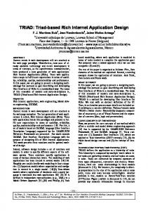
RUX-Model allows communication with the underlying hypertext application, hence data-content and functionality is offered by the HTML-based Web application. The final application’s functionality is thus dependent on the chosen Web model capacities. Thus, RUX-Model is formed by the definition of a set of interfaces with distinctive responsibilities and abstraction levels (Figure 1).
Fig. 1. RUX-Model MDA overview
The development process in RUX-Model has four main stages: connection with the previously defined hypertext model, definition of the Abstract Interface, definition of the Concrete Interface and the specification of the Final Interface, which ends in code generation. In RUX-Model each stage is fed by the previous one, as well as by the Component Library and the mapping possibilities specified in XICL (Figure 1). The first stage in RUX-Model deals with the connection with the previous hypertext model (e.g., WebML, OO-H or UWE). At this stage, the presentation elements
230
M. Linaje, J.C. Preciado, and F. Sánchez-Figueroa
and the relationships among them are extracted, as well as the defined operations on the Web model. The Connection Rules ensure RUX-Model to adapt to the system requirements shaped in the previous Web model. On the basis of the results offered by the Connection Rules, RUX-Model builds the Abstract Interface, by means of which we can specify an interface which is independent from the platform and the final display device. From the Abstract Interface, through the application of the first set of Transformation Rules, the Concrete Interface, which allows the appearance, spatial arrangement, temporal and interactive behaviour, is obtained. Finally, from the Concrete Interface and through the second set of Transformation Rules, we obtain the Final Interface, which has inherited, among others, the connection with the previous Web model. Model Driven Architecture (MDA) is an approach to software development that provides a set of guidelines for structuring specifications expressed as models. Using the MDA methodology, system functionality may first be defined as a Platform Independent Model (PIM) through an appropriate Domain Specific Language. PIM may then be translated to one or more Platform Specific Models (PSMs) by mean of a set of Transformation Rules. According to MDA approach, the relationship among each one of the stages of RUX-Model goes as follows (Figure 1): For each hypertext model you get an Abstract Interface (PIM). For each Abstract Interface you get n Concrete Interfaces (PIM). For each Concrete Interface you get m Final Interfaces (PSM). Thus, by using RUX-Model it is only necessary to specify a common Abstract Interface for the different Concrete Interfaces. Hence, every Concrete Interface can be specified in order to be rendered in one or more specific platforms. The application building process finishes with a stage in which the transformation engine generates the code dependent on the chosen target specific platform. 3.1 Connection Rules By defining a certain set of rules, called Connection Rules, we ensure the RUXModel connection integrity with the previous Web model. The set of Connection Rules establishes the way the matching takes place among the elements in the previous Web model and the Abstract Interface. RUX-Model extracts (from the Web model it connects) the structure and navigation in order to use them to create an initial Abstract Interface model, and to grant the Concrete Interface model access to the “operation chains” or “operation points”, which represent the operational links in the hypertext navigation models. The process starts when we choose the set of Connection Rules to be used, which are defined specifically regarding the previous Web model taken. The following is extracted from the previous Web model: • The data used by the Web application and its relationships. • The existing hypertext element groupings. • The connections between pages, which allow us to put the application in context.
A Method for Model Based Design of RIA Interactive User Interfaces
231
3.2 Transformation Rules and the Component Library Following MDA, we will focus on defining models and specifying Transformation Rules in order to systematize the RIAs construction process. In order to understand the way the Transformation Rules are applied in the steps PIM2PIM and PIM2PSM (Figure 1), we need to know the specifications for the Interface Components involved in each of the RUX-Model Interface levels. In RUXModel an Interface Component is defined by its name, its identifier (required) and a set of properties, methods and events, which are optional. Thus, RUX-Model is made up among others of Abstract Interface Components, Concrete Interface Components and Final Interface Components. With the aim of making the access and the maintenance of the Interface Components easy, RUX-Model specifies a Component Library, which is responsible for: 1) storing the components specification (name, properties, methods and events) 2) specifying the transformation capabilities for each component from an Interface level in other components in the following Interface level and 3) keeping the hierarchy among components at each Interface level independently to every other level.
Fig. 2. Component Library E-R description
The Component Library specified in Figure 2 maintains the specifications of the Interface Components and their relationships along the modelling process. The set of Interface Components defined in the library can be increased or adapted by the modeller to its needs and according to the specifications of the project. Properties, methods and events of each Component can be extended at any time. The transformation specifications contained in the Component Library are added to our own XICL extended specification (see http://ruxproject.org/xiclext.pdf for further information) in order to declaratively specify which are the transformation options available to be carried out on each Interface Component. XICL extensions allow RUX-Model to keep the definition of several target platforms in a single XML document, as well as the translation of an origin component to one or more target platforms when we specify PIM2PSM Transformation Rules. This is a basic capability of the RUX-Model Transformation Rules not existing in XICL that was designed primarily to create HTML components. XICL mixes spatial
232
M. Linaje, J.C. Preciado, and F. Sánchez-Figueroa
arrangement and interaction, which is not a desirable feature in our model. XICL original component tag has been extended to allow several platforms and reference each component to the platform it belongs to. Also the properties declaration has been modified and unused elements and attributes have been removed. Moreover, a strict key reference definition has been added to XICL to facilitate checking the Transformation Rules. Abstract to Concrete Interface (PIM2PIM): PIM2PIM Transformation Rules establish the correspondences which are allowed among Abstract Interface Components and among Concrete Interface Components. The set of different components which can form the Abstract Interface is fixed and limited by a number of elements set by RUX-Model as native (mentioned later), even though it is conceptually extendable extending the Component Library. The size of Concrete Interface Components set is variable and depends on the number of RIA elements to be defined dynamically in the Component Library. Applying these rules on the Abstract Interface allows creating a first version of the Concrete Interface. Concrete to Final Interface (PIM2PSM): This case is different from PIM2PIM in the fact that now both the set of origin components (Concrete Interface) and the set of target components (Final Interface) are changeable and dynamic within the Component Library. In the Component Library, the Concrete Interface Components are defined and we detail a series of final platforms. The methods, events and properties mapping is done individually by each component and target platform that we want to deploy in the Final Interface level. For instance: we define our native Concrete Interface Component called tabnav, which could become the TabNavigator FLEX component or the tabpane Laszlo component. 3.3 Abstract Interface Abstract Interface lets us obtain an abstraction on the chosen Web model, obtaining a common representation for the hypertext systems currently used in the Web. This Interface can be initially obtained from the selected Web model by using the Connection Rules. A refinement process is allowed, in which the modeller can add and/or restructure the Abstract Interface if it is considered necessary until the modeller’s goal is achieved.
Fig. 3. RUX-Model Abstract Interface formal description
A Method for Model Based Design of RIA Interactive User Interfaces
233
RUX-Model Abstract Interface is composed by connectors, media and views. Figure 3 shows the Abstract Interface elements and the relations among them. 1) Connectors. They are related to the data model once it is specified how they are going to be recovered in the hypertext model. Web development methodologies typically give the hypertext model some characteristics which allow, for instance, specifying the way a set of registers recovered from a database is going to be ordered and so on. Each connector owns an attribute called “sourceid” among others which identifies its connection with the underlying Web model. 2) Media. They represent an atomic information element that is independent of the client rendering technology. The availability of media components and their grouping is based on OMMMA. In RUX-Model they are categorized into discrete media (texts and images) and continuous media (videos, audios and animations). Each media gives support to Input/Output processes, so it is possible to design multimodal RIAs’ UIs. This is necessary since RIA allows audio/video inputs over the Web. Common media attributes are “source” and “connectorid”. These attributes are used to define dynamic data source of the media (from the underlying Web model). 3) Views. In the Abstract Interface, a view symbolizes a group of information that will be shown to the client at the same time. In order to group information, RUX-Model allows the use of four different types of containers: simple, alternative, replicate and hierarchical views. In RUX-Model, the root element of the Abstract Interface is always represented by a view. 3.4 Concrete Interface The Concrete Interface specifies the presentation and behaviour of the UI that has to be modelled, depending on how we want the application to be. The UI of the Concrete Interface deals with a UI common to all the current RIA final rendering technologies and it is formed by three additional “presentations” in order to minimize crosscutting: Spatial, Temporal and Interaction Presentations. In order to offer the modeller intuitive visual models for the different presentations, RUX-Model provides each one of them with their own intuitive graphic representation that is backed by modelling languages or representations based on standards. 3.4.1 Spatial Presentation The Spatial Presentation in RUX-Model is responsible for specifying over the Abstract Interface the positioning, dimension and look&feel of the Interface Components in the application space. RUX-Model gives the modeller a set of native RIA components (see http:// ruxproject.org/nativecomp.pdf for further information) which have been defined on the basis of a component set which is currently present in nearly all current RIA rendering platforms. The choice of these components is the fusion among the groups of components in the platforms Laszlo, Macromedia Flex, Macromedia Flash and XUL that are well-known RIA development platforms. RUX-Model Concrete Interface Components can be classified in three categories: Controls (components used to gather the user entries or to provide the user with output information), Layouts
234
M. Linaje, J.C. Preciado, and F. Sánchez-Figueroa
(components able to distribute and/or gather the elements in the Concrete Interface) and Navigators (components able to provide navigation among the stack layout and other typical navigation components). As we have mentioned before, the Component Library is responsible among other things for keeping the Interface components specification, both the native Concrete Interface ones and those new ones that modellers want to add. The RIA native set of components has been specified in RUX-Model only to ease the modeller’s work. Additionally there are descriptions in two declarative languages: the first one, the XICL extension proposed which has already been commented on, and the second one, the usage of dynamic schemes extracted from the Component Library to maintain the hierarchical consistency among the components that compose the spatial presentation. The spatial presentation specification is simple from the point of view of the modeller, given that the grouping is given first by the Abstract Interface, so the modeller just has to refine the grouping, place the components spatially, and define their dimensions and look&feel. The textual specification of the RUX-Model spatial presentation RUX-Model uses a subset of the specification proposed by UiML, which is formed by part of the children defined in UiML inside the node . This includes the nodes and , avoiding the use of and nodes. 3.4.2 Temporal Presentation The goal of the RUX-Model Temporal Presentation is to represent those behaviour which take place without the direct mediation of the user and establish a series of temporal relationships between the different Interface Components in the presentation. It is very useful in order to represent behaviours that take place in a temporal way on the Concrete Interface Components or to specify calls to the underlying business logic in a predefined way based on time events. The Temporal Presentation is defined on the Spatial Presentation in order to be able to specify how changes affecting the RIA UI will take place. The temporal presentation is made up of the temporal presentation elements, which are Concrete Interface Components or groups of Concrete Interface Components, whose spatial presentation is already defined. It is possible to establish the temporal relationships logic between the elements (E) of the temporal presentation and also group temporal presentation element (G) which can contain one or more temporal elements in order to share a temporal logic. In this sense, to illustrate better the implied processes in temporal relationship logic, we define some concepts implied in this logic. Real Using Time: linearly elapsed time from when the application starts running in the client until the client finishes the application. Predefined Using Time: time used to specify the duration of a temporal behaviour established on one or more temporal presentation elements. The Real Using Time will always be equal to or higher than the Predefined Using Time, given that it is possible for a user to pause, play and restart the temporal behaviour in a temporal presentation element.
A Method for Model Based Design of RIA Interactive User Interfaces
235
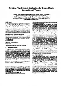
Moment: We can at any time “take a picture” of the temporal state of the components in the presentation, defining a precise moment of the Real Using Time. Every moment is defined according to the temporary situation at a given instant of all the temporal presentation elements. Temporal Presentation definition takes place through triads of the kind E[E’:V0, E’’:VF, {handler:VE}] and is graphically represented by an extended sequence diagram that expresses how the elements behave in time and how these behaviours affect other elements. In this triad the values are referred to as follows: E: Temporal Presentation element target of the indicated temporal logic. E’: Temporal Presentation element with which E is related in order to start its temporal behaviour in a synchronized way. V0: Delay in the start of element E regarding the start of element E’. It can contain a real value. E’’: Element with which E is related to finish its temporal behaviour in a synchronized way. E’ and E’’ can refer or not to the same presentation element. VF: Delay in the end of element E regarding the end of element E’’. It can contain: END: Indicates that it ends when Real Using Time finishes. Real Value: Indicates the time units the temporal presentation element must last. Handler: Reference name for a handler in a set of defined handlers in RUX-Model. VE: Delay when launching the handler from the beginning of element E. It can contain a real value. Related to the couple handler:VE : 1) it can be repeated by modifying one or both values as many times as necessary, in order to indicate the launching of different handlers at different moments in the timeline E is acting in. 2) taking into account that the couple is compulsorily tied to a predefined temporal event E and gets affected by its temporal definition, the launching of the handler is also affected by such situation in a way that, if E is repeated in time, the launching of the handler will be too.
(a)
(b)
Fig. 4. Temporal Presentation description examples
The graphic representation of the temporal relationships logic is depicted in Figure 4a, where the element E1 starts just when the application begins to run and ends when the
236
M. Linaje, J.C. Preciado, and F. Sánchez-Figueroa
application finishes (here Real and Predefined Using Time are equal). Predefined Using Time of element E2 starts when E1 starts plus a three delay time units from E1 and ends four time units later. E3 is implicitly executed simultaneously to E2 for four time units and finishes at the same time as the Predefined Temporal Time of E1. In RUX-Model temporal representation diagram, the temporal presentation elements are placed on the left, while the temporal relationships logic that affects those elements is placed on the right. For each temporal presentation element in the diagram there is a temporal sequence that starts and finishes in a black dot. In case it being interesting to focus attention on just a part of the temporal diagram and there are other elements in the segment starting or finishing outside the shown range, this is shown by means of a white circle. This means that the element or group starts before or finishes after, depending on the situation, the shown Predefined Using Time range. Each handler launched by the temporal behaviour is symbolized in the diagram by a triangle. The definition of temporal representation on presentation element groups is done by quartets of the kind G[E’:V0, M, E’’:VF, {elements}]. These quartets are graphically represented in the extended sequence diagram and express the behaviour of elements in time and how these behaviours affect other elements or groups of elements. In the indicated quartet the values are referred to as follows: G: Group of temporal elements, target of the indicated temporal logic. E’: Temporal presentation element related with G to initiate its temporal behaviour in a synchronized way. V0: The initial delay of element G with respect to the start of element E’, it can contain a real value. M: Execution mode, which can be PAR, parallel (default value), or SEQ, sequential. Like SMIL, RUX-Model defines mainly two kinds of grouping: Parallel (PAR - plays child elements in parallel) and Sequential (SEQ - plays child elements in sequence). E’’: Element related with G to finish a temporal behaviour in a synchronized way. VF: Delay in the end of G regarding the end of element E’’, which can contain the following value: LOOP(n): Indicates that the group temporal logic will be repeated n times. n can also take the value END, thus indicating that it will be repeated until the application stops running. In Figure 4b an example of grouping is depicted where E9 begins running in the moment three of the Predefined Using Time and finishes seven time units later. E9 also triggers two handlers in the instant two from E9 runs. This temporal diagram also specifies that G1 begins running when E9 begins and defines a temporal sequence relation between E1 and E2, looping until the end of Real Using Time. The temporal relationships logic specifies the temporal behaviour of the Concrete Interface Components. For the attributes of a presentation element implied in a temporal behaviour the values wanted for the initial moment and those for the temporal elements in the final moment of the behaviour must be indicated. It is possible to associate values for the attributes of a presentation element related to the values of the attributes that other temporal presentation elements have in any moment.
A Method for Model Based Design of RIA Interactive User Interfaces
237
3.4.3 Interaction Presentation The objective of the Interaction Presentation in RUX-Model is to capture and represent those behaviours triggered by the user interaction. As in previously shown RUXModel phases, we have provided an intuitive graphic notation and a strong definition language at this point. In RIAs, capturing the user interaction with the UI is generally carried out by the application components that are able to capture certain event types. In RUX-Model, an event is the representation of some asynchronous occurrence (such as a mouse click on the presentation of the element) that gets associated with a Concrete Interface Component. An action is some way of responding to an event; a handler is some specification for such an action; a listener is a binding of such a handler to an event targeting some component. As the event capture definition language, RUX-Model uses XML Events, W3C Standard language for the event capture specification. The XML Events module provides RUX-Model with the ability to uniformly integrate event listeners and event handlers. XML Events is not limited to expressing conditions such as “if windows1 moves launch action1”. XML Events ease richness in expression in DOM based languages, which allows the event definition to affect all the children of the window (e.g., all the components previously defined in RUX-Model within a windowlayout, such as buttoncontrols, could get affected by a “drag” type event assigned to the father). In RUX-Model all events are declared globally in order to take advantage of the way events propagate. XML Events is based on the definition of “listeners” that are used to declare event listeners and register them with specific nodes in the DOM. It has several attributes: 1) event: the event type for which the listener is being registered; 2) observer: the id of the element with which the event listener is to be registered; 3) target: the id of the target element of the event; 4) handler: the URI of a resource that defines the action that should be performed; 5) phase: when the listener will be activated by the desired event (capture or bubbling phase); 6) propagate: whether after processing all listeners at the current node, the event is allowed to continue on its path (continue or stop); 7) defaultAction: whether after processing all listeners for the event, the default action for the event (if any) should be performed or not (perform or cancel); 8) id: event identifier. It’s important to note that XML Events does not specify available event types or actions. This feature is really important in RUX-Model, since event types are declared in the dynamic Component Library. The graphic notation of a listener is quite simple and it is related with the spatial presentation since events are registered over Concrete Interface Components. Over the spatial presentation, it a shape is depicted that contains the handler name and the event selected. In order to represent the relationship between the observer and the handler a line is also drawn to connect them. 3.4.4 Handlers Once the way the events are captured, defined and integrated with the handlers is specified, this section focuses on handler specification. Handlers in RUX-Model follow an Event-Condition-Action (ECA) model. Each ECA is defined by the Event (in RUX-Model defined in the listener declaration) and a
238
M. Linaje, J.C. Preciado, and F. Sánchez-Figueroa
Condition-Action-Tree (CAT) defined in the handler. With ECA, RUX-Model is able to define rules with actions that are triggered when some conditions are met. This behaviour model is more than enough to express both changes in the UI and calls on the business logic expressed in the defined Web Model. In RUX-Model, handlers are textually represented in a declarative way. The specification is based on a subset of UiML “behaviour” module that is composed of the following basic elements: 1) behaviour: the behaviour root element; 2) rule: this element defines a binding between conditions and actions; 3) condition: element that contains a logical expression based on the element. may also contain hierarchical op elements to compose more complex conditions. UiML available logical conditions are ==, !=, >,