Perforated squeezed-film damper structures are used ... Figure 1: Structure of perforated gas damper. ... are simulated with the time-harmonic PPR solver [12].
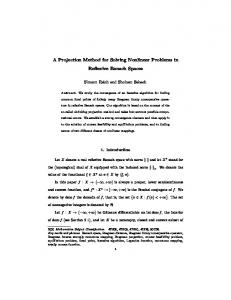
A Method for Solving Arbitrary MEMS Perforation Problems with Rare Gas Effects T. Veijola* and P. R˚ aback** * Helsinki University of Technology P.O.Box 3000, FIN-02015 HUT, Finland, timo.veijola@hut.fi ** CSC – Scientific Computing, P.O. Box 405, FIN-02101 Espoo, Finland. ABSTRACT We present a straightforward and fast method solving perforation problems utilizing a Perforation Profile Reynolds (PPR) solver. The solver includes additional terms in the modified Reynolds equation that model the leakage flow through the perforations, and variable viscosity and compressibility profiles. The solution method consists of two phases: 1) specification of the specific admittance profile and relative diffusivity (and relative compressibility) profiles due the perforation, and 2) solution of the PPR equation with a FEM solver. Damper strucures with 4 – 64 holes are simulated with a 3D Navier-Stokes solver and PPR solver. The results agree to within 15 % for perforation ratios less than about 50 %. The method extends the regime of accurate simulation of perforated structures for cases where the homogenization method is inaccurate and the full 3D Navier-Stokes simulation is too complicated. Keywords: damping, perforation, gas damper, rare gas, Reynolds equation
1
INTRODUCTION
Perforated squeezed-film damper structures are used in several MEMS applications, both, to reduce the damping due to the surrounding gas and to make the damping insensitive to the air gap height. In these structures, the number of perforations vary from a few holes to grids of thousands of holes. Accurate modeling of these structures requires the consideration of rare gas flow in tiny flow channels and around the structure. 3D flow simulations are needed in solving perforation problems generally. However, accurate 3D simulation of the Navier-Stokes (NS) equation is, in practice, impossible due to the huge number of elements needed, especially in cases where the number of perforations is relatively large. Moreover, the NS equations are incapable of modeling rare gas phenomena, that is essential when the gas is flowing in narrow flow channels, that are typical in MEMS devices. To model the damping in perforated structures, different methods should be used depending on the number of perforations and the nominal hole size s relative to the air gap height h (s/h-ratio). If the s/h-ratio is
large, the flow resistance of the perforation is insignificant. In this case, the problem can be reduced to a 2D Reynolds equation for the whole damper surface [1] (a few holes), or for a single hole (large number of holes) [2]. If the number of perforations is large, the flow resistance of the perforations is solved and is homogenized over the damper surface. The problem is reduced to the extended Reynolds equation with a pressure leakage term [3]–[7]. The homogenization method [7] is usable, but it has its limitations, especially if the number of perforations is small. A mixed-level approach has also been published [8], and a hybrid method combining NS and Reynolds equations has been presented [9]. Flow resistances of perforations are studied in [10]. In this paper, a method for solving damping problems is presented, where the homogenization method does not apply. These are, e.g., a moderate number of perforations, complex shaped perforations, and nonuniform distribution and size of perforations. Moreover, in the method, the border effects are considered.
2
METHOD
Figure 1 shows the structure of a perforated gas damper. The method makes use of the solver for the Perforav y
u
z x
h u
Figure 1: Structure of perforated gas damper. tion Profile Reynolds (PPR) equation (written in timeharmonic form): � � h3 Qch jωhp ∇p − Ch − Yh p = w, (1) ∇ · Dh 12η PA where h is the air gap height, η is the viscosity coefficient, Qch is the relative flow rate, PA is the ambient pressure, p(x, y, ω) is the complex pressure variation, and w is the surface velocity in the z-direction.
NSTI-Nanotech 2005, www.nsti.org, ISBN 0-9767985-2-2 Vol. 3, 2005
561
Dh (x, y), Ch (x, y), and Yh (x, y) are the extensions that are specific for perforated structures: relative diffusivity, relative compressibility, and perforation admittance profiles, respectively. The relative flow rate due to the rare gas effects is 1.159 , Qch = 1 + 9.638Kn,ch
(2)
and Kn,ch = λ/h is the Knudsen number, where λ is the mean free path (depends on PA ). When the slip correction is considered, as in this paper, Qch = 1 + 6Kn,ch.
2.1
(3)
2.2
Phase 2: PPR Solver
The PPR solver is implemented in the multiphysical simulation software Elmer [12]. The PPR equation is solved applying the local perforation admittance and relative diffusivity and compressibility profiles. Considering the edge effects at the outer borders of the structure is essential for accurate results. All borders of the structure are extended by an amount of 1.3d(1 + 3.3Kn,ch), as suggested in [13]. The borders of the perforations are not modified in this method. This is not needed, since the finite diffusivity at the perforations effectively builds an “edge effect”.
3
VERIFICATION
Several perforated dampers in perpendicular motion are simulated with the time-harmonic PPR solver [12] using a mesh of 5000 elements. The surface is a square, and the perforation consists of identical square holes.
562
0 Dh
Phase 1: Perforation Profiles
This method requires that the specific admittance profile of the perforated surface is built first. In PPR, the specific admittance profile Yh (x, y) is specified spatially, at the locations of the perforations, whereas in the homogenization method Yh is a constant and includes the flow resistance of the air gap and the perforations. In this paper, a constant average admittance profile is used for each perforation. The diffusivity of the air gap also effectively changes due to the perforation. For the flow passing in the air gap below the perforation, the frictional surface area will be reduced approximately by 2. This is modeled by setting the relative diffusivity Dh = 2 at the perforation (Dh = 1 elsewhere). Figure 2 illustrates the perforation profiles in the case of a 1D damper. For simple perforation geometries, e.g., rectangular or circular holes, analytic flow channel impedances with rare gas effects can be used to determine the flow impedance profile [11]. Complicated perforation shapes require a 3D FEM simulation to determine the specific admittance of each perforation.
a)
Yh
Ch
2 1 0 1 0
b)
Figure 2: a) Topology of a single perforation in 2D and b) reduced profiles in 1D for Eq. (1). A comparison is made well below the cutoff frequency, that is, the compressibility of the gas is ignored. The dimensions are summarized in Table 1 and one of the four structures is shown in Fig. 3. Number of holes N Surface length a Hole diameter s Thickness hc Air gap height h Viscosity coeff. η Mean free path λ
4, 16, 36, 64 10, 20, 30, 40 0.5, 1.0, . . . , 4.5 0.5, 1, 2 1, 2 20 69
10−6 m 10−6 m 10−6 m 10−6 m 10−6 Ns/m2 10−9 m
Table 1: Parameters for the simulated dampers. Altogether, 216 different topologies were generated and simulated. For a rectangular capillary, the average specific admittance at the opening of the hole is � �−1 hc wh s2 3π s = + , (4) Yh = ph 28.51η Qtb 16 where s is the diameter of the hole, hc is the length of the hole, and ph and wh are the average gas pressure and velocity in the z-direction at the opening of the perforation hole. In the slip flow region, the relative flow rate of a channel with circular cross-section Qtb is Qtb = 1 + 4Kn,tb,
(5)
where Kn,tb is the Knudsen number of the capillary
NSTI-Nanotech 2005, www.nsti.org, ISBN 0-9767985-2-2 Vol. 3, 2005
6h
s a 2s
hc
h
Figure 3: Structure of simulated dampers. Topology with N = 16 holes is shown. The figure also illustrates the simulation space around the structure in 3D NSsimulations. Kn,tb = λ/(s/2). In Eq. (4), an elongation of an open capillary (3π/16 · s) is used. The results are compared against full 3D NS simulations of the structure, which can be performed relatively reliably, thanks to the small number of holes and the symmetry in the structure. Slip boundary conditions are used for the surfaces. The simulated gas volume is extended around the damper: free space around and above the damper are 6h and 2s, respectively. A mesh of 250000 elements is used. Damping coefficients for varying hole sizes are calculated with both methods. The maximum relative errors are shown in Table 3. In Fig. 4, the simulated pressure profiles are compared.
4
DISCUSSION
The maximum relative error in the damping force is below 15%, except for very strong perforation (81 %) and long channels (hc = 2 µm) when N = 4. The PPR model systematically underestimates the damping. This is probably due to the fact that additional forces acting on the sidewalls and on the top surface are ignored in the model. These forces are stronger when the surface is thick (hc = 2 µm), and the surface area is the smallest (N = 4). The increase in the error at very strong perforation is probably due to the constant specific admittance profile. Also, the coupling of the flows above the perforations is not accounted for in this model, and the channel elongation exaggerates the damping. The number of elements (250000) in the 3D NS simulations was close to the maximum achieved in the com-
Max. relative error [%]
hc µm
s µm
r %
N =4
N = 16
N = 36
N = 64
0.5-1 0.5-1 0.5-1 0.5-1 0.5-1 0.5-1 0.5-1 0.5-1 0.5-1
0.5 1.0 1.5 2.0 2.5 3.0 3.5 4.0 4.5
1 4 9 16 25 36 49 64 81
-13.4 -8.6 -13.4 -14.1 -13.8 -16.3 -18.6 -17.8 -17.6
-2.3 -4.2 -5.4 -6.7 -9.6 -11.8 -12.6 -6.5 9.5
-1.3 -5.0 -6.0 -8.2 -11.0 -13.8 -12.6 -10.5 23.8
-1.7 -5.5 -9.1 -9.5 -13.0 -13.5 -13.1 10.9 28.8
2 2 2 2 2 2 2 2 2
0.5 1.0 1.5 2.0 2.5 3.0 3.5 4.0 4.5
1 4 9 16 25 36 49 64 81
-13.3 -15.4 -15.1 -19.9 -19.2 -22.3 -21.4 -25.4 -26.0
-3.7 -4.5 -6.2 -6.8 -7.5 -8.0 -8.3 -10.0 -0.9
-1.4 -3.8 -4.8 -5.6 -7.5 -9.0 -8.8 -5.4 8.0
-1.2 -2.9 -4.0 -5.8 -7.7 -9.5 -9.1 6.5 13.8
Table 2: Maximum relative errors of the PPR method compared with the 3D simulation with the NS solver. r = N s2 /a2 is the perforation ratio. puter used (1 GHz Compaq AlphaServer). Simulating each (of 216) topology took about half an hour. The absolute accuracy of the numerical results is questionable since no proper grid convergence analysis could be performed. Each of the simulations with the Reynolds solver with 5000 elements took 2 to 3 seconds. Verifications with 20000 elements altered the damping values by less than 0.1 %. Here, the specific admittance of the hole was specified analytically. Alternatively, the specific admittance profile (and the rest of the profiles), could be extracted from 3D simulations of a structure that consists only of a single perforation. The benefit of the former method is the inclusion of the rare gas effects beyond the limit of the slip flow region, and the latter method is good for complex perforations, where analytic formulas for the admittances do not exist. The verification in this paper is limited to the slip flow region, just to make the comparison with 3D solutions possible. The method itself is valid for arbitrary gas rarefaction. The comparison is made in the region, where the validity of the slip conditions is questionnable (Kn,tb < 0.26, Kn,ch < 0.069). In spite of the small additional error in the results, the comparison is justified, since slip flow models are used in both cases. The consideration of the slip correction is essential for accurate results for the micromechanical structures simulated. If the rare gas effects are ignored (Kn,tb = Kn,ch = 0), the
NSTI-Nanotech 2005, www.nsti.org, ISBN 0-9767985-2-2 Vol. 3, 2005
563
REFERENCES
Figure 4: Simulated pressure profiles with the full 3D N-S solver (left) and with the PPR solver (right). The hole diameters are 1 µm (top), 2 µm (middle), and 3 µm (bottom). Simulated quarters of the surfaces are shown. error in the damping force would increase by about 40 % and 15 % for air gaps of 1 µm and 2 µm, respectively. The gas compressibility is not generally significant in perforated structures, since the perforation increases the cutoff frequency considerably. Again, there is no limitation in the method, why compressibility could not be taken into account. In this case, a complex-valued specific admittance profile and compressibility profile Ch are both needed for the PPR solver. For verification in this case, a 3D linearized time-harmonic NS solver may be used.
5
CONCLUSIONS
A straightforward method solving perforation problems with a 2D PPR solver was presented. The results were compared with 3D NS-simulation results with a very good agreement. Compared to direct NS-simulations, the PPR method offers orders of magnitudes faster simulation times and less memory consumption. The results show that applying constant profiles at the perforations gives sufficient accuracy. The method needs to be verified in cases where the gas compressibility should be considered. Extraction and usage of non-uniform perforation profiles and coupling between perforations will be studied in the future.
564
[1] J. B. Starr, “Squeeze-film Damping in Solid State Accelerometers,” Solid-State Sensor and Actuator Workshop, (Hilton Head), pp. 44–47, June 1990. [2] Z. Skvor, “On the Acoustic Resistance Due to Viscous Losses in Air Gap of Electrostatic Transducers,” Acoustica, vol. 19, pp. 295–299, 1967. [3] T. Veijola and T. Mattila, “Compact SqueezedFilm Damping Model for Perforated Surface,” Proceedings of Transducers’01, (Munich, Germany), pp. 1506–1509, June 2001. [4] Y.-J. Yang and C.-J. Yu, “Macromodel Extraction of Gas Damping Effects for Perforated Surfaces with Arbitrary-Shaped Geometries,” Proceedings of the 5th International Conference on Modeling and Simulation of Microsystems, (San Juan, PR), pp. 178–181, April 2002. [5] M. Bao, H. Yang, Y. Sun, and P. J. French, “Modified Reynolds Equation and Analytical Analysis of Squeezed-film Air Damping of Perforated Structures,” Journal of Micromechanics and Microengineering, vol. 13, pp. 795–800, 2003. [6] M. Bao, H. Yang, Y. Sun, and Y. Wang, “Squeezefilm Air Damping of Thick Hole-Plate,” Sensors and Actuators A, vol. 108, pp. 212–217, 2003. [7] P. R˚ aback, A. Pursula, V. Junttila, and T. Veijola, “Hierarchical Finite Element Simulation of Perforated Plates with Arbitrary Hole Geometry,” Proceedings of the 6th International Conference on Modeling and Simulation of Microsystems, vol. 1, (San Francisco), pp. 194–197, February 2003. [8] R. Sattler and G. Wachutka, “Analytical Compact Models for Squeezed-Film Damping,” Proceedings of DTIP 2004, (Montreux), pp. 377–382, May 2004. [9] M. G. da Silva et al., “Gas Damping and Spring Effects on MEMS Devices With Multiple Perforations and Multiple Gaps,” Proceedings of Transducers’99, vol. 2, (Sendai), pp. 1148–1151, 1999. [10] D. Homentcovschi and R. N. Miles, “Modeling of Viscous Damping of Perforated Planar Microstructures, Applications in Acoustics,” Journal of the Acoustical Society of America, vol. 116, pp. 2939– 2947, November 2004. [11] T. Veijola, “Acoustic Impedance Elements Modeling Oscillating Gas Flow in Micro Channels,” Proceedings of the 4th International Conference on Modeling and Simulation of Microsystems, (Hilton Head), pp. 96–99, April 2001. [12] “Elmer – Finite Element Solver for Multiphysical Problems.” http://www.csc.fi/elmer. [13] T. Veijola, A. Pursula, and P. R˚ aback, “Extending the Validity of Existing Squeezed-Film Damper Models with Elongations of Surface Dimensions,” Journal of Micromechanics and Microengineering, 2005. Submitted for publication.
NSTI-Nanotech 2005, www.nsti.org, ISBN 0-9767985-2-2 Vol. 3, 2005