micromachines Article
A Microfluidic Chip for Cell Patterning Utilizing Paired Microwells and Protein Patterns † Chunlong Tu 1,2 , Bobo Huang 1,2 , Jian Zhou 1,2 , Yitao Liang 1,2 , Jian Tian 1,2 , Lin Ji 3 , Xiao Liang 3 and Xuesong Ye 1,2,4, * 1
2 3 4
* †
Biosensor National Special Laboratory, Key Laboratory of BME of the Ministry of Education, Zhejiang University, Hangzhou 310027, China;
[email protected] (C.T.);
[email protected] (B.H.);
[email protected] (J.Z.);
[email protected] (Y.L.);
[email protected] (J.T.) College of Biomedical Engineering & Instrument Science, Zhejiang University, Hangzhou 310027, China Department of General Surgery, Sir Run Run Shaw Hospital, College of Medicine, Zhejiang University, Hangzhou 310016, China;
[email protected] (L.J.);
[email protected] (X.L.) State Key Laboratory of CAD&CG, Zhejiang University, Hangzhou 310027, China Correspondence:
[email protected]; Tel.: +86-571-8795-2756 This paper is an extended version of our paper published in the 2016 International Conference of Microfluidics, Nanofluidics and Lab-on-a-Chip, Dalian, China, 10–12 June 2016.
Academic Editors: Yongxin Song, Junsheng Wang and Dongqing Li Received: 23 November 2016; Accepted: 19 December 2016; Published: 23 December 2016
Abstract: Cell patterning has been widely used in research on fundamental cell biology and in applications such as tissue engineering, neuron network formation, cell based biosensor and drug screening. Although various methods have been developed, cell patterning in an enclosed microfluidic device at single cell level remains challenging. This paper describes a microfluidic device with microwells and protein patterns paired together in a single microchannel for an easy cell patterning. Cells captured in the microwells were positioned directly onto the protein patterns within 5 min and the patterning performance was successfully demonstrated using HeLa cells and human gallbladder carcinoma cells (SGC-996). Cells survived for 6 days in the microchannel. Cell attachment, migration, proliferation and cell colony formation were observed. Our device is free of topographic constraint for the patterned cells and no complex chemical modification to the substrate is needed, offering a simple, fast, and easy-to-operate way of patterning cells at single cell level in an enclosed microfluidic channel. Keywords: microfluidic; microfabrication; lab-on-a-chip; cell patterning; micro contact printing; cell capture; microwell; cell biology
1. Introduction The cell patterning technique is very useful to reveal fundamental cell physiological processes, such as cell migration [1,2], polarization [3–5], differentiation [6], proliferation [6,7] and cell signaling [5,6]. It is also widely applied in the research of tissue engineering [8,9], neuron network formation [10,11], cell based biosensor [12,13] and drug screening [14]. Research such as stem cell differentiation, cell heterogeneity and neuron science [15] shows great demands for cell patterning at single cell level [16]. Various approaches have been developed for patterning cells on a culture substrate, which can be classified into three types: physical patterning, chemical patterning and approaches combining both physical and chemical patterning. Certain types of physical cell patterning approaches such as inkjet cell printing [13,17], optical tweezers [18,19], dielectrophoresis [8,20,21] and laser-guided direct writing [22,23], position cells into specific locations directly, utilizing actively applied external forces. Although these methods are precise, the complicated experimental setup, potential damages to the cells due to the external forces and relatively low throughput limited their application. Other types of Micromachines 2017, 8, 1; doi:10.3390/mi8010001
www.mdpi.com/journal/micromachines
Micromachines 2017, 8, 1
2 of 15
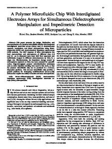
physical patterning approaches obtain cell patterns by capturing and confining cells in microfabricated mechanical structures such as microwells [6,14,24–27] and micro traps [28–30]. With optimized size and shape, these mechanical structures could perform high efficiency for cell patterning at single cell level [27,30]. However, there are still some limitations in the direct use of these mechanical methods in research such as cell migration, spreading, proliferation and polarization, as the topographic constraints that the mechanical structures bring may affect the growth of the cells. On the other hand, chemical cell patterning methods utilize selective attachment of randomly seeded cells on cell adhesive materials such as Poly-L-lysine (PLL) and adhesive proteins [10,31–35]. With the assistance of cell repellent materials to block the adjacent areas of the adhesive patterns, cells can be chemically confined in specific areas and form well defined patterns. Bashir’s group successfully demonstrated chemical cell patterning on fully suspended resonant sensors for measurement of cell mass during their growth [33], showing great versatility of chemical cell patterning. Although chemical cell patterning is free of topographic constraints, it usually needs complex chemical modifications, such as pre-coating and back filling of cell repellent materials. These chemical modifications may cause a residual toxicity, and are difficult for biologists. Additionally, chemical constraint applied by cell repellent materials prevents the revealing of the cells’ natural characteristics, especially in cell migration and proliferation applications. Some other chemical approaches pattern cells without cell repellent materials [15,36,37]. Millet et al. fabricated patterns and gradients of adhesive proteins by microfluidics-based substrate deposition, which successfully guided neuronal development [37]. These approaches were usually used in neuron science research, as neurons are known to be fragile and hard to attach to the substrate without adhesive materials. Besides, cell patterning methods combining physical and chemical approaches have also been developed [38–41]. Ostuni et al. reported a convenient method for cell patterning using microwells coated by fibronectin, a commonly used cell adhesive protein [38]. Cells deposited, attached and grew on the adhesive area in the microwells, while the microwells limited their spreading, migration and proliferation. Rodriguez’s group recently reported a novel single cell patterning system using hydrodynamic traps and protein patterns in a microfluidic device [40]. However, the fabrication of the delicate sieve-like cell traps is complex. The micro trap will restrict the growth of the cells if they are not removed after cell attachment, while the removing step may bring damages and risks of contamination to the cells. Herein, we developed a simple microfluidic chip for cell patterning, combining both physical microwells and chemical protein patterns in the same enclosed microfluidic channel. Microwells on the ceiling were designed for rapid and efficient cell capture at single cell level (or small numbers of cells), and protein patterns on the floor were for preferential cell attachment and growth (Figure 1). Cells were first loaded into the channel and captured by the microwells with the chip facing down; captured cells were then released from microwells and settled onto the protein patterns under gravity after a simple flipping of the chip. The whole cell patterning operation can be finished in 5 min. Two cancer cell lines—HeLa and human gallbladder carcinoma cells (SGC-996)—were used to demonstrate and analyze the patterning performance of our chip. Cell migration, cell proliferation and colony formation of both types of cells were successfully observed. With a main strategy of “capturing and releasing”, cells were positioned and patterned without complicated experiment setup or external forces except gravity, compared with inkjet-based, optical and dielectrophoresis approaches. Our device is free of topographic constraint compared with physical patterning approaches utilizing mechanical structures, and has no chemical confinement in contrast to some chemical patterning approaches. Furthermore, both microwells and micro contact printing (µCP) used in our device can be simply implemented in most biology laboratories after the fabrication of the master and no chemical surface modifications or specific experiences are needed, making our device a simple, fast and easy-to-operate method of cell patterning in a microfluidic device.
Micromachines 2017, 8, 1 Micromachines 2017, 7, 1
3 of 15
3 of 15
Figure 1. 1. Schematic protein patterns patternspaired pairedwith withtriangular triangular microwells. Figure Schematicofofthe themicrofluidic microfluidic chip chip with with protein microwells. Not to scale. Cells areare captured within thethe microwells in in thethe first step while these wells areare flipped onto Not to scale. Cells captured within microwells first step while these wells flipped theonto floor.the After flipping again, captured cells leave from the microwells and fall onto the corresponding floor. After flipping again, captured cells leave from the microwells and fall onto the protein patterns protein under gravity. Both the inletBoth and the outlet the before secondthe flipping corresponding patterns under gravity. inletare andsealed outletbefore are sealed second to minimize perturbations of flow inside of theflow channel. of the whole chip; (B)whole a tilted, flippingpossible to minimize possible perturbations inside(A) theSchematic channel. (A) Schematic of the chip; (B)view a tilted, magnified of the channel structure. The(green proteincolored) patternson (green colored) on the magnified of the channelview structure. The protein patterns the floor are precisely floorwith are precisely paired with microwells colored) on the ceiling. paired the microwells (red the colored) on the(red ceiling.
2. Materials and Methods 2. Materials and Methods Micro Contact PrintingofofProtein Proteinon onthe theSubstrate Substrate 2.1.2.1. Micro Contact Printing Micro contactprinting printing(µCP) (μCP) was was employed employed to to print onon thethe Micro contact print PolyPoly-LL-lysine -lysine(PLL) (PLL)ororprotein protein substrate of the microchannel. Procedures were modified according to published method [32]. substrate of the microchannel. Procedures were modified according to published method A [32]. polydimethylsiloxane (PDMS) (DC-184, Dow corning, Midland, MI, USA) slab with an array of A polydimethylsiloxane (PDMS) (DC-184, Dow corning, Midland, MI, USA) slab with an array of pillars fabricated by standard lithography was used as a stamp. The pillars on the stamp were 120 pillars fabricated by standard lithography was used as a stamp. The pillars on the stamp were 120 µm μm in diameter and 40 μm in height. A glass coverslip (80340-3610, Citotest Labware Manufacturing in diameter and 40 µm in height. A glass coverslip (80340-3610, Citotest Labware Manufacturing Co., Ltd., Haimen, China) with a thickness of 150 μm was chosen as the substrate. Coverslips were Co., Ltd., Haimen, China) with a thickness of 150 µm was chosen as the substrate. Coverslips were sonicated in ethanol and deionized (DI) water sequentially and N2 dried before use. The surface of sonicated in ethanol and deionized (DI) water sequentially and N2 dried before use. The surface of the PDMS stamp was first treated with O2 plasma for 30 s to facilitate the spread and infiltration of thethe PDMS stamp was first treated with O plasma for 30 s to facilitate the spread and infiltration protein solution. Then, a drop of PLL 2(P4707, Sigma-Aldrich, St. Louis, MO, USA) solution at the of theconcentration protein solution. a drop of PLL (L2020, (P4707,Sigma-Aldrich) Sigma-Aldrich,solution St. Louis, USA)concentration, solution at the of 50Then, μg/mL, or Laminin at MO, the same concentration of 50 µg/mL, or Laminin (L2020, Sigma-Aldrich) solution at the same was added onto the stamp and incubated for 30 min at room temperature (Figure 2A).concentration, The stamp was added onto the observed stamp and for 30 min atthe room temperature 2A).the Theremaining stamp was was periodically toincubated not get dried during incubation. After(Figure removing periodically not get during the incubation. After was removing the solution, aobserved mild washtowith 0.01dried M phosphate-buffered saline (PBS) applied toremaining the coated solution, stamp a mild wash with 0.01 M phosphate-buffered was applied to the coated for two for two times. The stamp was then swept by N2saline mildly(PBS) and left to dry in a clean hood for 5stamp min (Figure times. stamp then swept by N2 mildly and left toon dry a clean hood for 5another min (Figure 2B). The To mark thewas position of the protein patterns printed theinsubstrate precisely, PDMS2B). same of pillar as patterns the stamp was reversible bonded on the other side ofPDMS the coverslip To slab markwith the the position the array protein printed on the substrate precisely, another slab with a marker thethe fabrication process (Figure 2C–E).on After theof coverslip with Oas 2 plasma theassame pillarduring array as stamp was reversible bonded the treating other side the coverslip a marker for 1 min, the stamp was aligned with the marker under a microscope and fully contacted to 1the during the fabrication process (Figure 2C–E). After treating the coverslip with O2 plasma for min, substrate for 5 min before removing. An inverted microscope customized as a simple triaxial the stamp was aligned with the marker under a microscope and fully contacted to the substrate for alignment wasAn employed facilitate thecustomized alignment. as a simple triaxial alignment system was 5 min before system removing. invertedtomicroscope Fluorescein isothiocyanate labeled poly-L-lysine (PLL-FITC) (P3069, Sigma-Aldrich) was used to employed to facilitate the alignment. optimize the micro contact printing procedures. Fluorescence images of different samples prepared Fluorescein isothiocyanate labeled poly-L-lysine (PLL-FITC) (P3069, Sigma-Aldrich) was used to with different procedures were acquired by the same microscope and electron multiplying charge optimize the micro contact printing procedures. Fluorescence images of different samples prepared coupled device (EMCCD) camera with the same settings. The florescence intensity and uniformity with different procedures were acquired by the same microscope and electron multiplying charge were analyzed to evaluate the qualities of the patterns. coupled device (EMCCD) camera with the same settings. The florescence intensity and uniformity were analyzed to evaluate the qualities of the patterns.
Micromachines 2017, 8, 1 Micromachines 2017, 7, 1
4 of 15 4 of 15
Figure Figure 2. 2. Fabrication Fabrication of of the the of of the the microfluidic microfluidic device device with with paired paired microwells microwells and and protein protein patterns. patterns. Schematics Schematics were were not not drawn drawn to to scale. scale. (A,B) (A,B) Stamp Stamp incubation incubation with with the the protein protein solution; solution; (C,D) (C,D) Printing Printing protein patterns on the substrate; (E,F) Protein patterns and microwells pairing with the help protein patterns on the substrate; (E,F) Protein patterns and microwells pairing with the help of of aa polydimethylsiloxane (PDMS) alignment marker. polydimethylsiloxane (PDMS) alignment marker.
2.2. 2.2. Fabrication Fabrication and and Preparation Preparation of of the the Microfluidic Microfluidic Chip Chip Standard soft lithography was employed to Standard soft lithography was employed to fabricate fabricatethe themicrofluidic microfluidic channel channelwith withmicrowells. microwells. First, First, aa layer layer of of SU-8 SU-8 photoresist photoresist (3050, (3050, MicroChem MicroChem Corp., Corp., Westborough, Westborough, MA, MA, USA) USA) with with aa height height of of 50 μm was patterned on a polished Si-wafer to form the mold of the microchannel. Then, a 50 µm was patterned on a polished Si-wafer to form the mold of the microchannel. Then, a second second layer of SU-8 SU-8photoresist photoresist with a height 40was μmpatterned was patterned on layer the first layerthetomicrowells. form the layer of with a height of 40ofµm on the first to form microwells. The were microwells were to be equilateral triangular threesizes different sizes The microwells designed todesigned be equilateral triangular with three with different (40, 50, 60 (40, µm 50, 60 μm in side length, respectively) in a 20 mm × 2 mm rectangular microchannel. Uncured PDMS in side length, respectively) in a 20 mm × 2 mm rectangular microchannel. Uncured PDMS at a at a weight ratio of 10:1 (base curing agent) was cast themold moldand andcured curedatat80 80◦°C on aa hotplate weight ratio of 10:1 (base andand curing agent) was cast ononthe C on hotplate for 1 h. Cured PDMS slabs were cut by a scalpel and carefully peeled off from the mold for 1 h. Cured PDMS slabs were cut by a scalpel and carefully peeled off from the moldmanually. manually. After flat head head needle needlewas wasused usedtotopunch punchthrough throughthe thePDMS PDMSslab slabtotoform form the inlet and outlet After that, that, aa flat the inlet and outlet of of microchannel. Finally, PDMS debris on the PDMS washed away by ethanol thethe microchannel. Finally, PDMS debris andand dustdust on the PDMS slabslab waswas washed away by ethanol and and DI water in sequence. The PDMS slab was then with aligned with thewith marker withofthe help of a DI water in sequence. The PDMS slab was then aligned the marker the help a customized customized microscope and bonded to the substrate with former printed protein patterns after an O2 microscope and bonded to the substrate with former printed protein patterns after an O2 plasma plasma treatment 30 s W at 29.6 W power (PDC-002, Inc., Ithaca, NY, (Figure USA) (Figure treatment for 30 sfor at 29.6 power (PDC-002, HarrickHarrick PlasmaPlasma Inc., Ithaca, NY, USA) 2D,E). 2D,E). To prevent the protein patterns on the substrate from being damaged, a piece of PDMS was To prevent the protein patterns on the substrate from being damaged, a piece of PDMS was covered on covered on the protein patterns before the plasma treatment. the protein patterns before the plasma treatment. The microchannel was incubated by 5 wt % bovine serum albumin (BSA) (V900933, SigmaThe microchannel was incubated by 5 wt % bovine serum albumin (BSA) (V900933, Sigma-Aldrich) Aldrich) solution for 30 min at room temperature to prevent cells from attaching to the microwells solution for 30 min at room temperature to prevent cells from attaching to the microwells immediately [42]. Bubbles in the microchannel, especially in the microwells, were carefully removed immediately [42]. Bubbles in the microchannel, especially in the microwells, were carefully removed by applying an occasionally changing flow of BSA solution. The microchannel was then washed with by applying an occasionally changing flow of BSA solution. The microchannel was then washed with 0.01 M PBS and stored in a clean hood before use. 0.01 M PBS and stored in a clean hood before use. 2.3. 2.3. Cell Cell Culture Culture and and Cell Cell Suspension Suspension Preparation Preparation HeLa cultured in complete Dulbecco’s Modified Eagle Medium (DMEM) (Cat. No. HeLa cells cellswere were cultured in complete Dulbecco’s Modified Eagle Medium (DMEM) 11995-065, Gibco™, Thermo Fisher Scientific, Waltham, MA, USA) supplemented with 10 vol % fetal (Cat. No. 11995-065, Gibco™, Thermo Fisher Scientific, Waltham, MA, USA) supplemented with bovine (FBS) (Cat. No. 10099-133, Gibco™, Thermo Fisher Scientific) and 1 vol %and Penicillin– 10 vol %serum fetal bovine serum (FBS) (Cat. No. 10099-133, Gibco™, Thermo Fisher Scientific) 1 vol % 2 Streptomycin (Cat. No. 15140-148, Gibco™, Thermo Fisher Scientific) in a 25 cm polystyrene flask (Cat. No. 430639, Corning Inc., Corning, NY, USA) at 37 °C and 5% CO2 in a humidified incubator
Micromachines 2017, 8, 1
5 of 15
Micromachines 2017, 7, 1
5 of 15
Penicillin–Streptomycin (Cat. No. 15140-148, Gibco™, Thermo Fisher Scientific) in a 25 cm2 polystyrene flask (Cat. No. 430639, Corning Inc., Corning, NY, USA) at 37 ◦ C and 5% CO2 in a humidified incubator (BB15, Thermo Fisher Scientific). SGC-996 cells were cultured in complete Roswell Park Memorial (BB15, Thermo Fisher Scientific). SGC-996 cells were cultured in complete Roswell Park Memorial Institute (RPMI) 1640 medium (Cat. No. 11875-119, Gibco™, Thermo Fisher Scientific) supplemented Institute (RPMI) 1640 medium (Cat. No. 11875-119, Gibco™, Thermo Fisher Scientific) supplemented with 10 vol % FBS and 1 vol % Penicillin–Streptomycin in the same culture condition. with 10 vol % FBS and 1 vol % Penicillin–Streptomycin in the same culture condition. All cells were passaged at 70%–80% confluence using 0.05% Trypsin-EDTA (Cat. No. 25300-054, All cells were passaged at 70%–80% confluence using 0.05% Trypsin-EDTA (Cat. No. 25300-054, Gibco™, Thermo Fisher Scientific) under the common passage protocol. Briefly, cells were first rinsed Gibco™, Thermo Fisher Scientific) under the common passage protocol. Briefly, cells were first rinsed twice with pre-warmed PBS, then 1 mL pre-warmed Trypsin-EDTA solution was added. After an twice with pre-warmed PBS, then 1 mL pre-warmed Trypsin-EDTA solution was added. After an incubation in a 37 °C incubator for 5 min, 1 mL complete culture medium was added to stop the incubation in a 37 ◦ C incubator for 5 min, 1 mL complete culture medium was added to stop the trypsinization. Cell suspension was then transferred into a conical tube and centrifuged for 5 min at trypsinization. Cell suspension was then transferred into a conical tube and centrifuged for 5 min 1000 rpm (STR16, Thermo Fisher Scientific). Supernatant was discarded and cells were resuspended at 1000 rpm (STR16, Thermo Fisher Scientific). Supernatant was discarded and cells were resuspended in complete culture medium and reseeded. Cell concentration was determined using a in complete culture medium and reseeded. Cell concentration was determined using a hemacytometer hemacytometer and was adjusted to the required concentration. Hoechst 33258 (Cat. No. H3569, and was adjusted to the required concentration. Hoechst 33258 (Cat. No. H3569, Molecular Probes, Molecular Probes, Eugene, OR, USA) was used to stain the nucleus of cells according to the operation Eugene, OR, USA) was used to stain the nucleus of cells according to the operation manual provided manual provided by the manufacturer. Briefly, cells were incubated in Hoechst 33258 solution at the by the manufacturer. Briefly, cells were incubated in Hoechst 33258 solution at the concentration concentration of 2 ◦μg/mL at 37 °C and 5% CO2 for 20–30 min before passage. Cells loaded into our of 2 µg/mL at 37 C and 5% CO2 for 20–30 min before passage. Cells loaded into our chip were chip were resuspended in D-Hanks buffer (GNM-14175, Genom, Hangzhou, China) with 0.02 wt % resuspended in D-Hanks buffer (GNM-14175, Genom, Hangzhou, China) with 0.02 wt % EDTA EDTA (E6758, Sigma-Aldrich). (E6758, Sigma-Aldrich).
2.4. Cell Loading and Experiment Setup 2.4. Cell Loading and Experiment Setup A syringe driven by a syringe pump (NE-4002, New Era Pump Systems Inc., Farmingdale, NY, A syringe driven by a syringe pump (NE-4002, New Era Pump Systems Inc., Farmingdale, NY, USA) was connected to the inlet of the chip via a 1/16” Peek Teflon tubing (Upchurch Scientific, Oak USA) was connected to the inlet of the chip via a 1/16” Peek Teflon tubing (Upchurch Scientific, Oak Harbor, WA, USA) and suitable fittings (Upchurch Scientific) to apply flows into the microchannel. Harbor, WA, USA) and suitable fittings (Upchurch Scientific) to apply flows into the microchannel. Cell suspension at a concentration of 4 × 1066 cells/mL was gently pipetted with a fine pipette tip and Cell suspension at a concentration of 4 × 10 cells/mL was gently pipetted with a fine pipette tip and aspirated into a 200 μL pipette tip soon after preparation. The tip was then inserted into the outlet of aspirated into a 200 µL pipette tip soon after preparation. The tip was then inserted into the outlet of the chip and a negative flow at the speed of 20 μL/min from the inlet was applied to load cells into the chip and a negative flow at the speed of 20 µL/min from the inlet was applied to load cells into the microchannel (Figure 3A). The tip was removed after full filling of the microchannel and the chip the microchannel (Figure 3A). The tip was removed after full filling of the microchannel and the chip was flipped for the first time with the upside facing down (Figure 3B). Subsequently, a positive flow was flipped for the first time with the upside facing down (Figure 3B). Subsequently, a positive flow from the inlet to the outlet was driven into the microchannel at the speed of 2 μL/min for 2 min to from the inlet to the outlet was driven into the microchannel at the speed of 2 µL/min for 2 min to improve the capture efficiency [25]. Then, the speed was increased to 20 μL/min for 2 min to wash improve the capture efficiency [25]. Then, the speed was increased to 20 µL/min for 2 min to wash away the uncaptured cells (Figure 3C). After that, the tubing at the inlet was removed and both the away the uncaptured cells (Figure 3C). After that, the tubing at the inlet was removed and both the inlet and the outlet were carefully sealed with PDMS films to stop unwanted flow. Finally, the chip inlet and the outlet were carefully sealed with PDMS films to stop unwanted flow. Finally, the chip was was flipped again to release captured cells out of the microwells onto the protein patterns under flipped again to release captured cells out of the microwells onto the protein patterns under gravity gravity (Figure 3D). (Figure 3D).
Figure 3. 3. Cell Cell loading loading processes. processes. Schematics Schematics were were not not drawn drawn to to scale. scale. (A) (A) Cell Cell suspension suspension was was loaded loaded Figure into the microchannel with the chip facing up; (B) cells settled in the microwells after the first flipping into the microchannel with the chip facing up; (B) cells settled in the microwells after the first flipping of the the chip; chip; (C) (D) cells cells dropped dropped on on the the of (C) cells cells settled settled in in the the microwells microwells after after aa fast fast flow flow of of 20 20 µL/min; μL/min; (D) protein patterns protein patterns after after the the second second flipping flipping of of the the chip. chip.
Micromachines 2017, 8, 1
6 of 15
2.5. Cell Culture in the Microfluidic Chip After cell loading, the chip was packaged into a petri dish with Parafilm (Bemis, Neenah, WI, USA) and transferred into the incubator. To slow down the evaporation of the medium, 1 mL of sterile DI water was added into the petri dish. Cells in the microfluidic chip were incubated for 12 h before the first change of the medium. PDMS films at the inlet and outlet of the chip were carefully removed and 30 µL of pre-warmed complete medium was added to the inlet. The medium in the outlet was carefully removed with a pipette two times to completely change the medium in the microchannel. Both the inlet and the outlet were then covered by PDMS films again. The chip was packed in a petri dish and transferred back into the incubator. The medium was replaced with flash medium every 12 h in the following days. Cells were imaged every day to analyze the growth. 2.6. Imaging and Cell Analysis An inverted epi-fluorescence microscope (DMI4000, Leica, Wetzlar, Germany) equipped with a high-speed EMCCD camera (iXon ultra 897, Andor Technology Ltd., Belfast, UK) was used to observe the cells and acquire all the images. ImageJ® (1.48v, National Institutes of Health, Bethesda, MD, USA) was used for image processing and analysis. Line scans of the fluorescence intensity were used to evaluate the quality of the PLL-FITC patterns. Cell size was measured manually with the help of ImageJ® . To analyze the capture efficiency, cells were counted manually. 3. Results and Discussion 3.1. Cell Patterning Microfluidic Device with Paired Microwells and Protein Patterns A microfluidic cell patterning device with precisely paired microwells and protein patterns in the same microchannel was fabricated for rapid single cell patterning as shown in Figure 1A. Microwells on the ceiling of the microchannel were used to capture cells while the protein patterns on the floor were used to support the adhesion and growth of cells. Equilateral triangular microwells were used for efficient single cell capture [27] and three designs of microwells with side lengths of 40, 50 and 60 µm and a depth of 40 µm were fabricated according to cell sizes used in this work. PLL and Laminin, which are commonly used to facilitate the adhesion of cells on substrate, were pre-patterned on the floor by µCP. The protein patterns were designed to be round with a diameter of 120 µm. The microwells and the protein patterns were paired correspondingly as shown in Figure 1B. The distance between the centers of two adjacent microwells or protein patterns was 200 µm, which was long enough to promote a sufficient separation of cells from each other and was also close enough for cell–cell interaction in the early days after cell loading [6]. Cells first captured in the microwells were positioned on the protein patterns undergoing gravity, simply by flipping the chip [25], and no extra releasing operation such as removing the capture structures [40], was needed. There are two main challenges in the fabrication of our device. First, it is not easy to achieve a precise alignment of the microwells and the protein patterns directly, due to the transparency of the patterns. We employed a PDMS slab as a marker to assist this process (Figure 2C–E). The PDMS marker had the same structure as the PDMS stamp to guarantee the accuracy and a proper size (50 mm × 20 mm) for easy handling. Figure 4A showed the top view of the completed device with precisely paired microwells and PLL-FITC patterns. Another challenge is to prevent the protein patterns being damaged during the oxygen plasma bonding, as early work has shown that the plasma could destroy the patterned protein [39]. The printed protein patterns were covered by another PDMS slice initially to avoid potential damage. According to our experiment, PLL-FITC patterns protected by the PDMS slab maintained a high fluorescence after a 30 s O2 plasma treatment, while exposed patterns disappeared, indicting a sufficient protection by this method (Figure 4B).
Micromachines 2017, 8, 1 Micromachines 2017, 7, 1
7 of 15 7 of 15
Figure 4. Device Device fabrication. fabrication. (A) (A) Overlapped Overlapped images images of of paired fluorescein isothiocyanate labeled poly-LL-lysine -lysine (PLL-FITC) (PLL-FITC) patterns patterns and and microwells within a microchannel. Scale Scale bar bar isis 100 100 μm; µm; (B) fluorescence image of a PLL-FITC pattern after a 30 s O22 plasma treatment with the right side covered by a piece of PDMS. Dotted circle shows the original shape of the pattern pattern before before O O22 plasma treatment. The Theprotected protectedright rightside side maintained high fluorescence while the exposed leftwas side was maintained high fluorescence while the exposed left side totally damaged. Scale bar is 100 totally damaged. Scale barµm. is 100 μm.
3.2. Optimization of the Micro Contact Printing The parametersofofµCP μCP were modified the literature [32]. Substrate material, The parameters were modified fromfrom thosethose in the in literature [32]. Substrate material, substrate substrate treatment and stamp preparation were tested and optimized. As the protein treatment and stamp preparation were tested and optimized. As the protein patterns printedpatterns by µCP printed by aμCP only have a thickness of several nanometers [43], and areunder transparent under a normal only have thickness of several nanometers [43], and are transparent a normal microscope, microscope, directofevaluation of their qualityWe is difficult. We printed as a visible direct evaluation their quality is difficult. printed PLL-FITC asPLL-FITC a visible indicator by indicator different by μCPand procedures and evaluated qualities, taking theintensity fluorescence intensity and µCPdifferent procedures evaluated their qualities,their taking the fluorescence and uniformity as uniformity two criteria. high fluorescence and uniform intensity fluorescence intensity wereasconsidered as two criteria.asPatterns with Patterns high andwith uniform were considered high-quality. high-quality. optimized procedures were andthat we they assumed were also Indirectly, theIndirectly, optimizedthe procedures were elected and weelected assumed werethat alsothey applicable for applicable for PLL and Laminin. PLL and Laminin. Glass a substrate in terms of patterning quality (Figure 5A,C). The Glass was was preferred preferredover overPDMS PDMSasas a substrate in terms of patterning quality (Figure 5A,C). fluorescence intensity from glass was much higher. The efficiency of the material transfer The fluorescence intensity from glass was much higher. The efficiency of the material transfer is is determined byhydrophobicities hydrophobicitiesand and protein bonding capabilities the stamp and the substrate determined by protein bonding capabilities of theofstamp and the substrate [44,45]. [44,45]. A highbonding protein capability bonding capability of theand substrate and lowerofcapability stampfor is A high protein of the substrate lower capability the stampof is the favorable favorable forefficiency. the transfer efficiency. Also,Oa2 sufficient O2 plasma treatment was to enhance the transfer Also, a sufficient plasma treatment was necessary tonecessary enhance the transfer the transfer ofonto PLL-FITC onto the glass(Figure substrate (Figure 5B,C). O 2 plasma treatment the glass of PLL-FITC the glass substrate 5B,C). O2 plasma treatment makes themakes glass substrate substrate more hydrophilic and facilitates the bonding of PLL-FITC theBesides, glass. Besides, direct more hydrophilic and facilitates the bonding of PLL-FITC with thewith glass. direct use of use the of the stamp without washing after incubation reduced the uniformity the protein patterns (Figure stamp without washing after incubation reduced the uniformity of theofprotein patterns (Figure 5C). 5C). was because residual PLL-FITC solution onstamp the stamp may concentrate into considerable This This was because residual PLL-FITC solution on the may concentrate into considerable high high concentration and even crystallize in some areas when the stamp was left to dry. A mild wash concentration and even crystallize in some areas when the stamp was left to dry. A mild wash to to stamp after coating showed a significant improvement of pattern uniformity (Figure thethe stamp by by PBSPBS after coating showed a significant improvement of pattern uniformity (Figure 5D), 5D), despite the intensity declining significantly, because PBS dissolved the residual PLL-FITC of despite the intensity declining significantly, because PBS dissolved the residual PLL-FITC of high high concentration, leaving a more uniformly coated surface. As a result, we adopted O 2 plasmaconcentration, leaving a more uniformly coated surface. As a result, we adopted O2 plasma-treated treated glass substrates and mild washed for the subsequent experiments. glass substrates and mild washed stamps stamps for the subsequent experiments.
Micromachines 2017, 8, 1 Micromachines 2017, 7, 1
8 of 15 8 of 15
Figure Fluorescenceimages imagesand andcorresponding corresponding line line scans micro contact Figure 5. 5. Fluorescence scans showing showingthe thequality qualityofofthe the micro contact printing (μCP) process using PLL-FITC different procedures.All Allthe theresults resultswere wereobtained obtainedwith withthe printing (µCP) process using PLL-FITC byby different procedures. the same settings of the microscope and electron multiplying charge coupled device (EMCCD) same settings of the microscope and electron multiplying charge coupled device (EMCCD) camera. (A) Micropatterns on an O2 plasma-treated PDMS substrate; (B) micropatterns on substrate a glass (A)camera. Micropatterns on an O2 plasma-treated PDMS substrate; (B) micropatterns on a glass 2 plasma treatment; (C) poor uniformity of micropattern on an O2 plasma-treated substrate without O without O2 plasma treatment; (C) poor uniformity of micropattern on an O2 plasma-treated glass glass substrate using a non-washed stamp, an average fluorescence 2278; substrate using a non-washed stamp, with an with average fluorescence intensityintensity of 12,922of±12,922 2278; ±(D) good (D) good uniformity and high contrast ratio of micropatterns on an O2 plasma-treated glass substrate uniformity and high contrast ratio of micropatterns on an O2 plasma-treated glass substrate using a using a mildly washed stamp, with an average fluorescence intensity of 3114 ± 262. Scale bars are 50 mildly washed stamp, with an average fluorescence intensity of 3114 ± 262. Scale bars are 50 µm. μm.
The lifespan of of thethe protein patterns The lifespan protein patternswas wastested testedtotobebeatatleast least7 7days. days.PLL-FITC PLL-FITCpatterns patternsprinted printed by theby optimized procedures were immersed in complete culture medium in the incubator for a week. the optimized procedures were immersed in complete culture medium in the incubator for a week. Fluorescence images of of thethe sample were taken every 2424 h with thethe same setting of of thethe microscope and Fluorescence images sample were taken every h with same setting microscope and EMCCD camera. The contrast, defined asratio the ratio of the intensity of the PLL-FITC patternsand andthe EMCCD camera. The contrast, defined as the of the intensity of the PLL-FITC patterns the intensity the background, taken a criterion(Figure (Figure6A). 6A). Degeneration Degeneration ofofthe intensity of theofbackground, waswas taken as as a criterion thefluorescence fluorescence intensity was observed in the first three days, as the contrast dropped from 1.9 to 1.4 (Figure 6B). This6B). intensity was observed in the first three days, as the contrast dropped from 1.9 to 1.4 (Figure degradation waswas possibly due todue the to quenching of the fluorescence group and group diffusion of diffusion PLL-FITC of This degradation possibly the quenching of the fluorescence and into the medium. Despite the degeneration, the contrast still remained at around 1.4 times the in PLL-FITC into the medium. Despite the degeneration, the contrast still remained at around 1.4 in times following days and clear patterns could be observed (Figure 6C). The result showed that PLL-FITC the following days and clear patterns could be observed (Figure 6C). The result showed that PLL-FITC patterns substrate inculture the culture mediums degenerated overwhile time maintaining while maintaining an patterns on on the the substrate in the mediums degenerated over time an adequate adequate level after 7 days. level after 7 days.
Micromachines 2017, 8, 1 Micromachines 2017, 7, 1
9 of 15
9 of 15
Figure 6. 6. Lifespan ofof the PLL-FITC Figure Lifespan the PLL-FITCpatterns patternsininthe thecomplete completeculture culturemedium. medium. (A) (A) Curve Curve of of the the ratio ratio of theoffluorescence intensity of the PLL-FITC patterns to the fluorescence intensity of the background over the fluorescence intensity of the PLL-FITC patterns to the fluorescence intensity of the background 9 days; (B) fluorescence image of PLL-FITC patterns on Day 1; (C) fluorescence image of PLL-FITC over 9 days; (B) fluorescence image of PLL-FITC patterns on Day 1; (C) fluorescence image of PLLpatterns on Day on 6. Images were taken the same of the microscope and EMCCD camera. FITC patterns Day 6. Images werewith taken with thesettings same settings of the microscope and EMCCD Scale bars are 50bars µm.are 50 μm. camera. Scale
Cell Capture PerformanceDemonstrated Demonstratedwith with HeLa HeLa Cells Cells and 3.3.3.3. Cell Capture Performance and SGC-996 SGC-996Cells Cells Cells were patterned four steps with our device (Figure suspension loading; Cells were patterned byby four steps with our device (Figure 3):3): (1)(1) cellcell suspension loading; (2)(2) first first flipping of the chip to capture cells; (3) a fast flow to wash away uncaptured cells; and (4) second flipping of the chip to capture cells; (3) a fast flow to wash away uncaptured cells; and (4) second flipping to release the cells to the patterns. Figure 7A shows the Hoechst 33258 stained HeLa cells flipping to release the cells to the patterns. Figure 7A shows the Hoechst 33258 stained HeLa cells captured in the microwells after step (3), and Figure 7B shows HeLa cells on the protein patterns after captured in the microwells after step (3), and Figure 7B shows HeLa cells on the protein patterns after step (4). The whole cell patterning process can be finished in 5 min—faster than common passive cell step (4). The whole cell patterning process can be finished in 5 min—faster than common passive patterning methods—by selective attachment of cells, and by methods including inkjet printing, cell patterning methods—by selective attachment of cells, and by methods including inkjet printing, optical tweezers, dielectrophoresis and laser-directed cell writing. Although the microwells were optical tweezers, dielectrophoresis and laser-directed cell writing. Although the microwells were incubated with BSA prior to use, cells might be retained in the microwells if step (2) and (3) take a incubated with BSA prior to use, cells might be retained in the if step (2)could and (3) a long long time. According to our experiment results, more than 95%microwells of the captured cells be take released time. According to our experiment results, more than 95% of the captured cells could be released if the if the operation time of step (2) and (3) was less than 3 min. operation time ofSGC-996 step (2) cells and (3) was lesstothan 3 min. the capture performances of our devices with HeLa and were used characterize HeLa and SGC-996 cells were used to characterize capture performances of ourOur devices with three types of microwells with side lengths of 40 μm, the 50 μm and 60 μm, respectively. results three typesthat of microwells with side lengths of by 40 both µm, sizes 50 µm 60 µm, respectively. Our results showed capture efficiency was influenced of and the microwells and the cells. Images showed that capture efficiency was influenced both sizesand of the microwells andwas theanalyzed cells. Images of three random areas of the microwell arraysby were taken capture efficiency after of three of thesize microwell arraysand were taken and efficiency analyzed after cellrandom loading.areas For each of microwell each type ofcapture cell, five batches was of experiments werecell conducted, and size in total about 500and microwells were investigated for each batch of experiment. We loading. For each of microwell each type of cell, five batches of experiments were conducted, calculated the total efficiency tot), which was defined as theof ratio of microwells bythe and in total about 500capture microwells were(ηinvestigated for each batch experiment. We occupied calculated one or more cells over total wells, and the single cell capture efficiency (η s ), which was defined as the total capture efficiency (ηtot ), which was defined as the ratio of microwells occupied by one or more ratio of microwells a single amongefficiency all the microwells occupied by one or cells. of cells over total wells,occupied and theby single cellcell capture (ηs ), which was defined asmore the ratio For HeLa cells, when the side length of the microwells increased from 40 to 60 μm, the average microwells occupied by a single cell among all the microwells occupied by one or more cells. Fortotal HeLa capture efficiency went up from 43.9% ± 17.9% to 79.8% ± 5.8%, while the single cell capture efficiency cells, when the side length of the microwells increased from 40 to 60 µm, the average total capture droppedwent dramatically 86.4% ± 8.5%toto79.8% 35.9% ± ± 4.9% For SGC-996 cells, while ηs efficiency up fromfrom 43.9% ± 17.9% 5.8%,(Figure while 7C). the single cell capture efficiency showed a similar decrease trend as that of HeLa cells, ηtot first increased followed by a decrease when dropped dramatically from 86.4% ± 8.5% to 35.9% ± 4.9% (Figure 7C). For SGC-996 cells, while ηs the side length of the microwells increased from 40 to 60 μm (Figure 7D). According to our showed a similar decrease trend as that of HeLa cells, ηtot first increased followed by a decrease measurements, the average diameter of HeLa cells (15.5 ± 2.37 μm) was about 3 μm larger than that when the side length of the microwells increased from 40 to 60 µm (Figure 7D). According to our of SGC-996 cells (12.7 ± 2.13 μm). Consequently, the highest ηtot with HeLa cells (79.8% ± 5.8%) was measurements, the average diameter of HeLa cells (15.5 ± 2.37 µm) was about 3 µm larger than that of achieved in the largest microwells with a side length of 60 μm and the microwells with the highest SGC-996 cells (12.7 ± 2.13 µm). Consequently, highest ηtotBased withon HeLa (79.8% ± 5.8%) was ηtot for SGC-996 cells (73.7% ± 8.1%) were 50 μmthe in side length. this,cells we presume that larger achieved in the largest microwells with a side length of 60 µm and the microwells with the highest cells need microwells with longer side length for the highest ηtot, and the varied capture efficiencyηtot forbetween SGC-996 cells 8.1%) 50ofµm in different side length. on this, we presume that larger the two(73.7% types of±cells is awere result their sizes.Based In terms of single capture efficiency, cells need microwells with longer side length for the highest η , and the varied capture efficiency tot trends of the two types of cells were consistent, indicating that the size of the microwells rather than between the two types of cells is a result of their different sizes. In terms of single capture efficiency, the size of cells played a dominant role here. These results showed that the capture efficiency of our trends of was the two types ofoncells consistent, indicating that the microwells rather than device dependent bothwere the sizes of the microwells and the size cells.ofAs a compromise between the size of cells played a dominant role here. These results showed that the capture efficiency of our
Micromachines 2017, 8, 1
10 of 15
Micromachines 2017, 7, 1 10 of 15 device was dependent on both the sizes of the microwells and the cells. As a compromise between total total and single capture efficiency, we adopted microwells with 50 µm side length in the subsequent and single capture efficiency, we adopted microwells with 50 μm side length in the subsequent cell patterning experiments forfor both types cell patterning experiments both typesofofcells. cells.
Figure Cell capture performance. HeLa and gallbladder human gallbladder carcinoma cells (SGC-996) Figure 7. Cell7.capture performance. HeLa and human carcinoma cells (SGC-996) suspension at suspension at a concentration of 4 × 10⁶ cells/mL was used, respectively. (A) HeLa cells stained with 6 a concentration of 4 × 10 cells/mL was used, respectively. (A) HeLa cells stained with Hoechst 33258 Hoechst 33258 (cyan colored) were captured in the microwells after washing. Scale bar is 100 μm; (B) (cyan colored) were captured in the microwells after washing. Scale bar is 100 µm; (B) HeLa cells were HeLa cells were released from the microwells and fell on the protein patterns (non-fluorescently released from the microwells and fell on the protein patterns (non-fluorescently labeled). Note that labeled). Note that there was a distance of 50 μm from the microwells to the paired patterns, and the therefocus was aplane distance from the the microwells to the paired that patterns, and fallen the focus plane was of on 50 theµm microwells; blurred cells indicated they had out of the was on the microwells; the blurred cells(C,D) indicated that they had fallen out ofmicrowells the microwells. Scale microwells. Scale bar is 100 μm; cell capture efficiencies of triangle with three sidebar is 100 µm; (C,D)The celltotal capture efficiencies triangle with three The total capture lengths. capture efficiencyoffor HeLa microwells cells increased with theside sidelengths. length while a peak efficiency for HeLa cells increased with side length while a peak efficiency was achieved with 50 µm efficiency was achieved with 50 μmthe side length microwells for SGC-996 cells. The single capture efficiency for both types of cells dropped dramatically when efficiency the side length increased 40 todropped 60 side length microwells for SGC-996 cells. The single capture for both typesfrom of cells μm; (E,F) size distributions of the original cells and captured single cells by 50 μm side length dramatically when the side length increased from 40 to 60 µm; (E,F) size distributions of the original microwells of HeLa SGC-996 cells. Diameters of captured of HeLa single concentrated in a cells and captured singleand cells by 50 µm side length microwells HeLa andcells SGC-996 cells. Diameters range of 15–18 μm and 13–16 μm for captured SGC-996 cells, while the origin cells distributed in of captured HeLa single cells concentrated in a range of 15–18 µm and 13–16 µm for captured SGC-996 wider ranges. The average diameter of the captured single cells of both types increased while the cells, while the origin cells distributed in wider ranges. The average diameter of the captured single standard deviations dropped, implying a promoted uniformity of cell size. cells of both types increased while the standard deviations dropped, implying a promoted uniformity of cell size.
Micromachines 2017, 8, 1
11 of 15
We further investigated the influence of the capture process to the size distribution of the cells. We analyzed the diameter distribution of single cells captured by microwells with 50 µm side length and compared it with the original distribution (Figure 7E,F). A total of 158 captured HeLa cells, 152 captured SGC-996 cells and the same number of original cells were measured, respectively. Diameters of captured HeLa cells concentrated in a range of 15–18 µm, and 13–16 µm for SGC-996 cells, while the original diameter of both types of cells distributed in wider ranges. Besides, for both types of cells, the average diameter of captured cells increased, while the standard deviation dropped, from 15.5 ± 2.37 µm to 16.2 ± 1.54 µm for HeLa cells (Figure 7E), and 12.7 ± 2.13 µm to 14.2 ± 1.44 µm for SGC-996 cells (Figure 7F), indicating an improved uniformity of the size. Based on these observations, we presume that cell capture in our device is not a random process. During the cell loading process, a fast flow was applied to wash away the uncaptured cells. This flow also applied nonnegligible influences to cells captured in the microwells. For microwells with specific side length, cells in the microwells with improper size would be brought out by the fast flow more easily, contributing to the concentrated size distribution, increased average diameter and improved uniformity of the captured cells. The shifts of these cell size distributions imply that microwells with specific side length are prone to capture cells with relevant size, which may give our device the potential ability of cell size dependent screening. To quantify the final patterning yield and reproducibility of the device with 50 µm side length microwells, we calculated the ratio of the number of patterns occupied by cells to that of the total patterns (ηp ). Only cells that fell in the circular patterns with a diameter of 120 µm were considered to be well patterned. For each type of cells, three batches of experiments were conducted and three areas were picked randomly for the analysis. For HeLa cells, the average ηp of three experiments was 65.7% ± 10.1% (52.1%, 68.8% and 76.3%), and 71.1% ± 11.5% (56.3%, 72.9% and 84.2%) for SGC-996 cells. These results were consistent with the total capture efficiency of the same device for both types of cells (68.7% ± 10.6% for HeLa cells and 73.7% ± 8.1% for SGC-996 cells). Except the capture efficiency, two issues may decrease the patterning yield. The first one was that a few cells might be retained in the microwells, which could be overcome by a fine pretreatment of the microwells using BSA solution and a short operation time when capturing cells. Another one is that cells might be moved out of the protein patterns when falling from the microwells by the unwanted flow if the inlet and the outlet were not fully sealed. The circular patterns were designed larger than the microwells to counteract the slight position shift of the cells during the alignment, which was measured to be less than 30 µm in our device (Figure 7B). According to our observation, microwells 50 µm in side length with paired protein patterns 120 µm in diameter worked well. 3.4. Cell Patterning Performance with HeLa and SGC-996 Cells To demonstrate the cell patterning performance of our device, HeLa and SGC-996 cells were successfully patterned at single cell level in an array of round patterns with a diameter of 120 µm and spacing of 200 µm. Time-lapse images showed that HeLa and SGC-996 cells successfully survived for at least 6 days in our device and the migration, proliferation and colony formation of both cell types were observed (Figure 8). After loading, cells were cultured in the microchannel in the incubator with FBS-free medium for 12 h before the medium in the microchannel was replaced with fresh complete culture medium. During the first 12 h, most of the cells completed the attachment and some of them began to spread and proliferate on the protein patterns. As there was no FBS in the medium, it was mainly the protein patterns that supported the attachment of the cells as extracellular matrix (ECM) materials. Then, the medium was replaced every 12 h with complete culture medium supplemented with 10 vol % FBS to support cell growth. The growth could be loosely divided into two typical stages for both cell types. In the first stage (Figure 8, Day 0 to Day 2), cells attached to the protein patterns and divided into small cell clusters containing two or more cells; a few cells migrated out of the patterns. In the second stage (Figure 8, Day 3 to Day 5), the proliferation sped up obviously and cell colonies formed gradually. Besides, cells also began to migrate out of the protein patterns to establish
Micromachines 2017, 8, 1
12 of 15
Micromachines 2017, 7, 1
12 of 15
connections with adjacent cells in this stage. According to these results, cell–material interactions might mightbe beessential essentialto tocell cellattachment attachmentand andproliferation proliferationduring duringthe thefirst firststage, stage,and andcell–cell cell–cellinteractions interactions of adjacent cells could play a more important role in the second stage. of adjacent cells could play a more important role in the second stage.
Figure Figure8.8.Time-lapse Time-lapsephase phasecontrast contrastimages imagesof ofHeLa HeLacells cellsand andSGC-996 SGC-996cells cellsgrowing growingon onPLL PLLpatterns patterns in in our our device. device. (A) (A)Patterning Patterningperformance performancewith withHeLa HeLacells cellson on the the PLL PLL patterns patterns (non-fluorescently (non-fluorescently labeled) to DAY DAY5.5.Scale Scalebar barisis100 100µm; μm;(B) (B)patterning patterning performance with SGC-996 cells labeled) from from DAY 0 to performance with SGC-996 cells on on PLL patterns (non-fluorescently labeled) from DAY to DAY 6. Scale is 100 thethe PLL patterns (non-fluorescently labeled) from DAY 1 to1DAY 6. Scale barbar is 100 µm.μm.
Compared based on on physical structures, suchsuch as microwells and Compared with withcell cellpatterning patterningdevices devices based physical structures, as microwells micro sieves,sieves, our device is free of constraint in the micro environment around patterned and micro our device is topographic free of topographic constraint in the micro environment around cells, which may hinder the spreading, migration and proliferation. Also, the absence of topographic patterned cells, which may hinder the spreading, migration and proliferation. Also, the absence of constraint brings a higher medium exchange efficiency, which plays which an important in cell–cell topographic constraint brings a higher medium exchange efficiency, plays anrole important role interaction diffusiblebysignaling [6,46]. Furthermore, cells were first captured and then transferred in cell–cell by interaction diffusible signaling [6,46]. Furthermore, cells were first captured and then onto the protein in our device, is different devicesfrom utilizing selective attachment transferred ontopatterns the protein patterns inwhich our device, whichfrom is different devices utilizing selective of cells. No cell attachment materials such as poly(ethylene glycol) (PEG) were(PEG) needed to attachment of cells. No cell repellent attachment repellent materials such as poly(ethylene glycol) were chemically restrict cells in specific areas, so that complex chemical modifications were avoided. Cells needed to chemically restrict cells in specific areas, so that complex chemical modifications were can grow more freely andmore morefreely closely, characteristics in natural conditions. According to avoided. Cells can grow andreflecting more closely, reflecting characteristics in natural conditions. our observation, presentedHeLa longer cell bodies, andcell more long and pseudopodia out According to ourHeLa observation, presented longer bodies, more longprotruded pseudopodia (Figure 8A, Day 1), while SGC-996 maintained polygonal cell bodies with a few short pseudopodia protruded out (Figure 8A, Day 1), while SGC-996 maintained polygonal cell bodies with a few short (Figure 8B, Day 1). Besides, HeLa cells showed moreshowed aggressive migration capability thancapability SGC-996 pseudopodia (Figure 8B, Day 1). Besides, HeLaa cells a more aggressive migration cells were cells moreand prone to more connect with other (Figure Day 2), while SGC-996 cellsSGC-996 tended thanand SGC-996 were prone toeach connect with each 8A, other (Figure 8A, Day 2), while to form cell colonies by themselves (Figure 8B, Day 2), suggesting that HeLa cells may have stronger cells tended to form cell colonies by themselves (Figure 8B, Day 2), suggesting that HeLa cells may cell interactions with each other. In addition, different characters were also observed among individual cells of the same cell type. These results demonstrated the ability of our device in the study of cell attachment, migration, proliferation, colony formation and cellular heterogeneity.
Micromachines 2017, 8, 1
13 of 15
have stronger cell interactions with each other. In addition, different characters were also observed among individual cells of the same cell type. These results demonstrated the ability of our device in the study of cell attachment, migration, proliferation, colony formation and cellular heterogeneity. The main strategy of our device can be summarized into “capturing–releasing”, which takes both advantages of microwells and protein patterns. Microwells provide an easy way to position cells into a desired layout at single cell level with a high throughput, and protein patterns provide suitable extracellular matrix materials for cells to undergo biological processes. An easy way that one may think of in the first place is to pattern cells in a substrate coated with uniform cell adhesive materials. Compared with our device, this method lacks intrinsic capacities of the protein patterns in cell biological research such as cell–material interaction, cell shape engineering and neuron network formation, resulting in a limited application. In this work, we used spaced round patterns of PLL and Laminin as a demonstration. The layout and shape of the patterns can be easily verified by utilizing different stamps. Furthermore, different materials, including cell repellent materials, can be patterned to enhance the ability of our device in the research of cell–material interaction and guided neuron network formation in our future work. 4. Conclusions In conclusion, we successfully demonstrated a simple, fast and precise way for cell patterning in a microfluidic chip without utilizing cell selective attachment or cell repellent materials. The microchip incorporated with a paired array of microwells and protein patterns was fabricated following the optimized procedures to capture and transfer cells into designed positions. HeLa and SGC-996 cells were patterned on the PLL or Laminin patterns in 5 min at single cell level and survived for 6 days. Cell attachment, migration, proliferation and colony formation for both types of cells were observed. We also analyzed the influence of the sizes of microwells and cells to the capture performance, which is helpful for research using other cell types. Without topographic constraint to the patterned cells and complex chemical modifications, this simple, fast and efficient cell patterning method provides a convenient approach for cell biology research which are sensitive to the initial cell position and extracellular environment, such as single cell analysis, cell–material interaction, cell–cell interaction, cell co-culture, drug screening, cell colony formation and guided formation of the neuron network. Acknowledgments: This research was funded by the National Science Foundation of China under grant No. 81501614 and No. 61501400. We also acknowledge support from Health and Family Planning Commission of Zhejiang Province (No. 2014RCA010), China Postdoctoral Science Foundation (2015M571879) and Special Foundation of China Postdoctoral Science (2016T90541). Author Contributions: All of the authors have provided substantial contributions to the conception and design of the device, conducting of the experiments, acquisition of the data, analysis of the data and writing of the manuscript. Conflicts of Interest: The authors declare no conflict of interest.
References 1. 2.
3. 4. 5.
Csucs, G.; Quirin, K.; Danuser, G. Locomotion of fish epidermal keratocytes on spatially selective adhesion patterns. Cell Motil. Cytoskelet. 2007, 64, 856–867. [CrossRef] [PubMed] Xia, N.; Thodeti, C.K.; Hunt, T.P.; Xu, Q.B.; Ho, M.; Whitesides, G.M.; Westervelt, R.; Ingber, D.E. Directional control of cell motility through focal adhesion positioning and spatial control of rac activation. FASEB J. 2008, 22, 1649–1659. [CrossRef] [PubMed] Thery, M.; Racine, V.; Pepin, A.; Piel, M.; Chen, Y.; Sibarita, J.B.; Bornens, M. The extracellular matrix guides the orientation of the cell division axis. Nat. Cell Biol. 2005, 7, 947–953. [CrossRef] [PubMed] Scott, M.A.; Wissner-Gross, Z.D.; Yanik, M.F. Ultra-Rapid laser protein micropatterning: Screening for directed polarization of single neurons. Lab Chip 2012, 12, 2265–2276. [CrossRef] [PubMed] Desai, R.A.; Gao, L.; Raghavan, S.; Liu, W.F.; Chen, C.S. Cell polarity triggered by cell-cell adhesion via e-cadherin. J. Cell Sci. 2009, 122, 905–911. [CrossRef] [PubMed]
Micromachines 2017, 8, 1
6. 7. 8.
9. 10. 11.
12. 13.
14.
15. 16.
17. 18. 19. 20. 21. 22. 23. 24. 25.
26.
27.
28.
14 of 15
Rosenthal, A.; Macdonald, A.; Voldman, J. Cell patterning chip for controlling the stem cell microenvironment. Biomaterials 2007, 28, 3208–3216. [CrossRef] [PubMed] Chen, C.S.; Mrksich, M.; Huang, S.; Whitesides, G.M.; Ingber, D.E. Geometric control of cell life and death. Science 1997, 276, 1425–1428. [CrossRef] [PubMed] Ho, C.T.; Lin, R.Z.; Chen, R.J.; Chin, C.K.; Gong, S.E.; Chang, H.Y.; Peng, H.L.; Hsu, L.; Yew, T.R.; Chang, S.F.; et al. Liver-Cell patterning lab chip: Mimicking the morphology of liver lobule tissue. Lab Chip 2013, 13, 3578–3587. [CrossRef] [PubMed] Khademhosseini, A.; Langer, R.; Borenstein, J.; Vacanti, J.P. Microscale technologies for tissue engineering and biology. Proc. Natl. Acad. Sci. USA 2006, 103, 2480–2487. [CrossRef] [PubMed] Hardelauf, H.; Waide, S.; Sisnaiske, J.; Jacob, P.; Hausherr, V.; Schobel, N.; Janasek, D.; van Thriel, C.; West, J. Micropatterning neuronal networks. Analyst 2014, 139, 3256–3264. [CrossRef] [PubMed] Takayama, Y.; Kotake, N.; Haga, T.; Suzuki, T.; Mabuchi, K. Formation of one-way-structured cultured neuronal networks in microfluidic devices combining with micropatterning techniques. J. Biosci. Bioeng. 2012, 114, 92–95. [CrossRef] [PubMed] Mrksich, M.; Whitesides, G.M. Patterning self-assembled monolayers using microcontact printing: A new technology for biosensors? Trends Biotechnol. 1995, 13, 228–235. [CrossRef] Hynes, W.F.; Doty, N.J.; Zarembinski, T.I.; Schwartz, M.P.; Toepke, M.W.; Murphy, W.L.; Atzet, S.K.; Clark, R.; Melendez, J.A.; Cady, N.C. Micropatterning of 3D microenvironments for living biosensor applications. Biosensors 2014, 4, 28–44. [CrossRef] [PubMed] Liu, Z.B.; Zhang, Y.; Yu, J.J.; Mak, A.F.T.; Li, Y.; Yang, M. A microfluidic chip with poly(ethylene glycol) hydrogel microarray on nanoporous alumina membrane for cell patterning and drug testing. Sens. Actuators B Chem. 2010, 143, 776–783. [CrossRef] Millet, L.J.; Gillette, M.U. New perspectives on neuronal development via microfluidic environments. Trends Neurosci. 2012, 35, 752–761. [CrossRef] [PubMed] Weaver, W.M.; Tseng, P.; Kunze, A.; Masaeli, M.; Chung, A.J.; Dudani, J.S.; Kittur, H.; Kulkarni, R.P.; Di Carlo, D. Advances in high-throughput single-cell microtechnologies. Curr. Opin. Biotechnol. 2014, 25, 114–123. [CrossRef] [PubMed] Yusof, A.; Keegan, H.; Spillane, C.D.; Sheils, O.M.; Martin, C.M.; O’Leary, J.J.; Zengerle, R.; Koltay, P. Inkjet-Like printing of single-cells. Lab Chip 2011, 11, 2447–2454. [CrossRef] [PubMed] Ozkan, M.; Pisanic, T.; Scheel, J.; Barlow, C.; Esener, S.; Bhatia, S.N. Electro-Optical platform for the manipulation of live cells. Langmuir 2003, 19, 1532–1538. [CrossRef] Zhang, H.; Liu, K.K. Optical tweezers for single cells. J. R. Soc. Interface 2008, 5, 671–690. [CrossRef] [PubMed] Rosenthal, A.; Voldman, J. Dielectrophoretic traps for single-particle patterning. Biophys J. 2005, 88, 2193–2205. [CrossRef] [PubMed] Gray, D.S.; Tan, J.L.; Voldman, J.; Chen, C.S. Dielectrophoretic registration of living cells to a microelectrode array. Biosens. Bioelectron. 2004, 19, 1765–1774. [CrossRef] Odde, D.J.; Renn, M.J. Laser-Guided direct writing of living cells. Biotechnol. Bioeng. 2000, 67, 312–318. [CrossRef] Schiele, N.R.; Corr, D.T.; Huang, Y.; Raof, N.A.; Xie, Y.; Chrisey, D.B. Laser-based direct-write techniques for cell printing. Biofabrication 2010, 2, 032001. [CrossRef] [PubMed] Rettig, J.R.; Folch, A. Large-Scale single-cell trapping and imaging using microwell arrays. Anal. Chem. 2005, 77, 5628–5634. [CrossRef] [PubMed] Lin, C.-H.; Hsiao, Y.-H.; Chang, H.-C.; Yeh, C.-F.; He, C.-K.; Salm, E.M.; Chen, C.; Chiu, I.-M.; Hsu, C.-H. A microfluidic dual-well device for high-throughput single-cell capture and culture. Lab Chip 2015, 15, 2928–2938. [CrossRef] [PubMed] Khademhosseini, A.; Ferreira, L.; Blumling, J., 3rd; Yeh, J.; Karp, J.M.; Fukuda, J.; Langer, R. Co-Culture of human embryonic stem cells with murine embryonic fibroblasts on microwell-patterned substrates. Biomaterials 2006, 27, 5968–5977. [CrossRef] [PubMed] Park, J.Y.; Morgan, M.; Sachs, A.N.; Samorezov, J.; Teller, R.; Shen, Y.; Pienta, K.J.; Takayama, S. Single cell trapping in larger microwells capable of supporting cell spreading and proliferation. Microfluid. Nanofluid. 2010, 8, 263–268. [CrossRef] [PubMed] Di Carlo, D.; Wu, L.Y.; Lee, L.P. Dynamic single cell culture array. Lab Chip 2006, 6, 1445–1449. [CrossRef] [PubMed]
Micromachines 2017, 8, 1
29. 30. 31. 32. 33.
34. 35. 36. 37.
38. 39. 40. 41.
42.
43. 44. 45. 46.
15 of 15
Skelley, A.M.; Kirak, O.; Suh, H.; Jaenisch, R.; Voldman, J. Microfluidic control of cell pairing and fusion. Nat. Methods 2009, 6, 147–152. [CrossRef] [PubMed] Zhang, K.; Chou, C.K.; Xia, X.; Hung, M.C.; Qin, L. Block-Cell-Printing for live single-cell printing. Proc. Natl. Acad. Sci. USA 2014, 111, 2948–2953. [CrossRef] [PubMed] Kane, R.S.; Takayama, S.; Ostuni, E.; Ingber, D.E.; Whitesides, G.M. Patterning proteins and cells using soft lithography. Biomaterials 1999, 20, 2363–2376. [CrossRef] Théry, M.; Piel, M. Adhesive micropatterns for cells: A microcontact printing protocol. Cold Spring Harb. Protoc. 2009, 2009. [CrossRef] [PubMed] Corbin, E.A.; Dorvel, B.R.; Millet, L.J.; King, W.P.; Bashir, R. Micro-Patterning of mammalian cells on suspended MEMS resonant sensors for long-term growth measurements. Lab Chip 2014, 14, 1401–1404. [CrossRef] [PubMed] Millet, L.J.; Collens, M.B.; Perry, G.L.; Bashir, R. Pattern analysis and spatial distribution of neurons in culture. Integr. Biol. Quant. Biosci. Nano Macro 2011, 3, 1167–1178. [CrossRef] [PubMed] Jing, G.; Perry, S.F.; Tatic-Lucic, S. Precise cell patterning using cytophobic self-assembled monolayer deposited on top of semi-transparent gold. Biomed. Microdevices 2010, 12, 935–948. [CrossRef] [PubMed] Shi, P.; Nedelec, S.; Wichterle, H.; Kam, L.C. Combined microfluidics/protein patterning platform for pharmacological interrogation of axon pathfinding. Lab Chip 2010, 10, 1005–1010. [CrossRef] [PubMed] Millet, L.J.; Stewart, M.E.; Nuzzo, R.G.; Gillette, M.U. Guiding neuron development with planar surface gradients of substrate cues deposited using microfluidic devices. Lab Chip 2010, 10, 1525–1535. [CrossRef] [PubMed] Ostuni, E.; Chen, C.S.; Ingber, D.E.; Whitesides, G.M. Selective deposition of proteins and cells in arrays of microwells. Langmuir 2001, 17, 2828–2834. [CrossRef] Rhee, S.W.; Taylor, A.M.; Tu, C.H.; Cribbs, D.H.; Cotman, C.W.; Jeon, N.L. Patterned cell culture inside microfluidic devices. Lab Chip 2005, 5, 102–107. [CrossRef] [PubMed] Lin, L.; Chu, Y.-S.; Thiery, J.P.; Lim, C.T.; Rodriguez, I. Microfluidic cell trap array for controlled positioning of single cells on adhesive micropatterns. Lab Chip 2013, 13, 714–721. [CrossRef] [PubMed] Torisawa, Y.S.; Mosadegh, B.; Luker, G.D.; Morell, M.; O’Shea, K.S.; Takayama, S. Microfluidic hydrodynamic cellular patterning for systematic formation of co-culture spheroids. Integr. Biol. Quant. Biosci. Nano Macro 2009, 1, 649–654. [CrossRef] [PubMed] Chiu, D.T.; Jeon, N.L.; Huang, S.; Kane, R.S.; Wargo, C.J.; Choi, I.S.; Ingber, D.E.; Whitesides, G.M. Patterned deposition of cells and proteins onto surfaces by using three-dimensional microfluidic systems. Proc. Natl. Acad. Sci. USA 2000, 97, 2408–2413. [CrossRef] [PubMed] Huang, L.R.; Cox, E.C.; Austin, R.H.; Sturm, J.C. Continuous particle separation through deterministic lateral displacement. Science 2004, 304, 987–990. [CrossRef] [PubMed] Tan, J.L.; Tien, J.; Chen, C.S. Microcontact printing of proteins on mixed self-assembled monolayers. Langmuir 2002, 18, 519–523. [CrossRef] Alom Ruiz, S.; Chen, C.S. Microcontact printing: A tool to pattern. Soft Matter 2007, 3, 168–177. [CrossRef] Walker, G.M.; Zeringue, H.C.; Beebe, D.J. Microenvironment design considerations for cellular scale studies. Lab Chip 2004, 4, 91–97. [CrossRef] [PubMed] © 2016 by the authors; licensee MDPI, Basel, Switzerland. This article is an open access article distributed under the terms and conditions of the Creative Commons Attribution (CC-BY) license (http://creativecommons.org/licenses/by/4.0/).