cess for model transformations based on this semantics, and we describe ..... cases, one to check the validity of the source model and the other to carry out.
A Model-based Development approach for Model Transformations S. Kolahdouz-Rahimi, K. Lano Dept. of Informatics, King’s College London, Strand, London, UK
Abstract. Model transformations have become a key element of modeldriven software development, being used to transform platform-independent models (PIMs) to platform-specific models (PSMs), to improve model quality, to introduce design patterns and refactorings, and to map models from one language to another. A large number of model transformation notations and tools exist, however, there remain substantial problems concerning the analysis and verification of model transformations. In particular, there is no systematic development process for model transformations. In this paper, we provide a unified semantic treatment of model transformations, and show how correctness properties of model transformations can be defined. We define a systematic model-driven development process for model transformations based on this semantics, and we describe case studies using this process.
1
Introduction
Model transformations are mappings of one or more software engineering models (source models) into one or more target models. The models considered may be graphically constructed using graphical languages such as the Unified Modelling Language (UML) [18], or can be textual notations such as programming languages or formal specification languages. The research area of model transformations remains very active, and certain fundamental issues have as yet only partially been solved: Specification issues Semantically, model transformations can be considered to be relations between (the sets of models of) languages, ie., in the binary case, they identify for a pair (M1 , M2 ) of models of two languages, if M1 is related by the transformation to M2 . But for convenience transformations are usually defined by sets of transformation rules which relate specific elements of M1 to specific elements of M2 . This introduces problems of dependency and consistency between rules, and the overall effect of the set of rules may be difficult to deduce from the rules themselves, either for a human reader, or for analysis and verification tools [23]. These problems are akin to those of other software technologies, such as rewrite-rule based systems and knowledge-based systems, which describe global processes by collections of localised rules.
Development issues At present, construction of model transformations is focussed upon the implementation of a transformation in a particular model transformation language [6], the transformation is described only at a relatively low level of abstraction, without a separate specification. The development process may be ad-hoc, without systematic guidelines on how to structure transformations. The plethora of different transformation languages creates problems of migration and reuse of transformations from one language to another. Ironically, the model transformation community has recreated the development problems, for this specialised form of software, which model-driven development (MDD) was intended to ameliorate: the inability to reuse and migrate systems due to the lack of platform-independent specifications, and an excessive implementation focus [7]. The solution which we propose to these problems is to adopt a general modeldriven software development approach, UML-RSDS (Reactive System Development Support) [14], for model transformation development. UML-RSDS provides the necessary specification notations for model transformation definition, at different levels of abstraction, and provides support for verification and the synthesis of executable code. UML-RSDS uses standardised UML notation and concepts, so permitting reuse and communication of models. We consider the following kinds of model transformation: Refinement transformations are used to refine a model towards an implementation. For example, PIM to PSM transformations in the Model-driven Architecture (MDA). Re-expressions translate a model in one language into its ‘nearest equivalent’ in a different language. This includes model migration. Transformations which perform some analysis upon the source model and construct analysis results, such as checking or model comparison transformations, can be considered as abstractions. Quality improvement transformations transform a model to improve its structure. Within each category, further subcategories can be distinguished, for example refactoring is a particular subcategory of quality improvement transformation. Section 2 defines a general semantics for model transformations and defines concepts of correctness for model transformations. Section 3 surveys techniques for the definition of transformations. Section 4 describes the UML-RSDS language and the elements of our model transformation development process using UML-RSDS. Section 5 describes the application of the process to the specification and design of transformation case studies. Finally in Section 7 we summarise our recommendations for improving the development of model transformations.
2 2.1
Semantic framework for model transformations Metamodelling framework
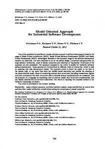
We will consider transformations between languages specified using the MetaObject Framework (MOF). Figure 1 shows the four-level metamodelling frame-
work of UML using MOF. At each level, a model or structure can be considered to be an instance of a structure at the next higher level.
M3 (MOF)
Class
M2 (UML)
Property
Class
M1 (User model)
Person name: String
M0 (Run−time instances)
p1
Fig. 1. UML metamodel levels
In discussing model transformation correctness, we will refer to the M2 level as the language level (the models define the languages which the transformation relates) and to the M1 level as the model level (the models which the transformation operates upon). For each model M at levels M2 and M3, we can define (i) a logical language LM that corresponds to M , and (ii) a logical theory ΓM in LM , which defines the semantic meaning of M , including any internal constraints of M . If an M1 model is also a UML model, it can also be assigned such a language and theory. LM and ΓM are defined using the axiomatic semantics for UML given in Chapter 6 of [16], based upon structured theories and theory morphisms in a real-time temporal logic. LM consists of type symbols for each type defined in M , including primitive types such as integers, reals, booleans and strings which are normally included in models, and each classifier defined in M . There are attribute symbols att(c : C ) : T for each property att of type T in the feature set of C . There are attributes C to denote the instances of each classifier C (corresponding to C .allInstances() in the UML object constraint language (OCL)), and action symbols op(c : C , p : P ) for each operation op(p : P ) in the features of C [15]. Collection types and operations on these and the primitive types are also included. The OCL logical operators and , implies, forAll , exists are interpreted as ∧, ⇒, ∀, ∃, etc.
ΓM includes axioms expressing the multiplicities of association ends, the mutual inverse property of opposite association ends, deletion propagation through composite aggregations, the existence of generalisation relations, and the logical semantics of any explicit constraints in M , including pre/post specifications of operations. For a sentence ϕ in LM , there is the usual notion of logical consequence: ΓM ⊢ ϕ means the sentence is provable from the theory of M , and so holds in M . ⊢L is used to emphasise that the deduction takes place within language L. If M is at the M1 level and is an instance of a language L at the M2 level, then it satisfies all the properties of ΓL , although these cannot be expressed within LM itself. We use the notation M |= ϕ to express satisfaction of an LL sentence ϕ in M . For example, any particular UML class diagram satisfies the language-level property that there are no cycles in the inheritance hierarchy. 2.2
Model transformation semantics
As discussed above, transformations can be regarded as relations between models. The models may be in the same or in different modelling languages. Let L1 and L2 be the languages concerned. We assume these are defined as metamodels using MOF. A transformation τ then describes which models M1 of L1 correspond to (transform to) which models M2 of L2 . Let ModelsL be the set of models which interpret the language (metamodel) L and satisfy (|=) any logical properties defined for L. We may simply write M : L instead of M : ModelsL . A model transformation τ from language L1 to language L2 can therefore be expressed as a relation Relτ : ModelsL1 ↔ ModelsL2 Sequential composition τ ; σ of transformations corresponds to relational composition of their representing relations. 2.3
Model transformation correctness
The following notions of transformation correctness have been defined [24, 3]: Syntactic correctness, Definedness, Completeness and Semantic correctness. The first three properties are termed Strong executability, Totality and Determinism in [3]. In our semantics for transformations, we can precisely define these criteria as follows for a model transformation τ from L1 to L2 :
Syntactic correctness For each model which conforms to (is a model in the language) L1 , and to which the transformation can be applied, the transformed model conforms to L2 : ∀ M1 : L1 ; M2 · Relτ (M1 , M2 ) ⇒ M2 : L2 Definedness This means that the applicability condition of Relτ is true: its domain is the complete collection of models of L1 . Uniqueness This means that Relτ is functional in the source to target direction. Completeness The specification of τ is complete with respect to the requirements, if when a model M1 of L1 should be related to a model M2 of L2 by the transformation, then Relτ (M1 , M2 ) holds. Semantic correctness 1. (Language-level correctness): each language-level property ϕ : LL1 satisfied by source model M1 is also satisfied, under an interpretation χ on language-level expressions, in M2 : ∀ M1 : L1 ; M2 : L2 · Relτ (M1 , M2 ) ∧ M1 |= ϕ ⇒ M2 |= χ(ϕ) This shows that L2 is at least as expressive as L1 , and that users of M2 can continue to view it as a model of L1 , because the data of M1 can be expressed in terms of that of M2 . In particular, no information about M1 is lost by τ . 2. (Model-level correctness): each model-level property ϕ : LM1 of a source model M1 is also true, under an interpretation ζ on model-level expressions, in M2 : ∀ M1 : L1 ; M2 : L2 · Relτ (M1 , M2 ) ∧ ΓM1 ⊢ ϕ ⇒ ΓM2 ⊢ ζ(ϕ) for ϕ ∈ ΓM1 . This means that internal constraints of M1 remain valid in interpreted form in M2 , for example, that subclassing in a UML model is mapped to subsetting of sets of table primary key values, in a transformation from UML to relational databases [20]. Model-level semantic correctness should be expected for refinement, specialisation, enhancement and quality improvement transformations. For re-expression transformations there may be cases where M1 properties cannot be expressed in M2 (ζ will be a partial interpretation), but all expressible properties should be preserved from M1 to M2 . If transformations τ and σ are semantically correct at a particular level, so is their composition τ ; σ, using the composition of the corresponding interpretations. At the model level, the OCL constraints ϕ of a model should be transformed to ζ(ϕ) or to a predicate which implies this. This will ensure model-level semantic correctness in many cases, although if the types or classifiers of the source language are changed by the transformation (such as by amalgamating subclasses of a class), additional steps need to be taken.
Further correctness properties can also be considered concerning collections of model transformations which may be used together (for example, individual model transformation rules within a transformation specification): No conflicts Two rules conflict if they can both be applied to the same elements in a particular model, and their results are different. Confluence That where different orders of application of transformation rules to a model are possible, the resulting model is the same regardless of the order of applications. In particular, the result of an individual transformation rule applied repeatedly to different elements within a model does not depend on the order in which these applications occur. One recommendation that could be made is that within each group of transformation rules which may be executed without ordering restrictions, that no rules conflict with each other, and that there is confluence within the group. Such a group could constitute a single phase in a transformation algorithm. The correctness of a transformation could then be demonstrated from that of its individual phases or rulesets. A model transformation implementation is said to be change propagating if changes ∆s to the source model s can be used to compute a necessary change ∆t to the target model, without the need to re-execute the transformation on the new source model s +∆s. Two change-propagating transformations compose to form a change-propagating transformation.
3
Specification Techniques for Model Transformations
A large number of formalisms have been proposed for the definition of model transformations: the pure relational approach of [2, 1], graphical description languages such as graph grammars [5, 22] or the visual notation of QVT-Relations [19], hybrid approaches such as Epsilon [11] and implementation-oriented languages such as Kermeta [10]. In each approach, model transformations are specified and implemented as rules specific to particular kinds of elements in the source model(s) and individual elements in the target model(s). The model-to-model relation is then derived from some composition of these individual rules. This raises the question of how it can be shown that the composition of the rules achieves the intended global relation, and what semantics should be used to carry out the composition. In the case of languages such as ATL [8] and QVTRelations, the order of invocations of rules may be only implicitly defined, and may be indeterminate.
4
Transformation Specification in UML-RSDS
UML-RSDS is a UML-based specification language, consisting of UML class diagrams, state machines, activities, sequence diagrams, and a subset of OCL. It is
used as the specification language of an automated Model-Driven Development approach, Constraint-Driven Development (CDD) [15], by which executable systems can be synthesised from high-level specifications. The most abstract form of specification in UML-RSDS consists of class diagrams together with constraints, the constraints serve to define both the static state and dynamic behaviour of the system, and executable code is synthesised from such constraints using the principle that any operation op that changes the state of the model must have an executable implementation which ensures that all the model constraints remain true in the modified state. It is also possible to use a lower level of abstraction, and to explicitly specify operations using pre and post-conditions in OCL, and define activities or state machines to specify the order of execution of operations within a class, or of individual steps of specific operations. Both styles may be used to specify model transformations. The first style inherently supports bidirectional (invertible) and change-propagating model transformations, the second only directly supports unidirectional mappings, but can produce more efficient implementations of the transformation. 4.1
Development Process for Model Transformations
Our general recommended development process for model transformations is as follows: Requirements The requirements of the transformation are defined, the source and target metamodels are specified, including which constraints need to be established or preserved by the transformation, and what assumptions can be made about the input models. A use case diagram can be used to describe the top-level capabilities of the system, and non-functional requirements can be identified. Abstract Specification Constraints can be used to define the overall relation Relτ between source and target models for each use case (transformation). We will usually express the precondition of a transformation (considered as a single operation) as a predicate Asm, and the postcondition as a predicate Cons, both Asm and Cons may be expressed in the union of the languages of the source and target models. Asm defines the domain of Relτ , and Cons defines which pairs of models are in Relτ . Informal diagrams in the concrete syntax of the source and target languages can be used to explain the key aspects of this relation, as in the CGT model transformation approach [7]. It should be possible to show at this stage that Cons establishes the required properties Ens of the result models: Cons, ΓL1 ⊢LL1∪L2 Ens where L1 is the source language, L2 the target language. Likewise, Cons should prove that Pres are preserved, via a suitable interpretation χ from the source language to the target language: Cons, Pres, ΓL1 ⊢LL1∪L2 χ(Pres)
Explicit Specification and Design The transformation can be broken down into phases, each with its own source and target language and specification. Phases should be independent of each other, except that the assumptions of a non-initial phase should be ensured by the preceeding phase(s). For each phase, define transformation rules (as operations specified by pre/ postconditions), and an activity to specify the order of execution of the rules. Recursion between rules should be avoided if possible. Again, informal diagrams can supplement the formal definition of the rules. For each phase, verification that the activity combination of the rules satisfies the overall specification of the phase can be carried out. It can also be checked that the rule operations are deterministic and well-defined, and that the activities are confluent and terminating under the precondition of the phase. Finally, it should be checked that the composition of the phases achieves the specified relation Cons and required property preservation/establishment conditions of the overall transformation: ΓL1 ⊢LL1∪L2 Asm ⇒ [activity]Cons where activity is the design decomposition of the transformation into phases. [stat]P is the weakest precondition of predicate P with respect to statement/activity stat (Chapter 6 of [16]). The relative independence of particular rules and phases will enhance the possibilities for reuse of these in other transformations. Implementation Code can be generated in a particular transformation implementation language, such as Java, ATL or Kermeta. Different phases can be implemented in different languages. The emphasis in this development approach is on simplicity and verifiability. Even if fully formal verification is not attempted, the decomposition of a transformation into phases and activities supports the systematic composition of local pre/post specifications of individual rules to establish the specifications of phases and then of the complete transformation. The specification of the transformation can then be used (independently of the details of phases) to prove the required preservation and establishment properties of the use case corresponding to the transformation.
5
Case Studies
The first case study that we consider is a re-expression transformation from trees to graphs. Figure 2 shows the source and target metamodels of this transformation. We will carry out all reasoning in this example directly upon OCL constraints, rather than upon the formal semantics of these constraints. Such reasoning can be recast in a fully formal version. The identity constraint in the metamodels means that tree nodes must have unique names, and likewise for graph nodes.
Tree name: String
Node name: String
{frozen, identity}
{frozen, identity}
*
parent
source
target
*
* Edge
Fig. 2. Tree to graph transformation metamodels
5.1
Requirements
The requirements of the case study consist of the metamodels, and two use cases, one to check the validity of the source model and the other to carry out the mapping upon a valid model. The checking transformation has no assumptions, and should return true if the source model is valid (no duplicate names, and no undefined parent trees), and false otherwise. The mapping transformation has as its assumption Asm these validity conditions Asm1: ∀ t1, t2 : Tree · t1.name = t2.name implies t1 = t2 ∀ t : Tree · t.parent : Tree together with the emptiness of the target model (Asm2): Node = {} and Edge = {} The following Pres property of the tree metamodel is to be preserved: that there are no non-trivial cycles in the parent relationship: t : Tree and t 6= t.parent implies t 6∈ t.parent + where r + is the non-reflexive transitive closure of r . Trees may be their own parent if they are the root node of a tree. There are two properties of the graph metamodel which should be ensured: Ens1 is the constraint that edges must always connect different nodes: e : Edge implies e.source 6= e.target Ens2 states that edges are uniquely defined by their source and target, together: e1 : Edge and e2 : Edge and e1.source = e2.source and e1.target = e2.target implies e1 = e2 Pres is a predicate in OCL over the source metamodel (considered as a UML class diagram), and Ens is a predicate in OCL over the target metamodel. Asm may in general be a predicate over both metamodels (for example, to assert that the target model is empty at the start of a mapping transformation).
5.2
Abstract specification
We will consider the use case to map trees to graphs. The transformation relates tree objects in the source model to node objects in the target model with the same name, and defines that there is an edge object in the target model for each non-trivial relationship from a tree node to its parent. The formal specification Cons of the transformation as a single global relation between the source and target languages can be split into five separate constraints: C1 “For each tree node in the source model there is a graph node in the target model with the same name”: t : Tree implies ∃ n : Node · n.name = t.name C2 “For each non-trivial parent relationship in the source model, there is an edge representing the relationship in the target model”: t : Tree and t.parent 6= t implies ∃ e : Edge · e.source = Node[t.name] and e.target = Node[t.parent.name] The notation Node[x ] refers to the node object with primary key (in this case name) value equal to x , it is implemented in the UML-RSDS tools by maintaining a map from the key values to nodes. In OCL it would be expressed as Node.allInstances()→select(n | n.name = x )→any() C3 “For each graph node in the target model there is a tree node in the source model with the same name”: g : Node implies ∃ t : Tree · t.name = g.name C4 “For each edge in the target model, there is a non-trivial parent relationship in the source model, which the edge represents”: e : Edge implies ∃ t : Tree · t.parent 6= t and t = Tree[e.source.name] and t.parent = Tree[e.target.name] C5 The same as Ens2. C 3 and C 4 are duals of C 1 and C 2, defining a reverse direction, from graphs to trees, of the transformation, so that it is (in principle) bidirectional. C 1 and C 3 together with the metamodels ensure that there is a 1-1 mapping from trees to nodes, which facilitates change propagation in both directions. Because Ens2 is not provable from C 1 to C 4, we have included it in Cons, so requiring that the design ensures this property. C 4 together with the uniqueness of names, establishes Ens1, and C 5 establishes Ens2.
For refinement and re-expression transformations in particular, it is important that the transformation preserves semantic meaning. That is, the information of the source model is preserved in the target model, possibly under some interpretation. In our example, a logical interpretation χ from trees to graphs can be defined, in OCL notation, as follows. Tree.allInstances() 7−→ Node.allInstances() name 7−→ name parent 7−→ if Edge.allInstances()→select(e | e.source = self )→notEmpty() then Edge.allInstances()→select(e | e.source = self )→any().target else self This is well-defined since all edges with the same source must also have the same target. The parent relation of the source model is therefore recoverable from the edges of the target model. The property Pres has interpretation χ(Pres) which states that nodes in the graph which are not linked to themselves in the graph are never reachable from themselves by following edges from source to target. This is provable from C 3 and C 4 and from Pres in L1, since if there was such a cycle in the graph, it must have been produced from a corresponding cycle of trees, contradicting Pres. 5.3
Explicit specification and design
This example is small enough that a single phase is sufficient for its design, however we can split the mapping transformation into two phases: 1. phase1: map all tree elements to corresponding nodes; 2. phase2: map parent links to corresponding edges. These are composed as phase1; phase2 to achieve the overall mapping. phase1 can be treated as a new transformation with its own specification and design. Its global specification is C 1 and C 3, its assumption is Asm. phase2 has the global specification C 2 and C 4 and C 5, its assumption is C 1 and C 3 and Asm1 and Edge = {}. In turn, a set of specific rules can be defined to carry out each phase, together with an activity which defines the order of application of the rules within the phase. For phase1 the mapping from a particular tree to a new graph node could be expressed by the operation: mapTreeToNode(t : Tree) post: ∃ n : Node · n.name = t.name The activity for this phase is a simple unordered iteration over all tree elements: for t : Tree do mapTreeToNode(t)
This iteration executes mapTreeToNode(t) exactly once for each t in Tree at the start of the loop execution. For phase2 the rule is: mapTreeToEdge(t : Tree) pre: t.name ∈ Node.name and t.parent.name ∈ Node.name post: t 6= t.parent implies ∃ e : Edge · e.source = Node[t.name] and e.target = Node[t.parent.name] Node.name abbreviates Node.allInstances()→collect(name). Note that the rules are very close in form to the constraints C 1 and C 3 of Cons, indeed for specifications in conjunctive-implicative form as for Cons in this example, the rules can be generated from the forward constraints in Cons. The activity for this phase is: for t : Tree do mapTreeToEdge(t) The explicit unidirectional rules generally permit more efficient implementation than the purely constraint-based specifications. They can be related to the requirements Cons by showing, using reasoning in the axiomatic semantics (Chapter 6 of [16]) of UML, that they do establish the constraints: t : Tree ⇒ [mapTreeToNode(t)](∃ n : Node · n.name = t.name) and hence [for t : Tree do mapTreeToNode(t)](∀ t : Tree · ∃ n : Node · n.name = t.name) because the individual applications of mapTreeToNode(t) are independent and non-interfering, so the iteration is confluent. We can also reason that phase1 establishes C 3 because nodes are only created by the execution of mapTreeToNode(t), and hence each is derived from a corresponding tree element. Therefore the design of this phase is correct wrt its specification. Similarly we can verify the correctness of the second phase. A ruleset in UML-RSDS is a set of rules (operations), it is defined as a UML class with a behaviour defined by an activity. This controls the allowed order of application of the rules. In this example we can therefore have one ruleset for each phase, each with a single operation. By composing the two phases in sequence, we can also establish the overall correctness of the transformation: Asm ⇒ [phase1; phase2]Cons
This is the case because phase1 establishes the assumptions of phase2, and phase2 does not invalidate the effects C 1 and C 3 achieved by phase1. The syntactic correctness of individual phases can be formally proved by using an automated translation from UML-RSDS to the B formal notation [13, 17], and applying proof within B. The B module produced represents the union of the theories of the source and target languages. It is linear in size with respect to these languages. Definedness can be checked by ensuring that sufficient conditions hold (eg, that the precondition of each called operation is true at the point of call, and that no undefined expression evaluations can occur) to ensure definedness of each transformation activity. Loop termination for unbounded loops requires the definition of a loop variant and proof that this integer expression is decreased in value on each loop iteration and is bounded below. The UML-RSDS tools check completeness of rules by checking that all data features of an object are set in the operation which creates it. For example, in the operation mapTreeToEdge, an error message would be given if there was no assignment to the target of the new edge. In addition it is checked that in a postcondition formed from conjunctions of E implies P implications, that the disjunction of the E conditions is implied by the precondition. There are rules to determine when unordered iterations are confluent, for example, if they update disjoint sets of elements [17]. Determinacy of an operation is checked by ensuring that there are no disjunctions or other indeterminate operators on the right-hand side of implications in the postcondition. Consistency is checked by ensuring that in conjunctions of E implies P implications, that the E conditions are pairwise disjoint. 5.4
Implementation
Using the UML-RSDS tools, executable Java code can be generated for the transformation, from the explicit activities and rules, this code operates upon Java representations of the source and target metamodels. 5.5
Other case studies
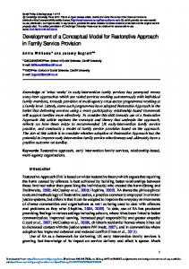
The process has also been applied to several larger case studies, including the mapping of activities from UML 1.4 to UML 2.2, in the 2010 transformation tool competition [21], and the mapping of UML class diagrams, including both single and multiple inheritance, and association classes, to relational database schemas. An example of a constraint from the Cons specification of the migration case study is the mapping of a simple state in UML 1.4 activities to AcceptEventAction instances in UML 2.2: s : SimpleState and s.outgoing.size = 1 and s.outgoing.trigger .size = 1 implies ∃ n : AcceptEventAction · n.name = s.name and n.trigger = s.outgoing.trigger
Figure 3 shows the mapping of a signal-triggered transition from a UML 1.4 SimpleState to a semantically equivalent UML 2.2 diagram with an AcceptEventAction to consume the triggering event.
e[G]
s
s : SimpleState and s.outgoing.size = 1 and s.outgoing.trigger.size = 1
[G]
n
n : AcceptEventAction and n.name = s.name and n.trigger = s.outgoing.trigger
Fig. 3. Mapping of signal-triggered transitions
The transformation design consists of three phases: 1. phase1: establishes the correspondences between each kind of state vertex and activity node. 2. phase2: establishes the correspondences of guards and transitions with opaque expressions and activity edges, assuming the correspondences of states from phase1. 3. phase3: establishes the correspondences of partitions and activity graphs with activity partitions and activities, assuming the correspondences of states from phase1 and transitions from phase2. The mapping of simple states is implemented as an operation toActivity() post: outgoing.size = 1 and outgoing.trigger .size = 1 implies ∃ n : AcceptEventAction · n.name = name and n.trigger = outgoing.trigger
in SimpleState.
6
Related Work
The paper [6] introduces a language, transML, to support the development of model transformations. This however introduces a set of novel notations for re-
quirements, specification and design. We consider that it is preferable to use standardised and familier notations where possible, particularly UML, with which most model transformation developers can be assumed to be already familiar. Other MDD languages and processes could also be used to systematically develop model transformations using the development process described here, for example, executable UML [9].
7
Conclusions
We have defined a development process and specification technique for model transformations, using UML-RSDS. Modularity is based upon the object-oriented modularity of UML models (class diagrams and behaviour models). Model transformation tools generally lack support for semantic analysis. UML-RSDS provides a completeness check on objects created by rules. Other semantic checks, such as the detection of potentially unbounded recursion between rules, would also be beneficial for developers. Proof that metamodel constraints are established or preserved by transformations (syntactic and semantic correctness) is important in maintaining the integrity and correctness of a system. By decomposing transformations into phases, compositional proof that the transformation establishes a required global relationship between the source and target models can be carried out.
Acknowledgement The work presented here was carried out in the EPSRC HoRTMoDA project at King’s College London.
References 1. D. Akehurst, W. Howells, K. McDonald-Maier, Kent Model Transformation Language, Model Transformations in Practice, 2005. 2. D. Akehurst, S. Kent, A relational approach to defining transformations in a metamodel, in Proceedings UML 2002, Springer-Verlag LNCS, vol 2460, SpringerVerlag, 2002. 3. J. Cabot, R. Clariso, E. Guerra, J. De Lara, Verification and Validation of Declarative Model-to-Model Transformations Through Invariants, Journal of Systems and Software, preprint, 2009. 4. J. Cuadrado, J. Molina, Modularisation of model transformations through a phasing mechanism, Software Systems Modelling, Vol. 8, No. 3, pp. 325–345, 2009. 5. H. Ehrig, G. Engels, H-J. Rozenberg (eds), Handbook of Graph Grammars and Computing by Graph Transformation, Volume 2, World Scientific Press, 1999. 6. E. Guerra, J. de Lara, D. Kolovos, R. Paige, O. Marchi dos Santos, transML: A family of languages to model model transformations, MODELS 2010, LNCS vol. 6394, 2010. 7. R. Gronmo, B. Moller-Pedersen, G. K. Olsen, Comparison of Three Model Transformation Languages, proceedings of ECMDA-FA, LLNCS 5562, pp. 2–17, 2009.
8. F. Jouault, I. Kurtev, Transforming Models with ATL, in MoDELS 2005, LNCS Vol. 3844, pp. 128–138, Springer-Verlag, 2006. 9. Kennedy Carter, Executable UML, http://www.kc.com/XUML, 2010. 10. Kermeta, http://www.kermeta.org, 2010. 11. D. Kolovos, R. Paige, F. Polack, The Epsilon Transformation Language, in ICMT 2008, LNCS Vol. 5063, pp. 46–60, Springer-Verlag, 2008. 12. I. Kurtev, K. Van den Berg, F. Joualt, Rule-based modularisation in model transformation languages illustrated with ATL, Proceedings 2006 ACM Symposium on Applied Computing (SAC 06), ACM Press, pp. 1202–1209, 2006. 13. K. Lano, The B Language and Method, Springer-Verlag, 1996. 14. K. Lano, Constraint-Driven Development, Information and Software Technology, 50, 2008, pp. 406–423. 15. K. Lano, A Compositional Semantics of UML-RSDS, SoSyM, vol. 8, no. 1, February 2009, pp. 85–116. 16. K. Lano (ed.), UML 2 Semantics and Applications, Wiley, 2009. 17. K. Lano, S. Kolahdouz-Rahimi, Specification and Verification of Model Transformations using UML-RSDS, IFM 2010. 18. OMG, UML superstructure, version 2.1.1. OMG document formal/2007-02-03, 2007. 19. OMG, Query/View/Transformation Specification, ptc/05-11-01, 2005. 20. OMG, Query/View/Transformation Specification, annex A, 2010. 21. L. Rose, D. Kolovos, R. Paige, F. Polack, Model Migration Case for TTC 2010, Dept. of Computer Science, University of York, 2010. 22. A. Schurr, Specification of graph translators with triple graph grammars, WG ’94, LNCS vol. 903, Springer, 1994, pp. 151–163. 23. P. Stevens, Bidirectional model transformations in QVT, SoSyM vol. 9, no. 1, 2010. 24. D. Varro, A. Pataricza, Automated Formal Verification of Model Transformations, CSDUML 2003 Workshop, 2003.