R++ Home Page, http://w1fa93.hr.att.com/. R++. 3. Dvorak D., Mishra A., Ros J., Singhal A., Weiss,. G. "Using Rules in Object Oriented Designs", accepted as an ...
Pattern-alarm Link PATTERN
ALARM alarm type & device
Receives
THRESHOLD
Has
Generates
Stand-By
Depends-On
DEVICE
Has
Part-Of
STATE
Receives
MESSAGE
Input
Output
Sends
UNIT
Cmd
SNE
PROC
CNI
Creates
ALERT
TICKET
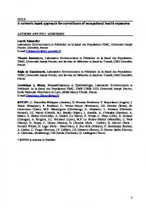
THE KNOWLEDGE BASE OBJECT MODEL
Note : that a Threshold is a function of Device and Alarm type.
2. rule Device::alert_if_standby_oos { Device *stby = standby && State *st = stby->state &&
3.
st->name == "oos" Alarm * mx @ self_msg && (mp->systime timestamp) &&
4.
=> Time current_time = make_time("now");
Crawford J., Dvorak D., Mishra A., Litman D., and Schneider Peter [1996]. Path based rules in Object Oriented Programming, In AAAI-96, Portland Oregon. R++ Home Page, http://w1fa93.hr.att.com/ R++. Dvorak D., Mishra A., Ros J., Singhal A., Weiss, G. "Using Rules in Object Oriented Designs", accepted as an Experience Report for OOPSLA October 1996. Rumbaugh, M. Blaha et al. , "Object Oriented Modeling and Design", Prentice Hall, 1991.
Alert *new_alert = new Alert(this, current_time, "Alert without thresholding.", "Stand-by partner OOS"); new_alert->display_alert();
} The rule can be interpreted as follows: 1. 2. 3. 4. 5.
if the device has a standby “stby”, and the state of the standby is “out-of-service”, then for each alarm message, mx, on “this” device, if the message has not been consumed (i.e., its a new message), then send an alert.
Note that this rule is accessing the state and alarm message information that is accessible from device. This means that, rules in R++ are path based which is different from OPS5 like system where pattern matching is performed on all objects in working memory. 4.
Conclusions
This paper described a model-based reasoning approach for surveillance of the 4ESS-ES elements in the AT&T communication network. We also presented some features of R++ (a rule based extension of C++) to demonstrate how the concept of "path based rules" can be useful in implementing this system. In the future we will investigate how to extend this approach for surveillance of other switching elements in the AT&T communication network. The authors would like to thank the R++ team consisting of James Crawford, Daniel Dvorak, Diane Litman, Anil Mishra and Peter F. Patel-Schneider for their valuable feedback. 5.
Reference 1.
Crawford, J., Dvorak, D., Litman, D., and Mishra, A. (1995), Device Representation and Reasoning with Affective Relations, In IJCAI-95: Int. Joint Conf. on Artificial Intelligence, Montreal, Canada.
4ESS
TSI44 TSI
TSM 0
CLOCK depends-on
depends-on CNTL 0
stand-by
CNTL 1
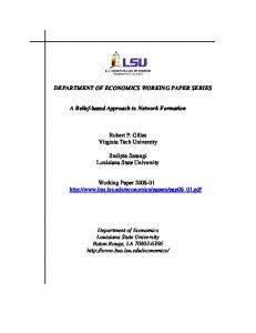
Figure 1 Different relationships in the 4ESS object model
are very important in the diagnostic process of the KB. Figure 1 shows an example of some of these relations in the object model of the 4ESS using OMT. 2.2 Threshold A number of thresholds are defined in the system and for various reasons. A typical threshold object has the attributes type, count1, count2, duration1 and duration2. The type of the threshold specifies the type of alarm that the threshold is defined on, the counts and duration are used to define a window of time over which “count1” and “count2” number of alarm messages are received.
methods are), and are inherited by derived classes. Rules in R++ are path-based, in the sense that rules defined on an object A can only reference (include in their condition) data members of an object B, if and only if B is “accessible” from A. C++ programmers familiar with the use of references (pointers), should interpret accessibility in a similar fashion. For the purpose of illustration consider the following fragment of code: class Device { protected:
2.3 State A device, at any point in time is in some state. A number of states that we have identified are used only internally to the system and do not need to be discussed in detail here. The three basic states that the reader will be interested in however are: OOS (Out-Of-Service), INSVC (In-Service), and DETERMINE (i.e., not known).
String name;
// Device type
int number;
// Device number
monitored State *state; // Affective relations
monitored Device *ipo; // Pointer to containing device. monitored Device *standby // Standby devices for this monitored
2.4 Command //
The ESP sends several types of commands to the switching (4E) element. There are two basic types of commands: (i) commands with a return value expected, and (ii) commands with no return value expected. For the latter type of commands, ESP does not have to wait for any value, it simply sends a command and continues where it left off. 2.5 Alarm An alarm object contains information such as an alarm id, a time stamp indicating the time an alarm was received, the unit, or sub-unit, and some fields containing some details regarding the details of the event that caused the alarm message. When an alarm message is received, information regarding the relevant device, the state (from the event field), and so on are extracted. This information is used to download the appropriate threshold information. The message is then linked to the appropriate device object (if an instance already exists), or a new instance is created and is linked to the alarm object. 2.6 Alerts and Ticket When the alarms on a particular device exceed the maximum threshold then the KB will generate an alert. Also when a device goes out of service KB will first attempt to restore the device. A TICKET will be created if attempts to restore the failed component have failed. A ticket is used to present real work for the technicians. 3. 3.1
The Reasoning Model in the KB R++: Rules and Objects
R++ [2,3] is an extension to the C++ programming language where rules are associated with classes (very much like
// State of the Device
Set_of_p sub_parts; Devices contained in this device
monitored Set_of_p // Transitive closure of ipo.
part_of;
monitored List_of_pself_msg; // Alarm messages for this device. monitored List_of_psub_parts_msg; // Messages on any sub_parts; monitored List_of_p // Messages on dependent devices.
dependent_msg;
... etc.
} The affective relations discussed in the previous section are represented as pointers to other objects (or sets of objects) in the model. The “monitored” keyword in R++ is used to indicate that this data member (attribute) is to be used in the condition of some rule defined on objects of this class. It is important to note here that a rule with a condition on data members of the Device object and the data members of some instance of a State object can be defined since there is a path (an accessibility relation) between Device and State established through the reference of a State in the Device object. In particular, consider the following rule: If a new alarm message is recieved on a device and its standby is in an Out-of-Service state, then send an alert. This rule applies to devices of all types, and so could be defined on the device object and inherited by all derived types of device. Such a rule can be defined in R++ as follows:
A Model Based Reasoning Approach to Network Monitoring Anoop Singhal Gary Weiss Johannes P. Ros AT&T Network & Computing Services {anoop,gweiss,hros}@hrmaple.att.com
Abstract This paper describes a model-based reasoning approach to network monitoring that combines the strengths of object oriented design and rule-based inference. In this approach, the structure of the network equipment is implemented in an object model with diagnostically important relations ("partof", "standby", "depends-on") linking pieces of the equipment. Alarm processing is expressed in data driven rules that monitor the state of the model, and are triggered as each incoming alarm message is attached to the object representing the alarming device. This approach has been used to implement the Knowledge Base of ANSWER-4E, an operations system for monitoring the 4ESS switching system in the AT&T communication network. We have implemented this paradigm in a language that is a rule based extension to C++. We present the merits of this approach and demonstrate how this paradigm can be extended for diagnosis of highly complex systems.
1.
Introduction
This paper describes a hybrid object oriented rule based paradigm that has been used to help automate the surveillance of 4ESS switching elements in the AT&T communication network. The paradigm is based on capturing the affective relations between components of a system in the model. The following are some of the main features of our approach -
-
A network equipment can be naturally broken down into component devices such that the components interact via known relations such as part-of, dependent on. This structure is modeled explicitly using objects. The paths through which alarms propagate to different parts of the equipment are modeled explicitly as inter-object relations.
-
The reasoning for symptom propagation, alarmcorrelation and heuristic alerting is expressed in "path-based" rules that monitor the model, instead of a haphazard collection of situation-action heuristics.
We also describe a rule-based extension to C++ language that enables such an approach to be implemented with ease. The language named R++ [2], bridges the gap between object oriented programming and data-driven computation. This document is organized as follows: Section 2 discusses the object model of the system. In this model, the structure of the network equipment is represented as a semantic network using relations such as "part-of", "is-a", "stand-by", "dependent-on" and so on. These relations [1] are used to perform model-based reasoning in monitoring the network equipment. Section 3 presents a reasoning model for the system. Alarm processing (threshold-based alerting, symptom-propagation, alarm-correlation) is expressed in data driven rules that monitor the state of the model, and are triggered as incoming alarm message is attached to the object representing the alarming device. Finally, section 4 provides conclusions and direction for future work. 2.
The Object Model
In this section we describe a hybrid object-oriented and rulebased design of the expert system. A detailed model of the system using Rumbaugh’s Object Modeling Technique (OMT) is presented in figure 2. 2.1 Device 4ESS Switching equipment is composed of several components. A component can in turn be composed of lower level components until a primitive is reached. The entity device is used to represent a unit of the switching equipment. Some examples of the attributes of a device object are device name and type. There are different “types” of devices, examples of which are "peripheral unit", “clock”, “processor”, etc. There are other relationships among devices, in addition to the “Isa” relation. For example, a device of type TSI contains two devices of type CNTL. In addition to the "Part-of" relationship, there are a number of one-to-many relationships among device objects, such as the “stand-by” and “depends-on” relationships. These relations