A Model-based Signal-In-Space Interface Specification to Support the Design of Galileo Receivers Daniele Gianni, Marco Lisi, Pierluigi De Simone European Space Agency Noordwijk, The Netherlands {firstname.lastname}@esa.int
Andrea D’Ambrogio
Michele Luglio
Dept. of Enterprise Engineering University of Rome TorVergata Rome, Italy
[email protected]
Dept. of Electronic Engineering University of Rome TorVergata Rome, Italy
[email protected]
Abstract—The design and development of Galileo receivers will be a key factor to determine the market approach and penetration. The massive use of the Galileo services will be impacted, as well as the estimated economical return of the Galileo linked activities. In general, GNSS receivers use similar mathematical models for the computation of the global positioning from a standard parameter set. However, receivers design and implementation solutions are often inherently dependent on the specific parameter representations defined in the Signal-In-Space (SIS) interface specifications. In this paper, we introduce Interface Communication Modeling Language (ICML) as a model-based approach for the SIS interface specification to support the engineering of Galileo receivers. We argue that a model-based specification can potentially bring several technical benefits to the design of Galileo receivers, including support for specification communication among stakeholders, reuse and adaptation of existing GPS software and chipsets, and receiver-side multi GNSS interoperability, for example. As a result, a model-based SIS interface specification can contribute to increase the use of the Galileo services by reducing the impact of the technical factors leading to the extra costs. In the paper, we present the overall layout of the ICML language and preliminary applications. In particular, we present a simplified excerpt of a Galileo-like SIS specification and functional schema of GNSS receivers and show how the ICML-based specification can support the design of Galileo receivers. An important caveat: no endorsement is made for the use of the ICML language for the official Galileo SIS interface specification. Galileo, Receiver, Signal-in-Space Interface Specification, Model-based Systems Engineering, Interface Control Document, UML, SysML
I.
INTRODUCTION
The Galileo program is steadily approaching the 2014 milestone in which the system will begin to provide the first early services to the users, namely the Open Service and the Search and Rescue service. Starting from this initial step, the services implementation will gradually improve as the constellation deployment proceeds [1]. Critical to the project success is the support of marketing strategies that promote the use of the Galileo services, possibly generating the estimated economical return in the magnitude of billions of euros. Key issues underlying any marketing strategy concern the Galileo receivers market appealing from cost/performance point of view. As Galileo receivers may require new design and adaptation of existing software (SW) or hardware (HW), as
well as new production chains and higher costs―in particular no recurring costs―are likely to occur with respect to the wellestablished GPS receivers. As a consequence, limitations may be experienced in the market penetration and in the growth velocity of the Galileo receivers’ share in the receiver market. In turn, this may hinder the estimated economical return for the Galileo project. To prevent and counteract this possibility is therefore a critical issue if we aim to achieve the widest success of the Galileo project. Market barriers inherently originate from the following needs: •
Designing new SW and HW solutions for Galileo receivers;
•
Reusing existing SW and HW for GPS receivers;
•
Reconverting existing production chains to the new Galileo-specific SW and HW solutions.
GNSS receivers often use established mathematical models that can determine the global position from a fundamental parameters set, such as satellite orbit and global time. As a consequence, the intrinsic representation of the parameter set is a major factor in the adaptation of the existing design and implementation of SW and HW solutions. In this paper, we propose to support the design of Galileo receivers with the introduction of a model-based approach for the Signal-In-Space (SIS) Interface Specification. The approach is based on the Interface Communication Modeling Language (ICML) [2][3] (Project website: [4]), which can be used to support the design of Galileo receivers in several ways [5], such as: 1.
Reducing ambiguities in the Galileo SIS interface specification;
2.
Enhancing the communication with the involved stakeholders;
3.
Linking the SIS interface specification to the design schemas of GNSS receivers, particularly Galileo ones;
4.
Supporting the model-based design of security solutions for blocking, jamming, and spoofing [6].
The paper is structured as follows. Section II illustrates the key aspects of the Galileo project and the upcoming needs
concerning the receiver design. Section III recalls the main concepts and characteristics of the methods underlying the ICML language. Section IV provides a brief and high level description of the language, with an excerpt of a simplified interface specification. Section V shows briefly how ICMLbased SIS interface specification can support the receiver design in conjunction with receiver functional schemas in SysML. II.
GALILEO PROJECT
Last October, the final two In-Orbit Validation (IOV) satellites were launched into orbit, completing the expected configuration for the Galileo IOV phase. In this phase, preliminary validation tests will be performed and the initial navigation message will be broadcasted down to the Galileo ground segment, for further validation. Shortly after the conclusions of this phase, a series of launches will take place to gradually deploy the remaining 26 satellites that will be forming the Galileo Full Operational Capability (FOC) configuration. Currently, the Galileo Early Open Service (EOS) is expected to be available by the end of 2014 [1]. The EOS will provide ranging capabilities and will enable receiver manufacturers to begin to design and test their technological solutions for Galileo receivers and Galileo overlay services, such as Search-and-Rescue.
as UML (Unified Modeling Language) and SysML (Systems Modeling Language). UML is a formally defined general-purpose graphical language mainly used in the software systems development context [10]. UML is developed and managed by the Object Management Group and is the core standard of the Model Driven Architecture (MDA) effort, which provides a set of standards to shift from code-centric to model-driven software development. By use of a MDA-based approach a software system is built by specifying and executing a set of automated model transformation. SysML is defined as an extension of UML that provides a general-purpose modeling language for systems engineering applications [11]. SysML supports MBSE approaches in the development of complex systems that include hardware, software, information, processes, personnel, and facilities. B. Advantages The main advantages of MBSE approaches can be summarized as follows [9]: •
conformance to standard specifications and availability of development tools;
•
increased level of automation due to the formal specification and execution of model transformations that take as input a model at a given level of abstraction and yield as output a refined model at a lower level of abstraction;
•
better understanding of the system in its operational context;
•
support to simulation activities at different levels of details and different development stages, from concept exploration to dynamic system optimization;
•
support to the coherent extension of standard modeling languages to adapt them to a specific target or domain.
In the meanwhile, the European GNSS Agency has been established and assigned to the governance of the Galileo systems, including activities such as [7]: • • • •
Initiate and monitor the implementation of security procedures and perform system security audits; System infrastructure management, maintenance, improvement, certification and standardization, and service provision; Development and deployment activities of the evolution and future generations of the systems, including procurement activities; Contribute to the exploitation of the systems, to the marketing and promotion of applications and services, including market analysis.
Following, the latest developments in the Galileo project, it becomes increasingly important to support the receiver manufacturers in the design and implementation of Global Navigation Solutions based on the Galileo services. This is necessary to guarantee the use of the Galileo services, particularly in an increasingly crowded GNSS panorama. III.
MODEL-BASED SYSTEMS ENGINEERING
Model-based Systems Engineering (MBSE) is based on the notion that a system is developed by use of a set of system models that evolve throughout the development lifecycle, from abstract models at the early stages down to the operational system [8][9]. A. Main Concepts MBSE approaches are gaining increasing popularity with the widespread adoption of standard modeling languages, such
IV.
ICML LANGUAGE
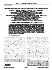
ICML is a modeling language for the representation of interface specification using UML-based technologies. ICML is defined as UML profile and can integrate with system specifications based on compliant technologies. Below, we briefly introduce ICML with a preliminary description of the ICML specification layout and a simplified example of Galileo-like SIS interface specification [12]. Furthermore, we concisely identify the benefits offered by ICML-based specifications, including possible further exploitations. A. Layout of ICML-based Interface Specification ICML-based interface specifications are defined using the layout shown in Figure 1. The specification covers the definition of both the message structure and conversion processes. The message structure consists of five abstraction levels, and describes how the data is structured within the message. The conversion processes describe how the data values are transformed between adjacent levels of the message specification.
The ICML language builds on the UML profiling mechanism and conforms to the ICML metamodel specification presented in [2]. The first prototypal version of the profile has been implemented [13] and can be used within the open source TopCased tool [14]. The prototypal version is available under the GPL v3.0 license from the ICML project website [4]. We applied the profile and developed the below example ICMLbased specification. B. Excerpt of a Galileo-like SIS Interface Specification We considered a simplified part of a Galileo-like OS interface concerning the above-defined level 3 and level 1.
Figure 1 Layout of ICML-based interface specification [5]
Figure 2 shows a detail of the specification for a reduced F/NAV message structure. This structure consists of one Data Frame that in turn consists of F/NAV Subframe 1 and F/NAV Subframe 2.
The message structure is defined at five levels: Data Definition, Binary Coding, Logical Binary Structure, Physical Binary Coding, and Physical Signal, each covering specific aspects of the Signal-In-Space interface specification. For example, the Data Definition level covers the specification of the logical data structure, which includes the data items composing the message information. A data item is either of application or control type. An application data item represents a domain specific concept that conveys the information expected by the message recipient. Differently, a control data item represents a domain independent concept that can support the correctness and integrity verification of the associated application data items. A data item can also be associated to semantic and pragmatic definitions. The former specifies the meaning of the data item and the latter specifies the contextual interpretation for the semantic definition. Analogously, the Binary Coding level covers the specification of the binary coding for each of the data item defined at the above level. For a data item, the binary coding is represented as binary sequence and it includes at least a sequence identifier, the semantic definition, and the pragmatic definitions. Similarly to the above level, the semantic and pragmatic definitions enrich the interface specification, contributing to convey accurate representation of the binary coding. The conversion processes describe the activities to be performed for deriving message values between adjacent levels of the above structural specification. As shown in figure, eight processes should be defined to specify all the conversions between adjacent levels. For example, the DataDefinition2BinaryCoding process defines the activities to be performed for the derivation of the logical binary sequences representing data values. Similarly, the LogicalBinary2PhysicalBinary process defines the activities for the implementation of convolution or encryption algorithms on the logical binary sequence. However, these processes do not always need to be explicitly defined. In particular, if a process is of trivial or standard implementation, a textual note referring to an external document may suffice for the specification purposes.
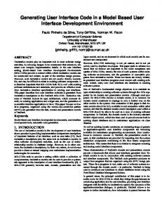
Figure 2 Example ICML-based specification of a F/NAVlike Message Structure at Logical Binary Coding level (3) Figure 3 details the specification of F/NAV-like Page 1. In particular, this page consists of four sequences: Eccentricity and Omegadot—representing application data; Type Field and CRC—representing control data. Each of these sequences are also associated to a number of properties (not displayed by the tool) that describe further details, such as the sequence length, the associated scale factors and offsets, for instance. The specification also links these sequence specifications to the respective sequences at level 4.
Figure 3 Example ICML-based specification of a F/NAVlike Page 1 Structure at Logical Binary Coding level (3) Figure 4 shows some details of an F/NAV-like specification at physical signal level. The diagram defines the
frequency band and the admitted phase ranges. Each phase range is also associated to the binary combination that is represented by the respective signal properties of amplitude (not shown in the diagram), frequency, and phase.
5.
Integration of SIS specifications with receivers design models in SysML, for requirements traceability and reuse of existing GNSS solutions.
The automatic generation of interface specification documents can be an important capability during the lifecycle of a specification. For example, the specification may be updated several times during the interface design, and the textual documentation may need to be produced several times. Using a model-based approach, it is possible to automate the error prone activities related to the document writing as well as other important functions, such as specification versioning. Complex system specifications are often the product of collaborating teams, which may occasionally be geographically distributed. Using a model-based approach, the interface specification can be stored within a version control systems that can be concurrently accessed by team members.
Figure 4 Example ICML-based specification of F/NAVlike at Physical Signal level (0) C. Benefits ICML can bring the above-mentioned MBSE benefits to receiver activities and stakeholders. For example, ICML can: 1.
provide a reference guideline for structuring the specification data and thus facilitating the communication between the Galileo SIS designers and the receivers producers;
2.
ease visual inspection of the specification, for verification purposes;
3.
support syntactical model validation using existing tools;
4.
support for future advance exploitation by means of a machine-readable data format.
In particular, the availability of a machine-readable format is also the base for advanced use cases that can exploit the capabilities of modern computer technologies. D. Advanced Future Use Cases In line with the above-mentioned MBSE model exploitations, we foresee a number of possible exploitation cases: 1.
Automatic generation of the interface specification documents;
2.
Collaborative development of the interface specification;
3.
Automatic completeness and consistency checking of the interface specification;
4.
Integration of SIS specifications with model-driven simulation engineering approaches ([15]) for the simulation of single and multi-GNSS receivers;
The completeness and consistency checking is also a manual activity that demands a high degree of mental attention, and it is consequently highly error prone. Once the specification is available in a machine-readable format, the checking can be easily automated by specifying the verification rules that the interface model must satisfy. Existing technologies support the simulation of single and multi-GNSS receivers. As the SIS specification has a major impact on the internal structure of the receiver, the interface specification is a key input to derive the GNSS simulators as well as to determine the boundary properties of the input signal into the receiver, including the admitted analogue signal and the format of the digital data. Moreover, the model-based interface specification can be integrated with receiver design schema in SysML. This would be important to provide traceability between the interface requirements and the receiver’s functional and physical components. Below, we provide an outline for a preliminary integration between the interface specification and the receiver design. V.
DESIGNING GALILEO RECEIVERS
Model-based interface specification can support the design of Galileo receivers in several ways. For example, the specification can provide a link between Galileo requirements down to the Galileo receiver specifications, as shown in Figure 5.
Figure 5 Links between ICML and SysML specifications
This capability may be useful in several scenarios. In particular, we have identified three scenarios. Scenario 1 consists in the identification of the receiver requirements that are introduced or modified by the Galileo SISOS, with respect to existing GPS receivers. Scenario 2 concerns the linking between the ICML specification and the receiver functional schema to identify how the Galileo receiver will differ from existing GPS solutions. Scenario 3 is a development of Scenario 1 and Scenario 2, in which the physical schema definition and the physical components identification (HW and SW) may further exploit the ICML-based approach for supporting the reuse of existing GPS components.
outgoing arrow, bidirectional arrow, or absence of the arrow, respectively. A port is also considered a type of functional block and must be therefore defined in other diagrams. Similarly to the above described functional block, the port can also be identified by a port name and a port type. Finally, the link is illustrated by the line connecting two or more ports that are congruent with the incoming/outgoing types of the involved ports. The link shows the data flow between the ports and can be associated to a data type, which we have currently omitted in the Figure 6 diagram, for the sake of clarity. However, the data type can also be defined using other SysML diagrams, such as Class Diagram.
Below, we detail Scenario 2, introducing a simplified receiver functional schema in SysML and linking the above ICML example to the schema.
In our study, we have particularly focussed on the RF Front End and on the Data Decoding blocks. The RF Front End is the block that coverts the electromagnetic signal received through the antenna, into a digitalized electric signal. The RF Front End consists of a cascade of filters and amplifiers components, as shown by the electrical schema of Fig. 4.1 in [16]. In our SysML model, we have represented The RF Front End with the Block Definition Diagram (BDD) in Figure 8 and with the IBD in Figure 8. The BDD defines the types of blocks that will be used in the IBD. In particular, this BDD illustrates composition relationships (i.e. black-full diamond and line) between the RF Front End block and a number of block types, according to the shown multiplicities. Specifically, the RF Front End consists of: exactly one Oscillator, one or more Bandpass Filters, one or more Multiplexers, one or more Amplifiers, and one or more Analogic/Digital Converter. Furthermore, each of these block types is also described in terms of several concerns: operations performed by the block, ports for the block communication with the external world, references, values, and properties. For the sake of simplification, we provide only some example properties for some these blocks. For example, The Oscillator block can be described by a frequency which must be expressed in Hz. Currently, we assume that the Oscillator block is ideal. However, inaccuracies and realism properties can still be represented using the SysML modeling capabilities. Similarly, the Bandpass Filter is characterised by a central frequency, a bandwidth, and the frequency of the 3dB cutting edge; each to be expressed in Hz. Other ideal properties can be read directly from the diagram. Real properties, such as dependence on the temperature, etc., can still be represented using SysML modeling capabilities.
A. Example Receiver Functional Schema In this section we illustrate a preliminary SysML representation for a simplified GNSS receiver. However, the below diagrams are meant for exemplification purposes only and are not to be considered fully realistic and detailed for real GNSS receivers. Nevertheless, the SysML hierarchical modeling capabilities can be used to further refine the below model, up to a potentially infinitesimal level of detail. A GNSS receiver functional schema has been derived from [16], and its equivalent SysML Internal Block Diagram (IBD) is shown in Figure 6.
Figure 6 High level Receiver’s IBD―Functional Schema In particular, the IBD illustrates the functional blocks (instances and types) and connections among these blocks that defined the GNSS receiver. The functional blocks are represented by the rectangles, within which the block name and the block type are indicated. The block name indicates the specific instance of a block and is optional. However, if defined, the block name precedes the colon. Differently, the block type is always defined and indicates the inherent characteristics of the block, which must be defined in other diagrams. The block type always follows the colon, even in the absence of the block name. The connections between functional blocks are defined through ports and the link. A port is represented with the tiny square containing the arrow symbol and is implicitly associated to the functional block containing the square. A port can be of several types: input, output, input/output and undefined. Each type is intuitively associated to a different arrow symbol; specifically, the incoming arrow,
Figure 7 RF Front End Block’s BDD
The BDD diagram defines the blocks that can be used in the RF Front End IBD shown in Figure 8. In particular, this diagram represents the connections between the above defined blocks as indicated by the electrical schemas in [16].
Figure 8 RF Front End Block’s IBD Similarly, the Navigation Data Decoder has been derived from the indications available in Chapter 8 of [16]. The Data Decoder is defined by a BDD and an IBD, which are shown in Figure 9 and Figure 10 respectively.
Figure 9 Navigation Data Decoder Block’s BDD In particular, the BDD indicates that the Navigation Data Decoder is composed of four types of blocks: Shift Buffer, Parity Checker, Binary Adder, and Data Item Retriever. The Shift Buffer receives the incoming physical sequence of bits, which is subsequently verified by the Parity Checker. The verified sequence is then processed to retrieve the standard binary format from the SIS-specific logical coding for the data item. This function is guided by the Data Item Retriever, which stores the defined properties of each incoming data items, in the form of physical sequence of bits (level 1). As consequence, the Navigation Data Decoder concerns data defined at several of the above-defined ICML levels. From this description is also possible to sketch the preliminary IBD diagram of Figure 10.
Figure 10 Navigation Data Decoder Block’s IBD
The model can be further extended both in scope and in resolution level. The scope can be enhanced with the introduction of SysML activity, sequence, state and parametric diagrams. The resolution level can also be increased by further detailing each of the above blocks in terms of BDD and IBD. Moreover, SysML parametric diagrams can be used to correlate the properties defined within each of the above blocks. Finally, the completeness of a SysML model lays the foundations for the model execution―i.e. the immediate simulation of the defined model [17], using simulation languages such as Modelica [18]. B. Tracing the SIS onto the Functional Schema Using a model-based approach, it becomes easier to establish links between interface elements and the functional blocks in the receiver schema. Moreover, these links can also be decorated with a number of properties that can be used to further describe the type of the relationship between the interface element and the functional block. The link identification is important to the receiver design in several ways. For example, linking the interface elements to the receiver functional blocks, it becomes easier to identify which functional blocks are affected by each element of the SIS interface. Moreover, the tracing can be transitively extended to the physical schema, enabling the receiver designers to more immediately identify which physical components can be reused or must be replaced in existing GNSS solutions. Below, we exemplify two cases: case 1) the tracing of interface elements on the RF Front End functional schema; and case 2) the tracing of the interface elements on the data decoding functional schema. Similarly to the above diagrams, the below diagrams are meant for exemplification purposes only, to show the ICML potential benefits. Indeed, these diagrams are not to be considered fully realistic and detailed for real GNSS receivers. Moreover, only the above defined ICML level 1 and level 3 elements are considered. Case 1: From Interface Elements to RF Front End Schema. Figure 11 shows the above RF Front End’s BDD in conjunction with ICML level 1 elements (in white). A preliminary number of relationships are drawn in red, including the respective relationship qualifier. This qualifier indicates that the originating block inherently depends on the connected ICML element. The dependency mainly concerns the value of the block’s properties, although refined and extended semantics may be introduced. Case 2: From Interface Elements to Data Decoding Schema. Figure 12 shows the Navigation Data Decoder’s BDD in conjunction with ICML level 3 elements (in white). As in Case 1, the relationships are drawn in red, including a richer set of relationship qualifiers. For example, the qualifier indicates that the originating block uses the data specified in the connected ICML element. Similarly, the qualifier indicates that the originating block takes in input instances of the ICML element. ICML level 4 elements are also relevant to this BDD; however, they are not shown for the sake of conciseness.
research is undergoing to generalize the existing ICML language to more complex types of SIS interfaces. DISCLAIMER No endorsement is made for the use of the ICML language for the official Galileo Signal-In-Space interface specification. ACKNOWLEDGMENT
Figure 11 Linking Level 1 Elements to RF Front End Block Definition
The authors would like to thank the students Serena Annarilli and Carlo Di Bartolomei (University of Rome Tor Vergata) for implementing the first prototypal version of the ICML profile. The authors would also thank Marco Porretta (ESA/ESTEC) for the suggestions on the GNSS example. The ICML project has been partially sponsored by the ESA SOCIS (Summer of Code in Space Initiative), edition 2012. REFERENCES [1] [2]
[3]
[4] [5]
[6]
Figure 12 Linking Level 3 Elements to Navigation Data Decoder Block Definition VI.
CONCLUSIONS
Galileo receivers may face market barriers that are inherently raised by the costs linked with the introduction of new technologies with respect to the existing GPS ones. In this paper, we have advocated that a model-based Signal-In-Space (SIS) interface specification can contribute to mitigate possible extra costs in several ways. For example, the model-based interface specification can ease the communication among stakeholders, promote the reuse and adaptation of existing GPS software and chipsets, and support the implementation of receiver-side multi GNSS interoperability, to mention some. With the objective of supporting model-based interface specifications, we have designed the Interface Communication Modeling Language (ICML), which has also been provided with a UML profile implementation in an open source modeling tool. In the paper, we have also shown a possible excerpt of a model-based specification for a simplified Galileo Open Service interface. Moreover, we have outlined how the model-based specification can integrate with SysML models of GNSS receivers and support the reuse and adaptation of the existing solutions. A preliminary identification of potential exploitations and further benefits is also included. Further
[7] [8] [9]
[10] [11]
[12]
[13]
[14] [15]
[16]
[17]
[18]
M. Lisi, “Galileo Integrated Approach to Services Provision”, Galileo Workshop, ION GNSS 2012, Nashville, TN, US, Sept. 2012. D. Gianni, J. Fuchs, P. De Simone, and M. Lisi, “A Modeling Language to Support the Interoperability of Global Navigation Satellite Systems”, GPS Solutions, Springer Verlag, July, 2012. D. Gianni, A. D’Ambrogio, P. De Simone, M. Lisi, and M. Luglio, “Model-based Interface Specification to Support Systems Integration in Systems of Systems Engineering”, INCOSE International Symposium 2012, Rome, 2012 . ICML Project Home Page: https://sites.google.com/site/icmlmodellinglanguage/ . D. Gianni, J. Fuchs, P. De Simone, and M. Lisi, “A ModelBasedApproach toSignal-in-Space Specifications for Designing GNSS Receivers”, InsideGNSS, January/February, 2011. J. S. Warner, and R.G. Johnston, “GPS Spoofing Countermeasures”, Homeland Security Journal, Dec. 2003. H. Tork, “Status of Galileo”, Galileo Workshop, ION GNSS 2012, Nashville, TN, US, Sept. 2012. A. Kossiakoff, W.N. Sweet, Systems Engineering Principles and Practice. Wiley, New York, NY, (2003). A.W. Wymore, “Model-Based Systems Engineering Methodologies, in Journal of National Council on Systems Engineering 1(1):83-92, 1994. Rumbaugh J, Jacobson I, Booch G (1999) The Unified Modeling Language Reference Manual. Addison Wesley, New York, NY. S. Friedenthal, A. Moore, R. Steiner, A Practical Guide to SysML The Systems Modeling Language. Morgan Kaufman – The OMG Press, Burlington, MA (2011). European GNSS (Galileo) Open Service, Signal In Space Interface Control Document, Issue 1.1. Available from: http://ec.europa.eu/enterprise/policies/satnav/galileo/files/galileo-os-sisicd-issue1-revision1_en.pdf . S. Annarilli, C. Bartolomei, D. Gianni, A. D’Ambrogio, “First Prototypal UML Profile Implementation for the ICML language”, Technical Report, University of Rome TorVergata, October, 2012. TopCased Tool Home Page: http://www.topcased.org/ . A. D’Ambrogio and D. Gianni, 3rd Workshop on Model Driven Approaches for Simulation Engineering, in SCS SpringSim 2013, CA, US. http://www.sel.uniroma2.it/mod4sim13/ . K. Borre, D.M. Akos, N. Bertelsen, P. Rinder, S.H. Jensen, A SoftwareDefined GPS and Galileo Receiver A Single-Frequency Approach Applied and Numerical Harmonic Analysis. Birkhauser, 2006. Johnson, T., Paredis, C., and Burkhart, R., 2008. “Integrating Models and Simulations of Continuous Dynamics into SysML”. In Proceedings of the Modelica Conference, March, 2008. Modelica Association Home Page: http://www.modelica.org/.