bridges the gap between two Technical Domains [5] by ... and Free Choice Petri Nets seems intuitive. ... transformation engine executes the rules to create an.
A Model Driven Approach to Represent Sequence Diagrams as Free Choice Petri Nets Mohamed Ariff Ameedeen, Behzad Bordbar School of Computer Science, University of Birmingham, Birmingham B15 2TT, UK {M.A.Ameedeen, B.Bordbar}@cs.bham.ac.uk
Abstract Model Driven Development (MDD) aims to promote the role of modeling in Software Engineering. Enterprise systems and architectures are often modeled via multiple representations. For example UML models are widely used by the designers to capture various viewpoint of the system; while formal models using languages such as CSP, Z and Petri Nets are suitable for the analysis. Model transformation techniques developed as a part of MDD can be applied to generate one model from another model automatically. This allows benefiting from the tools and techniques developed and used in multiple languages. This paper presents a method of applying MDD model transformation from UML 2.0 Sequence Diagrams to Petri Nets. The paper shows that the model transformation results in Free Choice Petri Nets. As a result, the low complexity of analysis and the synthesis techniques can be applied to the models of enterprise systems which are captured in UML Sequence Diagrams.
1. Introduction In order to reduce the complexity, Enterprise application architectures and methodologies often make use of multiple models for expressing various viewpoints and perspectives of the system. Often multiple software tools are used to handle such modeling languages. For example, to allow analysis of enterprise systems various tools are developed which transform design models to the models which are suitable for the analysis [1-3]. Model Driven Development (MDD) [4] provides the techniques for creating software tools and infrastructure for automated model transformation. In this regard, MDD bridges the gap between two Technical Domains [5] by automated transformation. However, model transformation is a challenging task i.e. UML2Alloy
[3]. In particular, it is crucial to identify suitable modeling frameworks. Our research is motivated by the challenges of analysis and integration of models used in the design of complex Enterprise systems. Petri Nets are one of the most established formalisms for modeling complex behavior. They are widely used in various application domains for analysis and synthesis [6, 7]. In particular, a subset of Petri Nets known as Free Choice Petri Nets [8], in which conflicts and concurrencies does not occur simultaneously, have proven to be a highly suitable choice for the analysis and synthesis. This paper makes two contributions. Firstly, it presents an MDD Model Transformation, from UML2.0 Sequence Diagram to Petri Nets (SD2PN). This allows converting Sequence Diagrams to Petri Nets automatically. Secondly, the paper proves that Petri Nets generated from SD2PN are Free Choice Petri Nets. This allows benefiting from the low complexity mechanism [8] for the analysis of Free Choice Petri Nets to analyze Sequence Diagrams. Moreover, well developed techniques in synthesis of FCPNs can be applied for the integration of Sequence Diagrams. This is particularly important as Sequence Diagrams are often used to express partial behavior and scenarios; synthesis of Sequence Diagram will allow expressing of overall behavior of the system. Although UML 2.0 [9] explains that Sequence Diagrams do not have simultaneous conflict and concurrencies, the equivalence of Sequence Diagrams and Free Choice Petri Nets seems intuitive. However, to the best of our knowledge, this has not been published before. This paper is organized as follows. Section 2 will discuss preliminary information on MDD, Sequence Diagrams and Petri Nets. Section 3 will describe the steps involved in SD2PN model transformation, including an example of applying SD2PN to a Sequence Diagram based on the Man-in-the-Middle security attack model. Section 4 will feature the proof
that shows all Petri Nets generated via SD2PN are Free Choice Petri Nets.
2. Preliminaries This section reviews the preliminary material related to Model Driven Development, Sequence Diagrams and Petri Nets used in the subsequent chapters.
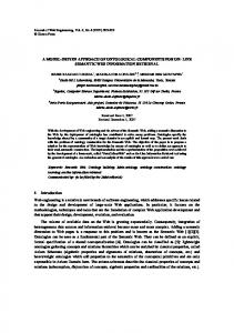
2.1. Model Driven Development Model Driven Development [4] aims to promote the role of modeling in software development. Models in the context of MDD are captured in machine-readable representations, using languages which are widely adopted by software industry [10]. Hence it is possible to communicate such models to various parties and reuse them. This results in lower software production cost and shorter development cycles. In this paper, MDD is further used to develop a method to benefit from advantages of using two representations of a system, Sequence Diagrams and Petri Nets. To allow integration of the presented approach to existing modeling software tools, the standards set by Model Driven Architecture (MDA) [11], a flavor of MDD which is initiated by the Object Management Group (OMG), will be used. Meta Object Facility (MOF) [12] is one of such standards for describing metamodels. Metamodels are themselves models, from which models of the system are instantiated. MOF can be compared to EBNF, which is used for defining programming languages grammars. As a result, MOF is a blueprint from which MOF Compliant metamodels are created. Fig. 1 depicts an outline of MDA and the process of Model Transformation. A number of Transformation Rules are used to define how various elements of one metamodel (source metamodel) are mapped into the elements of another metamodel (destination metamodel). The process of Model Transformation is carried out automatically via the software tools which are commonly referred to as Model Transformation Frameworks [13-15]. A typical Model Transformation Framework requires three inputs: source metamodel, destination metamodel and Transformation Rules. For any instance of the source metamodel, a transformation engine executes the rules to create an instance of the destination metamodel.
Figure 1: Model Driven Development
2.2. Sequence Diagram Sequence Diagrams is UML 2.0 version of Message Sequence Charts [9] and are widely used in Software Engineering [16]. Sequence Diagrams can be used in modeling complex Enterprise Systems as they provide a sequential listing of events and are also able to model parallelism and alternatives. They are also effective in modeling behaviour and concurrency. +coveredBy *
InteractionFragment
+fragment (ordered )
InteractionOperatorKind Alt Opt Break Par
+fragment *
+enclosing Interaction +interaction
0..1
Interaction
1
+interaction
1 +before
+generalOrdering
* +toAfter
Lifeline
+covered
Message
+after 1
+toBefore *
GeneralOrdering
+sendMessage * +message
+operand 1..*
EventOccurrence
InteractionOperand
0..1 1
0..1
1
CombinedFragments +guard InteractionOperator : InteractionOpetratorKind
0..1
InteractionConstraint
+sendEvent 0..1
0..1
0..1
+receiveMessage
+receiveEvent
MessageEnd
Constraint
Figure 2: Metamodel of Sequence Diagram Figure 2 represents a subset of UML 2.0 Sequence Diagrams metamodel used in this paper, comprising of important constructs used for depicting models with complex behavior. The main fragments of the Sequence Diagram are represented by model elements Message and CombinedFragments. The model element Message represents the interaction between the instances of objects in the system while CombinedFragments are high level addition to Sequence Diagrams and consist of Interaction Operators alternative, option, break and parallel. These model elements will be referred to as fragments of Sequence Diagrams throughout this paper. The model element EventOccurrence and GeneralOrdering denotes the sequencing of events in the diagram. EventOccurrence is a specialization of MessageEnd where each message is given a specific
order in reference to the previous and subsequent messages. This paper focuses on the flow of events, therefore the constraints are not considered. However, the constraints could be directly mapped into the transformation resulting in Coloured Petri Nets [17] without changing the rest of our results. Further information on Sequence Diagram could be obtained from the UML Super Specification document [9].
A well-studied subclass of Petri net is called Free Choice Petri Nets [8] in which conflicts and concurrencies cannot occur at the same time. This subclass of Petri Net is predominantly used for effective and efficient analysis in enterprise systems [1]. Moreover, the theory of synthesis of Free Choice Petri Nets is well developed [ ]. 1
1
Petri Net 1..*
1 1
2.3. Petri Nets
1
Marking 1..*
1..*
Place
Petri Nets are a graphical and mathematical modelling language applicable to Enterprise Systems. Petri Nets can be parallel, asynchronous, concurrent, distributed and stochastic as well as being dynamic [6]. Similar to flow-charts, a Petri Net can model the flow of events in a system graphically [18]. Petri nets can be formalized as follows: Definition 1: A Petri Net is a triple N = (S, T, F) where S is a finite set of places and T is a set of transitions where S ∩ T = ∅. F is a relations on S ∪ T where F ∩ (S x S) = F ∩ (T x T) = ∅. A marking of N is a function m:S →{0,1,2,3, …}, where each place s ∈ S is assigned the number of tokens. M0 is used to show the initial marking, the number of tokens in each place at the beginning of execution. Graphical representations of Petri nets depict each place as a circles and each transition as a square. Transitions represent actions and places often model pre-set and post-set for the actions. Suppose two places s1 and s2 with a transition t such that s1 is before t and s2 is after t. This means that s1 is in the pre-set of t and s2 is in the post-set of t; which can be written as s1 ∈ •t and s2 ∈ t•. Similarly, the set of input and output transitions for s1 can be written as •s1 and s1• respectively. The execution of the transition t will remove a token from each place in •t and add a token in each place in t•. The execution of a Petri Net is nondeterministic, which means multiple transitions can be enabled simultaneously and the any of the transitions could fire. Figure 3 depicts the metamodel of Petri Net used in this paper. Referring to Definition 1, S and T are represented by the instances Place and Transition while InputArc and OutputArc represents the relationship F. The instance Marking refers to the function m:S. Every place may have a Mark which represents the number of tokens that belongs to a place. This instance is represented by an integer, i.e. 0, 1, 2 and so on.
Transition
Mark 1
1
1
1
tokens: Integer *
InputArc
*
*
OutputArc
*
Figure 3: Metamodel of Petri Net Definition 2: Baccelli [19] defines Free Choice Petri Nets, as whenever two transitions in the net share an input place, they must not have any other input places. This can also be written as when ⏐p•⏐ > 1, for every t ∈ p•, ⏐•t ⏐= 1. The above definition ensures that in the Petri Net conflict (a place has more than output) and concurrency (a transition has more than one input) are not occurring at the same part of the net. Therefore, it is possible to have both conflict and concurrency within the net, just not simultaneously. There is another definition of FCPN presented in [8] which is slightly weaker than the definition presented above, i.e. if a Petri net satisfied Definition 2 will satisfy definition in [8]. For further information on Free Choice Petri Nets see [8, 19].
3. SD2PN Model Transformation This section describes the process of model transformation from Sequence Diagrams to Petri Nets (SD2PN). This transformation is broken down to three steps to illustrate the stages involved in the process. The steps involved are: Step 1: Decomposing the Sequence Diagrams into fragments. Step 2: Transforming each fragment with its equivalent block of Petri Nets. Step 3: Morphing and Substituting the blocks of Petri Nets to create a Petri Net representation of the original Sequence Diagram.
The steps above are described in the sections 3.1 to 3.3. To illustrate the transformation, an example of applying SD2PN is included in section 3.4.
the model transformation ensures correct wiring of the blocks of Petri net to ensure firing of the transition. s1
3.1. Decomposition of Sequence Diagrams into Fragments The process of decomposition of a Sequence Diagram is carried out on the concrete syntax representation and involves identification of various model elements and their relationships. The metamodel of Figure 2 depicts model elements used in a Sequence Diagram. The term Fragments in this paper refers to messages and CombinedFragments consisting of alternatives, options, breaks and parallels. The GeneralOrdering can be used to identify the causality between the EventOccurrences. In Sequence Diagrams, this ordering is the same as top-down visual ordering. The model transformation SD2PN must not only transform the Fragments into their equivalent Petri net, but also must ensure correct ordering between the EventOccurrence so that the blocks of Petri Nets that are generated conform to same the order as the Sequence Diagram fragments. As is depicted in Figure 2, CombinedFragment may include multiple InteractionFragments or even other CombinedFragments. Consequently, each CombinedFragments has a hierarchical structure. To transfer each CombinedFragment, internal Fragments must be transformed and then integrated into the transformation of the high-level Fragment in the hierarchy.
3.2. SD2PN Model Transformation Rules This section will describe in Step 2 of the model transformation process, which transforms each fragments of Sequence Diagram (from Step 1) with a corresponding block of Petri Net. Message: Page 491 of [9] describes a message as either a call for the execution of an operation or depicting sending and receiving of a signal. The execution of a message, m in a Sequence Diagram is depicted as the firing of a transition, t in the corresponding Petri Net. As depicted in Figure 4, places s1 and s2 model precondition and postconditions for the firing of the transition. These places will be used to create correct causality of events within the sequence diagram. As a further condition to this rule, if m is the first message in the Sequence Diagram, then s1 in the corresponding block of Petri Net must be given a token to ensure firing of t. For other messages,
m
SD2PN Rule 1
t
s2
Figure 4: Applying SD2PN to a Message fragment Alternative: The Interaction Operator alternative specifies that a set of event may occur if a condition is satisfied and another set of event will occur otherwise as shown in page 468 of [9]. To preserve this semantics, this fragment is represented as a block of Petri Net that starts with a place s1 that breaks into two transitions t1 and t2. These two transitions denote the different alternative scenarios in the Sequence Diagrams and will each map into a placeholder block ph1 and ph2 respectively, which represent alt_fragment1 and alt_fragment2. These placeholders will later be substituted with the actual events inside the fragment. They will then map into transitions t1 and t2 to signal the end of the alternative fragments and will terminate at place p2 as shown in Figure 5. This paper is dealing with the flow of events within the sequence diagrams. Hence, data related issues such as the transformation of logical constraints, which can be used on the sequence diagram, are not considered. However, transformation of such constraints would be straightforward, by adding the constraints as preconditions to the firing of transitions t1 and t2 to obtain a Coloured Petri net. In this paper, it is assumed that the firing of t1 and t2 occurs non-deterministically. Alternative with more than two alt_fragments can be explained similarly. s1 t1
alt
t2
Alt_fragment1
SD2PN Rule 2
ph1
ph2
Alt_fragment2
t3
t4 s2
Figure 5: Applying SD2PN to an Alternative fragment Option: Interaction Operator option can be treated similar to the alternative fragment. Therefore, the same block of Petri Net as in Figure 5 is used, with
exception of ph1 and ph2 representing opt_fragment1 and opt_fragment2 instead. Break: Break as described in page 468 of [9] consists of a guard (condition) such that when it is satisfied, the operation breaks (i.e. terminates). This is modeled with the help of two transitions: t1 for the case that the guard fails and t2 for when the guard is satisfied. Transition t1 connects to ph1 that represents break_fragment1, which is the set of event that happens if the break condition is not satisfied while t2 leads to place x which is the terminal node. The placeholder ph1 is then connected to a transition t3 as shown in Figure 6 to mark the termination of the block at s2. s1 t1
break Break _fragment 1
SD2PN Rule 4
t2 X
ph1 t3 s2
Figure 6: Applying SD2PN to a Break fragment Parallel: A parallel operator specifies that two or more sets of event should occur concurrently without any pre-defined set of conditions, see page 468 of [9]. As depicted in Figure 7, the corresponding block of Petri Nets must ensure parallel execution of par_fragment1 and par_fragment2. The fragment start with a place and a transition to ensure correct merging with other fragments. s1 par
t1 Par _fragment 1
SD2PN Rule 5
ph1
ph2
Par _fragment 2
t2 s2
Figure 7: Applying SD2PN to a Parallel fragment After each fragments of the Sequence Diagram are transformed into a corresponding block of Petri Net, it has to be put together to generate a complete Petri Net. This is shown in the next step.
3.3. Morph and Substitute This section will describe Step 3, where every block of Petri Net is put together in the order outlined in the original Sequence Diagram to create a complete Petri Net. There are two techniques that will be used in this section: morph and substitute. These techniques are described in the paragraphs below. Morph is used to join two blocks of Petri Net together. As can be observed from Step 2, every block of Petri Net starts and ends with a single place (even break, where x is a terminal node and does not interact with the rest of the Petri Net). To join two of these blocks together, the end node of the first block is morphed into the start of the second block. An example of this operation could be found in Section 3.4. Substitution is used in cases where there are placeholders. The events that are in the actual fragment will be substituted into the placeholders. This will not offer any problems since immaterial of the number of events in a specific fragment, it always starts and end with a place, therefore a substitution can take place. An example of this scenario can be obtained from Section 3.4. The morph and substitute technique is used until all the blocks of Petri Nets are joined together in the order of the original Sequence Diagram.
3.4. An example of SD2PN application In this section, the SD2PN Model Transformation is explained with the help of an example. As defined in the previous sections, the transformation goes through three steps, and it will all be explained using the example in Figure 8 below. The example in Figure 8(a) is a generic man-in-themiddle attack model adapted from [20, 21]. This is a model of a security breach scenario where an Attacker listens in to the communication between the Requester and the Authenticator. During the transmission of a message from the Requester, the Attacker poses as the Authenticator. This enables the Attacker to duplicate all the ‘secret information’ from the Requester, as can be seen in Figure 8 (a). The Attacker then communicates with the Authenticator, posing as the Requester, and sends the ‘secret information’. The Authenticator validates the ‘secret information’ from the Attacker and provides the ‘session key’ to the Attacker. This creates a security breach and grants unauthorized session access to the Attacker. In this diagram, there are 12 messages and one Interaction Operator of type alternative. This means,
Step 1 of the transformation involves the decomposition of the Sequence Diagram into 13 fragments. These fragments are noted in the diagram using the numbered elliptical figures. Requestor
A ttacker
A uthenticator
the first message with the block that represents the second message as shown in Figure 9 below. The end place from the first block morphs into the beginning of the second block, thus joining the two blocks together.
A uthHelper mis cMsg
mis c Ms g
1
mis c Ms gA t miscReturn miscReturnA t
4
2
morph
3 misc MsgA t
check S ecretInfo
5
checkS ecretInfoA t
6
validate
7
v al alt
authenticatedS ession
9
authenticatedS essionA t
8
[trueGuard] 10
An example of using substitution as shown in Figure 10 below is the block of Petri net representing the alternative fragment and the messages in each alt_fragment represented by the placeholders.
11
noA uthentication noA uthenticationA t
Figure 9: Example of morph technique in SD2PN
[else] 12
13
(a) [ trueGuard]
[else]
authenticatedS es sion
mis c Ms g
validate
1
7 authenticatedS essionA t
mis c Ms gA t
ph 1
ph 2
(subs titution )
noA uthentic ationA t
v al
2
8 9
miscReturn
noA uthentic ation
(substitution )
[trueGuard ]
Figure 10: Example of substitution in SD2PN [else]
3
miscReturnA t 4
checkS ecretInfo 5
authenticatedS ession 10
authenticatedS essionA t 12
noA uthentication 11
noA uthenticationA t 13
checkS ecretInfoA t 6
(b)
Morph and substitution are used repeatedly until all the causal fragments are joined, preserving the order from the original Sequence Diagram, generating the Petri net in Figure 8(b). It could be seen that the Petri Net generated in Figure 8 (b) is a Free Choice Petri Net as. There is only one place p with ⏐p•⏐ > 1 in alternative block, in which for every t ∈ p•, ⏐•t ⏐= 1. In the next section, we will establish that every Petri Net generated through SD2PN is a Free Choice Petri Nets.
Figure 8: Example of applying SD2PN to a generic man-in-the-middle attack model
4. SD2PN Model Transformation Generates Free Choice Petri Nets
Step 2 in SD2PN is to transform each of the 13 fragments into its corresponding block of Petri Nets using the transformation rules outlined in Section 3.2. These blocks of Petri Nets then needs to be joined together to generate a complete Petri Net as shown in Figure 8(b). The numbered elliptical figures refer to the original fragments of Sequence Diagram that they were transferred from. This leads to Step 3, using morph and substitution to join the blocks of Petri Net. Every causal block of Petri Net are joined together using morph as explained in Section 3.3. An example of morph is joining the block of Petri Net representing
To prove that SD2PN results in only Free Choice Petri Nets, we need to formalize the definition of the Petri Net Blocks generated by the transformation. These Petri Net Blocks include a new type of node called placeholders, which are depicted by the dotted squares in Figures 5, 6 and 7. Moreover, it can be seen that every Petri Net Block has a unique input place and output place. Definition 3: A Petri Net Block is a four tuple B = (S, T, P, F) where S is a finite set of places, T is a finite set of transitions, and P is a finite set of placeholders.
F ⊆ ((S ∪ P) × T) ∪ (T × (S ∪ P)) is a set of arcs. In(B), Out(B) ∈ S are unique places such that In(B) has no incoming arcs and Out(B) has no outgoing arcs. They represent the start and end places in the Petri Net Blocks respectively. Petri Net Blocks clearly extends the definition of conventional Petri Nets, since a Petri Net Block where P = ∅ is a Petri Net. The formal definition of morph and substitution as used in the previous sections will be presented in Definitions 4 and 5 below. Definition 4: Suppose B1 = (S1, T1, P1, F1) and B2 = (S2, T2, P2, F2) are two Petri Net Blocks. The morphing of B1 and B2, denoted by B1 ⊗ B2 results in a Petri Net Block B = (S, T, P, F) such that T = T1 ∪ T2, P = P1 ∪ P2, S = (S1 ∪ S2) \ {Out(B1)}, In(B) = In(B1) and Out(B) = Out(B2). F = ((F1 ∪ F2) \ {(x, y) ⏐ y = Out(B1)} ∪ {(x, In(B2) ⏐ (x, Out(B1) ∈ F1} ….. (∗). To explain (∗), notice that the arcs in B are obtained by including all the arcs in F1 ∪ F2 except the arcs leading to output places of B1, Out(B1). All arcs that terminates in Out(B1) must be redirected to In(B2) in order to morph B1 and B2. B
Definition 5: Suppose B1 = (S1, T1, P1, F1) and B2 = (S2, T2, P2, F2) are two Petri Net Blocks. Let p be a placeholder in B2. Substituting the Petri Net Block, B1 into p, denoted by B2[B1/p] results in a Petri Net Block, B = (S, T, P, F), where S = S1 ∪ S2, T = T1 ∪ T2, P = (P1 ∪ P2) \ {p}, In(B) = In(B2), Out(B) = Out(B2) and B
F = (F1 ∪ F2 \ {(x, y) ⏐ x = p or y = p}) ∪ {(x, In(B1)) ⏐ (x, p) ∈ F1} ∪ {(Out(B1), y) ⏐ (p, y) ∈ F1} ..... (∗∗). The equation (∗∗) states that arcs in B can be obtained by removing all arcs to and from p and redirecting them to In(B1) and Out(B2) respectively. The definition of Free Choice Petri Nets from Definition 2 can be extended to Petri Net Blocks. Definition 6: A Free Choice Petri Net Block is a Petri Net Block, B = (S, T, P, F) such that for each q ∈ S ∪ P, if ⏐q•⏐ > 1, the for every t ∈ q•, ⏐•t ⏐= 1. Lemma 1 is a direct result of Definition 6. Lemma 1: A Free Choice Petri Net Block with no placeholders is a Free Choice Petri Net.
Lemma 2: The set of Free Choice Petri Net Blocks are closed under morph and substitution, i.e. if B1 and B2 are Free Choice Petri Net Blocks, then B1 ⊗ B2 and B2[B1 / p] where p is a placeholder in B1, are also Free Choice Petri Net Blocks. B
B
B
Proof: To show that B1 ⊗ B2 = (S, T, P, F) is a Free Choice Petri Net Block, suppose q ∈ S ∪ P such that ⏐q•⏐ > 1, then q is either a place or a placeholder in B1 or B2, since q ≠ Out(B1) because ⏐Out(B1) •⏐= 0. In either case, since both B1 and B2 are Free Choice Petri Net Blocks, then B1 ⊗ B2 is also a Free Choice Petri Net Block since B1 ⊗ B2 does not create a new scenario such that ⏐q•⏐ > 1. To show that B2[B1/p] = (S, T, P, F) is a Free Choice Petri Net, we suppose that p is a placeholder in B1. The process of substitution replaces all arcs into p and redirects them into In(B2) and redirects Out(B2) into the output of p. This does not incur any new situation such that ⏐q•⏐ > 1, because the redirection of arcs is a direct mapping from one node to another. Therefore B2[B1/p] is a Free Choice Petri Net Block. B
B
B
Theorem 1: Every Petri Net generated via SD2PN is a Free Choice Petri Net. Proof: As described in Section 3, the first step of the model transformation decomposes the Sequence Diagrams into fragments. In step 2, each fragment are transformed into Petri Net blocks as depicted in Figures 4 to 6. It is straightforward to see that each of the created block is a Free Choice Petri Net Block as for each ⏐q•⏐ > 1, every t ∈ q•, ⏐•t ⏐= 1. Step 3 involves morph and substitution and by Lemma 2, both morph and substitution produces Free Choice Petri Net Blocks. The transformation stops when all placeholders are substituted and the Free Choice Petri Net Block has no more placeholders. By Lemma 1, a Free Choice Petri Net Block with no placeholders is a Free Choice Petri Net.
5. Related Work Van der Aalst [2] makes use of Petri Nets for the analysis of Workflow Management Models. Using the analytical capabilities of Petri Nets, the Workflow Models are analyzed, i.e. validation, verification, and performance analysis. Vanhatalo et. al. [1] decomposed Business Process Models into blocks of Single Entry Single Exit (SESE) models and analyzed each blocks independently. This technique makes it possible to analyze the liveness and soundness of a
Business Process Model. Moreover, they outlined that the fastest technique used in the analysis of Workflow Models are by transforming them into Free Choice Petri Nets. Delatour and Lamotte [ ] uses Petri Net as a replacement for State Chart Diagrams in UML. This was to provide a more formal semantics for UML diagrams. They also provided a tool, ArgoPN [ ], where the Petri Net is generated while allowing the users to switch back and forth from UML to Petri Nets. All the above approaches aim to provide tools and infrastructure for the automated analysis of models created by the designer. Our work is different from all the above approaches as we adopt a Model Driven approach which allows us better maintenance of the model transformations and their rapid modification. Anastasakis et al [20] describe the challenge of model transformation from UML [9] to Alloy [22] to create UML2Alloy [3], a tool for the analysis of UML models via the Alloy framework. UML2Alloy allows the analysis of static models which are decorated with OCL constraints [23]. Moreover, behavior of the system in UML2Alloy is modeled via Pre / Post conditions with the help of OCL. However, Alloy does not provide the mechanisms required for capturing complex dynamic behavior such as parallelism. Implementing the model transformation presented in this paper will allow us to extend UML2Alloy for better handling of the analysis of Sequence Diagrams. We are currently in process of implementing SD2PN via SiTra [24] to be integrated into UML2Alloy toolset. There are various semantic that are defined for Sequence Diagrams [25-27], offering different ways to formalizing Sequence Diagrams. There are also other interpretation such as Alur [28] who created an analysis method for Message Sequence Charts. He used a top-down visual order method which is also similar to the method adopted by many others i.e. Kuster-Filipe [27] and Muscholl [29]. Kuster-Felipe created a semantic for Sequence Diagrams and outlined a way for Sequence Diagrams to be transformed into Labelled Event Structures to provide a more formal semantics. We have also adopted a similar approach in our research. The model transformation presented in this paper is complex. As a result, it is crucial to prove its correctness i.e. establish that any Sequence Diagram and the corresponding Petri Net created via SD2PN have similar behavior. To achieve this, a common semantics domain is required to compare the behavior of the Sequence Diagram and the Petri Nets. We have developed a proof for the correctness of SD2PN which uses Labelled Event Structure as a common semantics domain. Figure 11 depicts the outline of our approach
in which φ is a semantic map introduced by KusterFilipe [27] and ψ is a semantic map introduced by McMillan [30] used in unfolding of Petri Nets. The proof is exhaustive and long, and due to space limitations, it is not included in this paper. Sequence Diagrams
SD2PN
φ LES
Petri Nets ψ
=
LES
Figure 11: Using LES as a common semantics domain to prove correctness of transformation
6. Conclusion This paper presents a method of applying Model Driven Development techniques to create Petri Net representation of UML2.0 Sequence Diagrams. The model transformation decomposes a Sequence Diagram into fragments and maps them into an extension of conventional Petri Nets called Petri Net blocks. A Petri Net Block may have a placeholder in which another Petri Net Block can be substituted. Moreover, Petri Net Blocks can be combined (morphed) together to create larger Petri Net Blocks. The paper also proves that Free Choice Petri Net Blocks are closed under morph and substitution. As a result, SD2PN transforms Sequence Diagrams into Free Choice Petri Nets. This allows applying lowcomplexity analysis and synthesis techniques using Free Choice Petri Nets into Sequence Diagrams.
8. References [1]
[2]
[3]
J. Vanhatalo, H. Volzer, and F. Leymann, "Faster and More Focussed Control-Flow Analysis for Business Process Models Through SESE Decomposition," in Service Oriented Computing - ICSOC 2007, Fifth International Conference. vol. 4749 Vienna, Austria: Springer, 2007, pp. 43-55. W. M. P. van der Aalst, "The Application of Petri Nets for Workflow Management," The Journal of Circuits, Systems and Computers, vol. 8, pp. 21-66, 1998. B. Bordbar and K. Anastasakis, "UML2Alloy: A tool for lightweight modelling of Discrete Event Systems," in IADIS International Conference in Applied Computing 2005. vol. 1 Algarve, Portugal, 2005, pp. 209-216.
[4] [5] [6] [7] [8] [9] [10] [11] [12] [13] [14] [15]
[16]
[17] [18]
[19]
T. Stahl and M. Volter, Model Driven Software Development; technology engineering management: Wiley, 2006. J. Greenfield and K. Short, Software Factories: Wiley, 2004. T. Murata, "Petri Nets: Properties, Analysis and Applications," Proceedings of the IEEE, vol. 77, pp. 541-580, 1989. E. Badouel and P. Darondeau, "On the synthesis of General Petri Nets," Inria Research Report vol. 3025, 1996. J. Desel and J. Esparza, Free Choice Petri Nets: Cambridge University Press, 1995. UML, "UML Superstructure 2.0, Object Management Group, available at www.omg.org," 2003. UML2.0, "UML 2.0 Superstructure Specification, Final Adopted Specification, available at www.omg.org," 2004. MDA, "Model Driven Architecture, Object Management Group www.omg.org/mda/," 2005. MOF, "Meta Object Facility (MOF) 2.0 Core Specification, Object Management Group, available at www.omg.org,," 2004. ATLAS, "ATLAS, Université de Nantes, http://www.sciences.univ-nantes.fr/lina/atl/," 2005. kermeta, "Triskell Metamodelling Kernel, www.kermeta.org," 2005. D. H. Akehurst, B. Bordbar, M. J. Evans, W. G. J. Howells, and K. D. McDonald-Maier, "SiTra: Simple Transformations in Java," in ACM/IEEE 9TH International Conference on Model Driven Engineering Languages and Systems, 2006, pp. 351-364. J. Campos and J. Merseguer, "On the Integration of UML and Petri Nets in Software Development," in 27th International Conference on Applications and Theory of Petri Nets and Other Models of Concurrency, Turku, Finland, 2006. J. Kurt, Coloured Petri nets (2nd ed.): basic concepts, analysis methods and practical use: volume 1: Springer-Verlag, 1996. J. Butler, R. Hubbly, and W. Melo, "An MOF-based repository for enterprise architecture models," in avaialble at www128.ibm.com/developerworks/rational/library /mar05/melo/index.html, 2005. F. Baccelli, S. Foss, and B. Gaujal, "Free Choice Petri Net: an Algebraic Approach," IEEE Trans. on Automatic Control, 1996.
[20]
[21]
[22] [23] [24] [25]
[26]
[27] [28]
[29] [30]
K. Anastasakis, B. Bordbar, G. Georg, and I. Ray, "UML2Alloy: a Challenging Model Transformation," in ACM/IEEE 10th international confernece on Model Driven Engineering Languages and Systems, 2007, pp. 436-450. G. Georg, I. Ray, K. Anastasakis, B. Bordbar, M. Toahchoodee, and S. H. Houmb3, "An Aspect-Oriented Methodology for Developing Secure Applications," Submitted to Information and Software Technoology, 2008. AlloyAnalyzer, "Alloy Analyzer Website, http://alloy.mit.edu/beta/ [cited February 2005]." 2005. OMG, "UML 2.0 OCL Specification," in Document Id: ptc/03-10-14, OMG Final Adopted Specification ed, 2003. SiTra, "Simple Transformer (SiTra): an MDE tool, www.cs.bham.ac.uk/~bxb/SiTra.html," 2006. X. Li, Z. Liu, and H. Jifeng, "A Formal Semantics of UML Sequence Diagram," in Australian Software Engineering Conference (ASWEC'04), 2004, pp. 168-191. C. Seung Mo, K. Hyung Ho, C. Sung Deok, and B. Doo Hwan, "A semantics of sequence diagrams," Inf. Process. Lett., vol. 84, pp. 125-130. J. Küster-Filipe, "Modelling concurrent interactions," Theor. Comput. Sci., vol. 351, pp. 203-220, 2006. R. Alur, E. Kousha, and Y. Mihalis, "Inference of message sequence charts," in Proceedings of the 22nd international conference on Software engineering Limerick, Ireland: ACM, 2000. A. Muscholl and D. Peled, "Analyzing message sequence charts," in 2nd Workshop on SDL and MSC Grenoble, France, 2000. K. L. McMillan, "A technique of state space search based on unfolding," Form. Methods Syst. Des., vol. 6, pp. 45-65, 1995.