MDD4SOA: Model-Driven Service Orchestration. Philip Mayer1, Andreas Schroeder1, Nora Koch1,2. 1 Institute for Informatics, Ludwig-Maximilians-Universität ...
MDD4SOA: Model-Driven Service Orchestration Philip Mayer1, Andreas Schroeder1, Nora Koch1,2 1
Institute for Informatics, Ludwig-Maximilians-Universität München Oettingenstr. 67, 80538 München, Germany 2 Cirquent GmbH, Arabellastr. 17, 81925 München, Germany [mayer, schroeda, kochn]@pst.ifi.lmu.de
Abstract Service-Oriented Architectures (SOAs) have become an important cornerstone of the development of enterprise-scale software applications. Although a range of domain-specific languages and standards are available for dealing with such architectures, modeldriven approaches starting from models written in an established modelling language like UML and including the ability for model transformation (in particular, for code generation) are still in their infancy. In this paper, we show (1) how our UML-based domain-specific language for working with SOA artefacts, UML4SOA, can be used for modelling service orchestrations, and (2) how to exploit so-designed models in the MDD4SOA approach to generate code in multiple languages, among them BPEL and WSDL, Java, and the formal language Jolie. We use a case study for illustrating this approach. Our main contributions are an easy-to-use, conservative extension to the UML2 for modelling service orchestrations on a high level of abstraction, and a fully automated, model-driven approach for transforming these orchestrations down to code.
1. Introduction Service-Oriented Computing, and in particular Web services have spawned a considerable number of languages and standards for dealing with the various artefacts of SOA systems such as service descriptions, orchestrations, policies, and non-functional properties. Although, as a whole, SOA-based systems promise high flexibility, improved maintainability, and simple re-use of functionality, achieving these properties requires an understanding not only of the individual artefacts of the system, but in particular, of their integration – in other words, the complete picture of the system. Thanks to their graphical nature and high level of abstraction, model-driven approaches are ideal for visualizing the integration of software systems while still maintaining the semantic link between the individual artefacts. Due to these properties, modeldriven approaches are already in use in various
programming paradigms; they are especially prominent in object-oriented and database modelling, where roundtrip engineering is available. However, service-oriented design still falls short of effective and comprehensive domain-specific modelling languages, and code generation tools which exploit the (graphical) models. In an attempt to close this gap, we have introduced MDD4SOA (Model-Driven Development for Service Oriented Architectures; for a first excerpt, see [1]), an integrated UML2-based SOA modelling approach which includes an UML profile (UML4SOA) and model transformation tools for generating code in various target languages. MDD4SOA has been developed as part of the EU project Sensoria [2] and deals with the modelling of structural aspects of services, service orchestrations, policies, and other non-functional properties [3]. In this paper, we introduce the full metamodel and profile of the behavioural aspects of UML4SOA; in particular, of the composition of individual services. This composition has come to be known as service orchestration, and resides at the very heart of serviceoriented computing. In order to support software engineers with intuitive and easy to adopt design and implementation techniques for service orchestrations, we (1) extend the reach of UML2 to the modelling of service composition, and (2) exploit so-designed models for creating executable systems, in particular through code generation. UML is a well-known and mature language for modelling software systems, however it is strenuous right now to model SOA artefacts with UML2, as native support for service and service orchestration concepts is missing. We therefore describe a UML extension for SOA – called the UML4SOA profile – which is a highlevel domain specific language for modelling service orchestrations. One of the main goals of UML4SOA is minimalism and conciseness: service engineers should have to provide only as much information as necessary for the generation of code, and at the same time as little as possible in order to keep diagrams readable.
Regarding the second point, we show the transformation mechanisms of MDD4SOA which convert from UML4SOA models to various executable languages based on MDA principles: Starting from the UML platform independent model (PIM), we transform the model to an intermediate PIM, which, in turn, is converted to the platform-specific models (PSMs) of our target languages. In particular, we target the current Web services standards WS-BPEL (Web Service Business Process Execution Language) [4] and WSDL (Web Service Description Language) [5], the Java language from the object-oriented paradigm [6], and also formal languages which may serve as input to model checkers; in this case, Jolie, which is based on the SOCK process calculus [7]. The main aim is the generation of comprehensible and maintainable code. Our UML profile and our transformations have been implemented as plug-ins for several UML modellers and the Eclipse platform [8]. This paper is structured as follows: We discuss current problems with modelling service orchestration using the UML in section 2, and present our UML2 profile to deal with these problems in section 3. Section 4 then discusses a fully automatic transformation for creating code out of UML2 orchestrations modelled as presented in section 3. We put our work into perspective in section 5, and conclude our findings in section 6.
2. Modelling Orchestration in Plain UML UML2 is accepted as the de facto standard for the modelling of software systems. We select UML for modelling service-oriented software as UML provides an extension mechanism for defining so-called domain specific modelling languages; secondly, there is good tool support for the UML itself and additions defined through the extension mechanism. For modelling the structure of SOAs, UML2 component diagrams and deployment diagrams can be used. UML4SOA includes model elements for these static aspects, namely services, service descriptions and service interfaces. For further details the reader is referred to [3]. More challenging is the task of modelling the behaviour of service-oriented systems, in particular the orchestration of services. Service orchestrations introduce a set of key distinguishing concepts: partner services, message passing among requester and provider of services, long-running transactions, compensation, and events. We select UML2 activity diagrams for the modelling of service orchestrations as we assume that business modellers are most familiar with this kind of dynamic behaviour diagrams. Other workflow languages use similar graphical representations and petri-net like semantics [9].
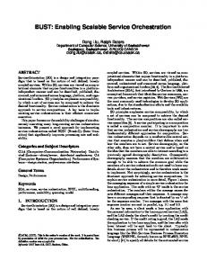
Figure 1: Thesis management modeled with plain UML
As a running example to illustrate our approach, we have chosen an orchestration scenario from the eUniversity domain: we model the management process of a student thesis from the announcement of a thesis topic by a tutor to the final assessment and student notification. This example has been taken from one of the case studies of the Sensoria project [2]. In this orchestration scenario, a tutor provides a thesis topic that is announced to a blackboard regularly read by students. Once a student decides to pick up the topic, it is removed from the blackboard, and the student is registered at the examination office as working on this thesis topic. The student now provides regular updates to the thesis, while the tutor is able to read the status. At the same time, the exercise office may request the cancellation of the thesis if e.g. the deadline for thesis submission elapsed. Upon cancellation of the thesis processing, the thesis topic is freed and re-posted to the blackboard, and the student is informed of the abnormal cancellation. Once the thesis is completed, an assessment of the thesis is requested from the examination office. This request is dispatched by the office to the authorized supervisor of the thesis. Finally, the student is notified once the assessment of the thesis is received. Modelling service orchestrations in plain UML (Figure 1) reveals several important shortcomings, leading to the introduction of (unreadable) technical constructs. In particular, the key distinguishing concepts of service compositions discussed above are missing. For example: • It is not possible to restrict the set of valid callers – as needed e.g. to ensure that only the examination office is able to cancel the thesis – on an UML AcceptCallAction. All restrictions must be implemented manually (area 1). • Temporally enabled event handlers must be disabled using technical constructs. Russel et al. [10] suggest using InterruptibleActivityRegions containing the tasks to disable, and interrupting edges for normal task completion. Although this may be the best achievable solution with plain UML activity diagrams, using these technical constructs makes diagrams harder to understand (areas 2a and 2b). • Similarly, the compensation for an activity is not associated directly with it, but programmed within explicit compensation logic. In addition, programming the compensation logic for more than one compensable activity is a tedious and error prone task [2] (areas 3a and 3b). Due to these shortcomings, modelling service orchestrations with plain UML is a cumbersome task. At the same time, the resulting UML models are difficult to transform to orchestration skeletons for established
service platforms, as the patterns used to handle the issues named above need to be recognized appropriately.
3. Modelling with UML4SOA To overcome the difficulties of modelling services with plain UML, we extend the UML2 with servicespecific model elements. Our UML extension is built on top of the Meta Object Facility (MOF) metamodel [11] and defined as a conservative extension of the UML metamodel. For the new elements of this metamodel, a UML profile is created using the extension mechanisms provided by UML2. The principle followed is that of minimal extension, i.e. to use UML constructs wherever possible and only define new model elements for specific service-oriented features and patterns making diagrams simple, consistent and easy to understand. The resulting UML profile for service-oriented architectures provides model elements for structural and behavioural aspects, business goals, policies and nonfunctional properties of SOAs. In this paper we present the metamodel (section 3.1) and the elements of the service orchestration part of the profile (section 3.2); for a complete overview of the extension the reader is referred to [3]. The orchestration scenario from the eUniversity domain is used to illustrate our approach and compare it to the model built with plain UML.
3.1.
UML4SOA Metamodel
For modelling orchestrations in UML, we add specific service-aware elements for activity diagrams. The metamodel depicted in Figure 2 shows these model elements, their relationships with UML elements and the following relationships among each other: • Orchestrations contain a root scope, which in turn contains all necessary elements for modelling the workflow of the orchestration. • Four specialized actions have been defined for sending and receiving data. • Service interactions may have interaction pins for sending or receiving data. • Compensation edges link orchestration activities to actions or scopes that model the compensation. • Specific compensation actions are used to trigger compensation of scopes or other actions. • Event and exception handlers are used to handle emerging events and abnormal conditions, respectively. Hence, the focus of the UML4SOA metamodel is on service interactions, long running transactions, compensation, event-, and exception handling. This metamodel and the corresponding UML2 profile constitute the basis for model transformations
and code generation development process.
3.2.
defining
a
model-driven
UML Profile for SOA
In order to be able to use the elements of the UML4SOA metamodel in UML2 tools, a UML profile must be specified by means of stereotypes and their relationships to the classes of the UML2 metamodel. The objective is to have a distinct graphical representation and clear semantics for service-oriented concepts. The orchestration part of UML4SOA presented in this paper features constructs for modelling behaviour of SOAs, i.e. stereotypes for service interaction based on the exchange of messages as well as compensation of services. A brief description of the most distinguishing stereotypes is given below. • orchestration: A UML Activity for modelling service orchestrations. • scope: A UML StructuredActivityNode that may have associated event, exception and compensation handlers. • send: A UML CallBehaviourAction that sends a message. Does not block. • receive: A UML AcceptCallAction, receiving a message. Blocks until a message is received. • receive&send: A UML AcceptCallAction/ CallBehaviourAction, denoting a sequential order of receive and send actions. • send&receive: A UML CallBehaviourAction/
AcceptCallAction, denoting a sequential order of send and receive actions. • lnk: A UML Pin that holds a reference to the service involved in the interaction. • snd: A UML Pin that holds a container with data to be sent. • rcv: A UML Pin that holds a container for data to be received. • exception: A UML ActivityEdge to associate exception handlers to actions and scopes. • raise: A UML Action that causes normal execution flow to stop and invokes associated exception handlers. • compensation: A UML ActivityEdge to add compensation handlers to actions and scopes. • compensate: A UML Action that triggers the execution of the compensation defined for a scope or activity. • compensateAll: A UML Action that triggers compensation of the actually compensated scope (i.e. calling compensation on all subscopes in the reverse order of their completion). Can be inserted only in scopes defined for compensation. • event: A UML ActivityEdge to associate event handlers to actions and scopes. Note that we do not directly use the UML metamodel elements for calls and events as well as their defined pins, but instead define our own stereotypes. This is due to the fact that a) the UML elements do not have the required data flow semantics we need, i.e.
Figure 2: UML4SOA Metamodel (UML metaclasses in grey)
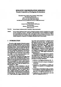
visualized data flow direction is inverse to a service call, b) they have a limited number of input/output pins, and c) they are not always supported by UML tools. Figure 3 shows the example orchestration scenario again, this time modelled with the profile discussed above. The example shows that the control flow complexity is reduced considerably. In particular, all loops introduced for technical reasons become superfluous. Similarly, as UML4SOA offers specialized event edges, the use of exception edges to model completion of activity regions with event handlers become unnecessary. It is important to note that the metamodel introduced above only defines the new elements required for service orchestration and leaves everything else to the UML: the diagram shows how elements from the UML (in this case, actions, structured activity nodes, and branches) have been combined with new elements for service orchestrations (in this case, stereotypes for scopes and service interactions as well as new elements for exception, event- and compensation handling). Also note that initial and final nodes may be omitted in scopes if the control flow is clear. Using the service concepts defined in the
UML4SOA profile reduces the number of edges from 32 to 23 and the number of decision nodes from nine to four, hence allowing the service modeller to focus on implementing service business logic instead of technical constructs. Thus, the value of the produced diagrams is increased for both human reading and automatic processing: the former profits from the conciseness and explicit – but minimalistic – labelling of constructs, while the latter profits from the simpler model structure. The UML2 profile defined above is available as plug-ins several UML modelling tools [8].
4. Model Transformations in MDD4SOA The previous section has shown a profile for modelling SOA orchestrations using UML2 activity diagrams. These models already have great value for communicating the orchestration workflow. However, our MDD4SOA approach also features a set of model transformations which are able to transform the UML4SOA models to platform-specific models (PSMs) of the target languages, from which, in turn, code can be generated.
Figure 3: Thesis management modeled with UML4SOA
The first step in our transformation approach is the conversion of the UML2 PIM models to an intermediate PIM model, which we call the Intermediate Orchestration Model (IOM). This step deals with analyzing the control flow of the UML4SOA models. From the IOM model, we then transform to PSMs, in particular, the Web service standards WS-BPEL and WSDL, the object-oriented language Java, and the formal language Jolie. The complete transformation process is shown in Figure 4.
Figure 4: Transformation Process The transformers are available as plug-ins for the Eclipse platform and are likewise available from [8].
4.1.
Transforming to the Intermediate Orchestration Model (IOM)
The main difficulty in converting UML activity diagrams to PSMs is the structural mismatch between the source and target models. The executable languages we are transforming to do not follow the same graphbased modelling approach as UML; instead, they are based on structured, hierarchical models. One exception is BPEL, where we have two alternatives for creating code: The first alternative employs a graph-based BPEL process, i.e. creates a BPEL process with a flow activity as its root and only structured activity; the control nodes of UML2 – decisions, forks, and loops – are replaced with edge and activity guards. This yields another graph similar to the activity diagram; however, it ignores plenty of BPEL activities dedicated to structuring the orchestration, which would render it more readable. Indeed, with BPEL 2.0 there seems to be a shift towards a more structured approach to the modelling of processes, as more structuring activities have been added. Therefore, we employ the same approach we need for the Java and Jolie languages – in this case, creating a structured BPEL process by converting the UML2 activity constructs to their BPEL equivalents – if/elseif for decisions, flow for forks, and repeatUntil for loops. Identifying Partitions. The main focus of our transformation from the UML2 (PIM) to the IOM (PIM) thus lies on elements which structure control flow. For example, branches and loops are modelled in UML2 using the same elements (decisions/merges); their meaning therefore needs to be inferred from the context, i.e. the number of edges connected to them and their position within the control flow. Thus, the MDD4SOA model transformer employs a rule-based approach to the conversion, which uses a partitioning algorithm to group UML activity diagram nodes for implementation by a certain IOM structured activity. The IOM structured activities are generalized versions of those found in structured programming languages, such as a loop construct, a branching construct, and a construct for parallel execution. There are three types of partitions which need to be identified in the UML source: • Branches. Branching the control flow is modelled in UML with decision and merge nodes. This is converted to an IOM branch construct with multiple guarded paths. • Loops. We assume loops in the control flow to be modelled in UML with merge and decision nodes, with one control path leading from the decision at the end to the merge at the beginning. This is converted to an IOM loop construct with an appropriate guard.
• Parallel flows. Parallel execution is modelled in UML by using fork and join nodes. This is converted to an IOM parallel construct with multiple paths. Besides these induced partitions, we also exploit explicit structuring mechanisms. The UML4SOA profile already introduces the concept of a scope, which greatly eases structuring of activity diagrams and can be found in all of our target languages. The UML profile also allows handlers – exception, compensation, and event – to be attached to a scope. In IOM, they are attached to scopes as well; in this case, the transformation to actual PSMs is more involved. Simple activities, such as receive and send or compensation handling do not pose problems in the transformations and are simply converted to generic equivalents in the IOM model. As an example, the eUniversity scope thesisInProgress contains a loop which encloses one action, namely receiving the message updateStatus from the student. The loop itself has the exit condition thesis.status.completed. The complete scope can therefore be converted to an IOM loop construct with the same guard as the loop condition. Partners of the Orchestration. A service orchestration does not stand alone – it interacts with other services and is itself invoked by clients as a service. Thus, we also need to look at generating descriptions of partner services and the service provided by the orchestration itself, and where to retrieve this information from the input model. Basically, there are two options for describing services along with their operations: One option is to specify services and operations explicitly, and referencing them from within the orchestration. Another option is to infer the services and the roles they play in the process from the orchestration specification itself. This approach is particularly suited for rapid prototyping. Our approach uses the second option, i.e. it is not necessary to specify any services or operations beforehand; they can simply be used as appropriate in the initial UML diagram. The UML-2-IOM transformer then translates this information into a generic interaction model. How a service is used in the orchestration defines its type: • Some services are partners, i.e. the services are external to the orchestration and are called upon to perform some action. • Some services are performed by the orchestration itself, i.e. the orchestration implements the functionality and offers it to partners.
The type is inferred from the use of the orchestration actions send, receive, send&receive and receive&send. There are three possibilities: • If the orchestration only uses send (and send&receive) on a service, the service is clearly external to the orchestration and the orchestration itself is a client of the service. • If the orchestration only uses receive (and receive&send) on a service, the service is offered by the orchestration itself and the partner calls upon the service to perform some action. • Thirdly, the orchestration may use both receive and send on a service. In this case, a flow analysis is employed to find the initial interaction with the service. If the first interaction starts with a receive, we assume that the orchestration itself implements the service and then uses call-backs to send information back to the client. If the first interaction starts with a send, we assume that the service is external to the orchestration and uses call-backs to send information back to the orchestration. The IOM metamodel contains appropriate classes for each case to be converted later to PSMs. In the eUniversity example, all three types are present. For example, the bboard partner is only invoked by the orchestration, but never calls back on its own; it is therefore an instance of the first type, i.e. it is used by the orchestration but defined somewhere else. Another example is the eoffice partner. First, the orchestration sends the student registration to the examination office (thus acting as a client); later on, however, it allows a callback for cancelling the thesis, thus acting as a server. Due to this chain of events, the eoffice partner is an instance of the third type. The MDD4SOA code generator uses a model-2model approach, starting off with an EMF [12] model of the UML2 activity diagram, which can be read from XMI output which many UML modellers are able to produce, and converting to an IOM EMF model. Later on, the IOM EMF model is transformed again to EMF models of the actual target language, for example BPEL and WSDL, which can then be serialized to actual code.
4.2.
Transforming to BPEL
As an example for a complete transformation chain, the following subsections details our code generation approach for converting UML4SOA models to BPEL and WSDL. IOM to BPEL. Although most of the hard work of identifying the UML2 graph structures has already been handled in the UML-2-IOM transformation discussed above, transforming our intermediate object model to BPEL code still requires some work. First of all, the
structured elements identified need to be converted appropriately: • Branches: In BPEL, branching is modelled with an if structured activity which may contain elseif branches for alternatives. • Loops: The equivalent BPEL construct for the original UML2 loops is the RepeatUntil loop, which runs at least once. • Parallel flows: In BPEL, parallel flow is handled through the flow construct, which contains sequences for modelling sequential behaviour inside each of the paths of the original UML2 fork/join group. The scope concept is readily available within BPEL and can be employed as such. Handlers attached to an IOM scope are defined in BPEL within the scopes, thus the actions defined within the handlers in UML need to be moved appropriately.
Figure 5: BPEL code for scope registration
Having handled structural aspects, there are also numerous smaller conversions to be done. As an example, we discuss handling of partner interaction actions. The UML4SOA profile discusses four actions for interactions with other services: • Send. The send action is intended for sending a call to an external partner. It is modelled as a BPEL invoke with only an input variable.
• Receive. The receive action is intended for receiving incoming calls from external partners. It is modelled as a BPEL receive. • Send&Receive. The send-and-receive action is intended for invoking an operation on a partner and receiving a result. It is modelled as a BPEL invoke with both an input and output variable. • Receive&Send. The receive-and-send action first waits for an incoming call and then sends back the value of a predefined variable. It is modelled as a sequence of BPEL receive and reply actions. As pointed out above, conversion of other activities such as compensation invocations and exception raising are simply converted to their BPEL equivalents same as the interactions.
Figure 6: WSDL code for service student
WSDL Generation. As pointed out above, an orchestration – and therefore also a BPEL process – does not stand alone. Therefore, we also need to generate the appropriate WSDL documents from the IOM model. Regarding the four types of interactions discussed above, we can transform them to WSDL as follows: • The orchestration as a client: A WSDL service description needs to be generated which is to be implemented by the external service, and used by the BPEL process for invocation. • The orchestration as a server: A WSDL description needs to be generated which is to be implemented by the BPEL process itself. • The orchestration is both server and client: In this case, we need to generate a service description which contains two port types – one for the service, and one for the client containing the call-backs.
Transformation Examples. As an example for the transformation, Figure 5 shows the BPEL code generated for the scope registration from the example introduced in the previous two sections. Namespace prefixes and some code have been removed for readability. To give an overview of the created WSDL code, Figure 6 shows the relevant code generated for the partner bboard which has one port type and two operations, and is to be implemented by an external service and used by the orchestration.
5. Related Work Several other attempts exist to define UML extensions for service-oriented systems. Most, however, require very detailed UML diagrams from designers, try to force other languages (like BPEL) on top of UML, or do not provide extensions to model vital parts of orchestrations such as compensation handling. The UML 2.0 profile for software services [13] provides an extension for the specification of services addressing structural aspects, but neither behaviour of services nor orchestration of services is addressed in that work. The work of Skogan et al. [14] has a similar focus as our approach, i.e. a model-driven approach for services based on UML models and transformations to executable descriptions of services. The main difficulty in the use of this approach lies in modelling the composition of services. Although they identify patterns to ease the transformations, the approach lacks an appropriate UML profile preventing building models at a high level of abstraction; thus producing overloaded diagrams. The UML extension for service-oriented architectures described by Baresi et al. [15] focuses mainly on modelling such architectures by refining business-oriented architectures. The refinement is based on conceptual models of the platforms involved as architectural styles, formalized by formal graph transformation systems. The extension includes stereotypes for the structural specification of services. However, it does not introduce specific model elements for the orchestration of services. In a recently published article, Ermagan and Krüger [16] extend the UML2 with components for modelling services defining a UML2 profile for rich services. Collaboration and interaction diagrams are used for modelling the behaviour of such components. Neither compensation nor exception handling is explicitly treated in this approach. In 2006, the OMG started an effort to standardize a UML profile and metamodel for services (UPMS). A first draft recently published [17] presents a set of
requirements for such a profile and metamodel, a set of related profiles already defined within the scope of different projects by industrial and academic forums, and a first draft to an integrated solution for heterogeneous architectures. The current version only supports the concepts of service components, service specifications, service interfaces and contracts for services. Another approach to model services is the Service Component Architecture (SCA) [18], which is not based on UML, but is strongly supported by the industry on its way to become an OASIS standard. It focuses on policies and implementation aspects of services. By contrast, Amsden [19] uses plain UML and focuses on the development process of services. A first automated mapping of UML models to BPEL [20] defines a very detailed UML profile that introduces stereotypes for almost all BPEL 1.0 activities – even for those already supported in plain UML, which makes the diagrams drawn with this profile hard to read. Several other approaches have been implemented for the automated transformation from UML to BPEL with the commonality of requiring very detailed UML diagrams from designers. An example is the UML profile described in [21], which defines BPEL-like stereotypes to handle data flow, but does not provide support for compensation. Conversely to these approaches, MDD4SOA focuses on the improvement of the expressive power of UML by defining a small set of stereotypes for modelling SOA orchestrations.
6. Conclusion & Outlook As service-oriented computing continues to gain support in the area of enterprise software development, approaches for handling SOA artefacts and their integration on a high level of abstraction while keeping a semantic link to their implementation become imperative. In this paper, we have argued that modeldriven approaches based on the UML language and employing model transformers to generate code in executable target languages can help to achieve, and keep, an understanding of SOA-based systems. Our main contribution to model-driven software engineering of service-oriented systems is the MDD4SOA approach and tool suite, a concise and intuitive solution to the modelling of services in UML. Our UML4SOA profile provides a small set of model elements that allow the service engineer to produce diagrams which visualize an orchestration of services in a simple fashion. MDD4SOA also includes tools which implement code generation in a model-2-model way and, through several PSMs, address multiple target languages. In all cases, the main aim is the generation of comprehensible and maintainable code.
In particular, the transformation to BPEL discussed in this paper follows the current evolution of BPEL 2.0: using flows to represent the control flow is avoided in favour of more readable structured activity nodes such as conditions and loops. We believe that being able to model service orchestrations in UML and generating code is an important step towards an effective model-driven development of services. We will continue to work on modelling and transformation of other service artefacts, in particular on modelling service interfaces and protocol specifications. Other service-oriented issues will be addressed as well, e.g. the dynamic reconfiguration of SOAs. We also plan to evaluate the advantages of using the UML for visualizing our model transformations. The MDD4SOA tools discussed in this paper are available for download [8].
Acknowledgements
[8] [9]
[10]
[11] [12] [13]
[14]
Thanks go to Alexander Knapp for fruitful discussions on the UML4SOA profile. This research has been partially supported by the EC project SENSORIA “Software Engineering for ServiceOriented Overlay Computers” (6th Framework IST 016004).
[15]
References
[16]
[1]
[2] [3]
[4]
[5] [6] [7]
P. Mayer, A. Schroeder, and N. Koch, "A ModelDriven Approach to Service Orchestration". Intl. Conference on Services Computing (SCC), Honolulu, USA, 2008. M. Wirsing, A. Clark, S. Gilmore et al., "SemanticBased Development of Service-Oriented Systems". FORTE06, Paris, France, pp. 24–45, 2006. N. Koch, P. Mayer, R. Heckel et al., "UML for Service-Oriented Systems (SENSORIA D1.4a)", http://www.pst.ifi.lmu.de/projekte/Sensoria/del_24/ D1.4.a.pdf, [2007]. Last visited: 27.04.2008. OASIS, "Web Services Business Process Execution Language, Version 2.0 (WS-BPEL 2.0)", http://docs.oasis-open.org/wsbpel/2.0/, [2008]. Last visited: 21.01.2008. W3C, "Web Services Description Language, Version 1.1", http://www.w3.org/TR/wsdl, [2007]. Last visited: 21.01.2008. Sun Microsystems, "The Java Programming Language", http://java.sun.com/, [2008]. Last visited: 27.04.2008. F. Montesi, C. Guidi, and G. Zavattaro, "Composing Services with Jolie". ECOWS’07, Halle, Germany, 2007.
[17] [18]
[19] [20]
[21]
"MDD4SOA", http://www.mdd4soa.eu/, [2008]. Last visited: 23.06.2008. W. M. P. v. d. Aalst, "Chapter 10: Three Good reasons for Using a Petri-net-based Workflow Management System", Information and Process Integration in Enterprises: Rethinking Documents, Intl. Series in Engineering and Computer Science, pp. 161–182: Kluwer, 1998. N. Russel, A. H. M. t. Hofstede, W. M. P. v. d. Aalst et al., "Workflow Control Patterns. A Revised View. BPM Center Report BPM-06-22", [2006]. Last visited: 27.04.2008. OMG, "Meta-Object Facility Specification", http://www.omg.org/cgi-bin/doc?formal/2002-04-03, [2002]. Last visited: 27.04.2008. Eclipse Foundation, "EMF: The Eclipse Modeling Framework", http://www.eclipse.org/emf, [2008]. Last visited: 28.04.2008. S. Johnson, "UML 2.0 Profile for Software Services", http://www.ibm.com/developerworks/ rational/library/05/419_soa, [2005]. Last visited: 13.04.2008. D. Skogan, R. Grønmo, and I. Solheim, "Web Service Composition in UML". Eighth IEEE International Enterprise Distributed Object Computing Conference (EDOC'04), pp. 47-57, 2004. L. Baresi, R. Heckel, S. Thöne et al., “Style-Based Modeling and Refinement of Service-Oriented Architectures”, Journal of Software and Systems Modeling (SOSYM), vol. 5, no. 2, pp. 187-2007, 2005. V. Ermagan, and I. Krüger, "A UML2 Profile for Service Modeling". Int. Conf. on Unified Modeling Language, pp. 360-374, 2007. OMG, "UML Profile and Metamodel for Services", http://www.omg.org/docs/ad/07-06-02.pdf, [2007]. Last visited: 10.01.2008. SCA Consortium, "Service Component Architecture (SCA) Policy Framework, Version 1.0", http://www.ibm.com/developerworks/library/specifi cation/ws-sca/. [2007]. Last visited: 27.04.2008. J. Amsden, "Modeling SOA", http://www.ibm.com/ developerworks/rational/library/07/1002_amsden, [2007]. Last visited: 27.04.2008. J. Amsden, T.Gardner, C.Griffin et al., "Draft UML 1.4 Profile for Automated Business Processes with a Mapping to BPEL 1.0", http://www.ibm.com/ developerworks/rational/library/content/04April/310 3/3103_UMLProfileForBusinessProcesses1.1.pdf, [2003]. Last visited: 27.12.2005. K. Mantell, "From UML to BPEL", http://www.ibm.com/developerworks/webservices/li brary/ws-uml2bpel/, [2005]. Last visited: 27.04.2008.