them are also based on the Eclipse platform, e.g., Bioclipse - a workbench for bioinformatics [6]. However, in these approaches the tools are developed manually.
A Model-Driven Workbench for SimulationBased Development of Optical Nanostructures Arif Wider, Martin Schmidt, Frank K¨ uhnlenz, and Joachim Fischer Humboldt-Universit¨ at zu Berlin Unter den Linden 6, D-10099 Berlin, Germany {wider,schmidma,kuehnlenz,fischer}@informatik.hu-berlin.de
Abstract. Model-driven engineering (MDE) advocates the use of domainspecific languages (DSLs) for describing all kinds of systems, but so far DSLs are mostly developed for applications in the software development domain. Because of that, non-IT domain-experts cannot benefit from advances in MDE, e.g., in simulation-based physics, the same experiments have to be described repeatedly in order to use different simulation methods or to verify the results with real-world experiments. This lack of abstraction concerning the experiment description compromises productivity, flexibility, and scientific knowledge transfer. We present a model-driven workbench for developing optical nanostructures, i.e., an integrated set of tools to enable physicists to comfortable describe experiments in their own DSL that abstracts from the way the experiment is performed. We show that existing metamodel-based MDE technologies can be used to automatically generate such tooling from the artifacts that describe a DSL. Keywords: model-driven engineering, domain-specific languages, metamodeling, model transformations
1
Introduction
Model-driven engineering (MDE) is an emerging methodology in software engineering that focuses on the creation and the processing of models. In MDE, models are the primary artifacts and they aim at a high level of abstraction. Models are expressed in modeling languages. There are general-purpose modeling languages (e.g., UML) and domain-specific languages (DSLs). A DSL is a language that is specially tailored to the needs of a certain problem domain. The goal of a DSL is to be particularly expressive in its domain, i.e., common concepts of the domain can be expressed concisely. Therefore a DSL is accessible to domain-experts and allows them to express domain knowledge formally and to process it automatically without requiring programming skills [5]. As a DSL is focused to a specific problem domain, its group of users is smaller than this of a general-purpose language. Therefore, it is not feasible to put as much effort into providing powerful tool support. To help in this respect, there are so-called metatools that can generate DSL-specific tooling – e.g., a rich-featured editor for a DSL – by processing the artifacts that describe the DSL formally.
An integrated set of such DSL-specific tools that makes working with a DSL more comfortable is called a (domain-specific) workbench. Since the release of the Eclipse Modeling Framework 1 (EMF) the Eclipse platform plays an important role concerning MDE tool support. Based on EMF, powerful metatools have evolved, notably, GMF1 for graphical DSLs and Xtext1 for textual DSLs. In this paper, we use Xtext to create a model-driven workbench for the development of optical nanostructures, which is the subject of a cooperation with the physics department of the authors affiliation. Optical nanostructures are structures that are so small that they can be designed to interact with light. Their development aims for certain optical properties, which – in simulation-based physics – are researched using numeric simulation. However, the descriptions of these simulation-based experiments are often tied to a specific simulation method or implementation. Because of that, the same experiments have to be described repeatedly when using different simulation methods or implementations in order to benefit from their individual strengths. Furthermore, experiments have to be described again when the results from simulation are to be verified with real-world experiments. The equivalence of these different experiment descriptions has to be ensured manually. Here, MDE can be applied in order to raise the level of abstraction. Therefore, we develop a DSL for designing photonic crystals – a special kind of optical nanostructures – and for describing experiments with them. This DSL abstracts from the way that an experiment is performed. From this abstract experiment description, the different concrete experiment descriptions can be generated automatically. The corresponding workbench can also mostly be generated. It integrates with different simulation tools so that experimentation is decoupled from a specific simulation method or implementation. Furthermore, equivalence of different experiment descriptions can be ensured automatically. To sum up, we use MDE in two ways: On the one hand, we provide a DSL for creating models that describe experiments on an abstract level and use model transformations to generate concrete experiment descriptions from these abstract experiment models. On the other hand, we use MDE to provide the tooling for our DSL by generating the tool’s program code from models that describe our DSL. The remainder of the paper is structured as follows: In the next section, the domain is explained, i.e., the development of photonic crystals. Section 3 introduces to the technique of metamodel-based language development. In section 4, we apply MDE to the development of optical nanostructures, i.e., we define a DSL and construct the corresponding workbench. Finally, section 5 presents related and future work and concludes the paper.
2
Simulation-Based Development of Photonic Crystals
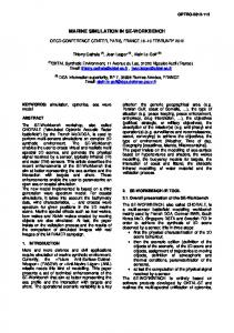
Optical nanostructures are structures that are smaller than the wavelength of visible light. Of particular interest are periodic optical nanostructures, so called photonic crystals (Fig. 1(a)). Photonic crystals are designed to affect the motion of 1
http://www.eclipse.org/modeling/{emf | gmf | tmf }
photons in a similar way that semiconductor crystals affect the motion of electrons. The long-term research goal is to produce photonic components whose features are similar to those of electronic components. In simulation-based development of photonic crystals, typically, the propagation of an electromagnetic pulse is simulated (Fig. 1(b)). As can be seen, the shown structure is a thin membrane with a lattice of holes in it and the simulation shows, that resonances occur where holes were omitted – the so-called cavity – which is the desired behaviour of this structure.
(a) A photonic crystal
(b) Result of simulation shows resonances
Fig. 1. Development of photonic crystals using simulation (figures taken from [1])
There are different simulation methods and different implementations of simulation methods that differ in accuracy as well as in resource consumption. Because of that it is desirable to be able to flexibly choose the method or implementation that fits best for the research question at hand. In our concrete context two different implementations of the finite differences time domain method (FDTD) are mainly used: the commercial tool Lumerical FDTD Solutions 2 and the open-source tool Meep 3 . It can be observed in both tools, that the experiment description is typically divided into four parts: (1) describing the structure itself, i.e., its material and its geometry, (2) defining simulation parameters like resolution and time, (3) defining electromagnetic sources, and (4) monitors that define what information is to be collected during simulation, e.g., a two-dimensional plane in the three-dimensional simulation space. Finally, if the simulation shows satisfying results, these results are verified by producing a real photonic crystal and performing a comparable realworld experiment with it. The specification for this real-world experiment is usually made by hand as the used simulation tools provide only limited export features. Although conceptually the description of an experiment in both tools is very similar, the concrete description differs as in Lumerical experiments are described using either a complex GUI or a tool-specific imperative scripting language whereas in Meep the experiment is described using the functional programming language Lisp. Because of bad interoperability between simulation tools in this area, it is hard to switch between different simulation methods or implementations in 2 3
http://www.lumerical.com/fdtd.php http://ab-initio.mit.edu/wiki/index.php/Meep
order to benefit from their individual strengths. Furthermore, the tool-specific experiment description makes it hard to make sure, that the real-world experiment is equivalent to the simulation-based experiment and hinders knowledge transfer between technologically heterogeneous research groups.
3
Metamodel-Based Language Development
CONCRETE ARTIFACTS
ASPECTS OF A DSL
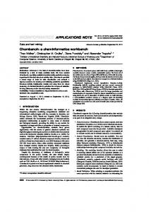
In this paper, we apply a language-driven approach that is based on object-oriented metamodeling [2]. A metamodel is an object-oriented structure similar to a UML class diagram. It is the main artifact to capture domain-specific concepts and the relations between these concepts. In such a metamodel-based context, a domain-specific language comprises a three-tuple of (1) an abstract syntax definition, (2) a set of concrete syntax definitions, and (3) a possibly empty set of execution semantics (Fig. 2). The abstract syntax describes the general language concepts and is defined by a metamodel. All models created using the language have to be instances of that metamodel. Thus, the metamodel defines the set of all possible models that can be created using the language. The concrete syntax defines a graphical or textual notation in which models can be expressed. A textual concrete syntax is usually defined by a context-free grammar that maps constructs of the concrete notation, e.g., certain keywords, to corresponding elements in the metamodel. If the models that were created using the DSL are to be executed, execution semantics have to be defined. This can be done either by providing an interpreter that directly executes models or by providing transformations to either an executable language like Java or to a representation that conforms to a formal execution model like abstract state machines [4]. Domain-specific Language
0..*
1..*
Concrete Syntax
Abstract Syntax
defined by
defined by Grammar or Graphical Specification
Execution Semantics
maps to
Metamodel
defined by works on elements of
Transformation or Interpreter
instance of expressed in terms of
executed with Model
Fig. 2. Aspects of a DSL and concrete artifacts in metamodel-based language development
4
Applying MDE to Nanostructure Development
In this section, we first develop a DSL for describing photonic crystals and for specifying experiments with them. Then, we generate most parts of the corresponding workbench and afterwards modify it to make it perfectly fit to the needs of the domain-experts. We define several execution semantics in order to generate concrete experiment descriptions from the abstract experiment description. Fig. 3 illustrates our approach.
Artifacts describing the DSL
generate
DSL-specific tooling, e.g., a rich editor
create & edit
Model (abstract experiment description)
generate
concrete experiment descriptions
Fig. 3. Applying MDE to the development of optical nanostructures
4.1
Developing the Domain-Specific Language
In order to be able to automatically generate the DSL-specific tooling, we have to describe the DSL formally by providing the artifacts that define the three aspects of a DSL that were presented in the previous section. The design and the syntax of this language is fully determined by the needs and the preferences of the domain-experts. Abstract Syntax For defining the abstract syntax, the domain-specific concepts have to be identified. This is an iterative and communication-intensive process which inherently involves the domain-experts. In interviews and discussions, we had to find out, what mental concepts they use to describe and communicate the design of a photonic crystal and the setup of an experiment. First, as observed in the relevant simulation tools (see sec. 2), the experiment description is divided into four parts: (1) description of the geometry, i.e., the structure by itself, (2) specification of simulation parameters, (3) definition of sources of electromagnetic pulses and their properties, and (4) specification of the data to be collected during simulation (monitors). In the following, we explain the specific concepts of each of these parts. Concerning the description of the geometry of a photonic crystal, we identified the following pattern: The starting point is a cuboid representing the membrane and a lattice of holes in this cuboid. The followig properties of the lattice are to be defined: First, the alignment of the holes needs to be specified, being either rectangular (90 degree) or hexagonal (60 degree). Next, the distance between the holes and their radii have to be defined. Finally, the number of holes is set by specifying a two-dimensional array. Experiments mainly differ in arrangement, shape and size of the holes. Therefore, means to modify the lattice of holes have to be provided. For convenience, we provide means to select and modify a single hole as well as a selection of lines and ranges of holes. The selection is based on the earlier defined array of holes that serves
as a two-dimensional coordinate system in which the origin is located in the middle of the lattice. Each hole – being identified by its coordinates – can be deleted, moved or overwritten by another geometrical object. Furthermore, it is possible to add other geometrical objects and to define different materials to alter the common setup. In the simulation part, parameters of the simulation are specified, e.g., the simulation space can comprise the whole nanostructure or only a selected region. Furthermore the simulation time and the resolution of the simulation are to be defined. The settings made in the simulation part affect the resource consumption of the simulation most. The next part defines the sources of electromagnetic pulses that are propagated within the photonic crystal. It can be specified if the pulse is either a narrowband or a broadband pulse. Additionally, the position and the direction of the source has to be defined. The last part defines monitors, i.e., what data is to be collected during simulation. We identified three types of monitors: a box monitor that collects data in a given three-dimensional space, the frequency-domain field monitor that analyzes data over a given frequency spectrum, and a monitor that focuses on a single point and collects the data over the time. Concrete Syntax After discussions with the domain-experts, we decided for a textual concrete syntax. It is better suited for handling mathematical expressions and there are many tools for the management of text files, e.g., for version control and automatic comparison. In Xtext, the concrete textual syntax is described by a EBNF-based grammar definition. As explained in sec. 3, the concrete syntax is usually described based on the metamodel defining the abstract syntax. However, in our concrete case, we created the concrete textual syntax first with the identified domainconcepts in mind and generated the metamodel afterwards from the grammar as this is the recommended workflow in Xtext. Concrete keywords were defined according to the domain-specific vocabulary of the domain-experts, e.g., the cuboid is called Slab. The following code listing shows a snippet of the geometry part describing the photonic crystal shown in Fig. 1(a). Units are omitted because they are specified globally. Slab { // defining the cuboid representing the membrane material = GaP // defined earlier thickness = 70.0 } Lattice { // defining the lattice of holes lattice_type = hexagonal // 60 degree alignment lattice_size = (19,17) lattice_distance = 209 hole_radius = 0.4 * 200 // modifications to the holes surrounding the cavity overwrite region from (-4,1) to (4,-1) { Cone { radiusGround = 65; radiusTop = 65 } } overwrite region from (-4,0) to (4,0) { Cone { radiusGround = 55; radiusTop = 55 } } move (-4,0) { x_offset = -0.3 } move (4,0) { x_offset = 0.3 }
// the actual cavity delete horizontal line from (-2,0) to (2,0) }
Execution Semantics The DSL is not only about specification and documentation of experiments but also about model execution, i.e., performing the described experiment. In order to abstract from the way an experiment is performed, e.g., using different simulation tools, we implemented model-to-text transformations, that produce input for the different target systems. In our case the target systems are Lumerical FDTD Solutions and Meep (sec. 2). Technically, the transformation is implemented using the Xpand generator framework that integrates well with Xtext. In Xpand, a transformation from a model to text as input for a target system is defined in terms of templates and transformation rules. The main advantage of Xpand is that it works the same metamodel as the concrete syntax. 4.2
Constructing the Workbench
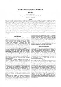
Based on the artifacts that describe the three aspects of our DSL, we use Xtext to generate most parts of the workbench, notably, a rich-featured textual editor for our DSL. The editor’s features include syntax highlighting, auto-completion, validation and other features that usually only can be found in modern IDEs for established programming languages like Java.
Fig. 4. The generated editor for the DSL
Beyond that, we added more features to allow the user to describe experiments more quickly and effectively. We provide templates, e.g., for common modifications of the lattice or the most used parameters for sources and monitors. Furthermore, we allow for user defined values, which can be used for the specification of parameters and can also be used within mathematical expressions. Moreover, these values can be described by external data. This is necessary for using reproducable random values
that slightly vary parts of the experiment – a feature that is often used by the domain experts. Additionaly we adapted the outline view. This view provides an overview of the specified experiment. In this view certain elements of the language are visualized with appropriate graphics. Some of the mentioned enhancements are shown in figure 4, presenting a screenshot of the editor and the corresponding outline view.
5
Conclusions
Related Work There are mature domain-specific workbenches and some of them are also based on the Eclipse platform, e.g., Bioclipse - a workbench for bioinformatics [6]. However, in these approaches the tools are developed manually and much effort had to be put into their development. Because of that, the intended group of users has to be sufficiently large and the problem domain has to be rather broad. By applying a model-driven approach and by using current MDE-technologies that allow for tool-generation, the effort to develop powerful tooling is small enough to develop languages and tools that are only used by small groups and thus, are very much focused on the concrete problem domain of that specific group of users. Results In our cooperation with physicists, we developed a DSL that is specially tailored for describing experiments with photonic crystals. Due to the high expressiveness of this DSL, the experiment description is very concise: in terms of lines of code it is about a factor of three shorter than the corresponding simulation-toolspecific experiment description in Lumerical script or in Meep-specific Lisp code, respectively. At the same time the DSL abstracts from the way the experiments are performed. As a result the domain-experts gain more flexibility in choosing the simulation method and implementation that fits best for the current research question and do not have to describe the same experiment repeatedly in different environments anymore, which was tedious and error-prone. Experiences The process of developing a DSL is a communication-intensive process that involves several iterations with feedback from the domain-experts. The model-driven tool-generation approach matches well to this agile way of language development: After each iteration, there is a working tool-suite that might have some flaws but allows the domain-experts to evaluate it and to decide if their mental concepts have been understood and implemented correctly. Future Work Until now we are only generating input for the target systems and trigger the individual execution. For the future, we are working on reintegrating the results of an experiment back into our workbench. In order to maintain the level of abstraction, that allows for describing the experiment only once, the different results also have to be transformed into a common abstract representation. Furthermore, we are working on integrating a metamodel-based workflow language that allows for defining and executing sets of experiments with different parameters, e.g., automatically iterating over variations of the size of the holes [3]. Beyond that, the integration of a workflow language is the first step towards a multi-view workbench [7] providing several languages. Therefore we are working
on dividing the different parts of our DSL into different languages in order to seperate those parts of the language that are more specific to the problem domain from those parts that are more generic. E.g., the geometry part is tailored to the description of photonic crystals and thus does not allow to describe other optical nanostructures, whereas the way of describing electromagnetic sources is the same for developing different kinds of optical nanostructures. This way, more generic DSLs can be reused together with other very specific geometry DSLs.
Acknowledgement We like to thank Siamak Haschemi for helping us with the development of the workbench and the anonymous reviewers for comments on a preliminary version of this paper. This work is supported by grants from the Deutsche Forschungsgemeinschaft, Graduiertenkolleg METRIK (GRK 1324).
References 1. Barth, M., Kouba, J., Stingl, J., L¨ ochel, B., Benson, O.: Modification of visible spontaneous emission with silicon nitride photonic crystal nanocavities. Optics Express 15(25), 17231–17240 (2007) 2. Clark, A., Sammut, P., Willans, J.: Applied Metamodelling: A Foundation for Language Driven Development, 2nd edn., Ceteva (2008) uhnlenz, F., Fischer, J.: A Language-Centered Approach for Transparent Experimen3. K¨ tation Workflows. In: Proceedings of the 2nd International Conference on Computer Modelling and Simulation (CSSim ’11), Brno, Czech Republic, 5 - 7 September 2011. IEEE (2011), to appear 4. Prinz, A., Eschbach, R., Gotzhein, R.: A Executable Formal Semantics for SDL-2000. In: SAM’00. 2nd Workshop on SDL and MSC, Col de Porte, Grenoble, France. pp. 249–261 (2000) 5. Schmidt, D.: Guest editor’s introduction: Model-driven engineering. Computer 39(2), 25–31 (2006) 6. Spjuth, O., Helmus, T., Willighagen, E., Kuhn, S., Eklund, M., Wagener, J., Murray-Rust, P., Steinbeck, C., Wikberg, J.: Bioclipse: an open source workbench for chemo- and bioinformatics. BMC bioinformatics 8(1), 59 (2007) 7. Wider, A.: Towards Lenses for View Synchronization in Metamodel-Based Domain-Specific Workbenches. In: 3rd Workshop Methodische Entwicklung von Modellierungswerkzeugen (MEMWe ’11) at conference INFORMATIK 2011, Berlin, Germany. GI-Edition of Lecture Notes in Informatics (LNI) (2011), to appear