NISTIR 6746
A Model for the Flow of Design Information in the Open Assembly Design Environment (OpenADE) Steven B. Shooter Walid Keirouz Simon Szykman Steven J. Fenves
NISTIR 6746
A Model for the Flow of Design Information in the Open Assembly Design Environment (OpenADE) Steven B. Shooter Department of Mechanical Engineering Bucknell University Walid T. Keirouz Department of Computer Science Lebanese American University, Byblos Campus Simon Szykman Steven J. Fenves Manufacturing Systems Integration Division National Institute of Standards and Technology
August 2001
U.S. Department of Commerce Donald L. Evans, Secretary National Institute of Standards and Technology Karen H. Brown, Acting Director
A Model for the Flow of Design Information in the Open Assembly Design Environment (OpenADE) *
Steven B. Shooter Department of Mechanical Engineering Bucknell University Lewisburg, PA 17837
[email protected] *
Walid T. Keirouz Department of Computer Science Lebanese American University, Byblos Campus 475 Riverside Dr., #1846 New York, NY 10115
[email protected] +
Simon Szykman and Steven J. Fenves Manufacturing Systems Integration Division National Institute of Standards and Technology 100 Bureau Drive Gaithersburg, MD 20899
[email protected] and
[email protected]
ABSTRACT
This paper describes the OpenADE (Open Assembly Design Environment) project, a framework that is addressing issues relating to the development of information-exchange standards for the next generation of assembly-oriented design tools. The OpenADE architecture itself is based on a design workspace that is shared between a variety of agents. These agents interact with the design workspace using existing or proposed standards-based translators. The two main contributions described in this paper are an information flow model that describes the flow of information in the product development process, and a core representation for product development information. The information flow model classifies design information into various types, organizes these types into information states and levels of abstraction, and identifies the various transformations that operate between the information states. The information flow model has been augmented through the development of a product representation core. Together the information flow model and the representation core provide an infrastructure for semanticallymeaningful information exchanges between software tools used to support various product development activities. Although the information flow model was initially developed as part of a requirements analysis for the OpenADE framework, the end result more generally provides a foundation for interoperability in next-generation product development systems.
*
This work was performed while Professors Shooter and Keirouz were guest researchers at the National Institute of Standards and Technology. + Senior Research Associate, University Professor Emeritus of Civil and Environmental Engineering, Carnegie Mellon University.
Table of Contents Part A: Background and Motivation ........................................................................... 1 1 Introduction......................................................................................................... 1 2 The Agent-Based Architecture............................................................................. 3 2.1 Shared Design Workspace .................................................................................................3 2.2 Design Agents ....................................................................................................................3 2.3 Semantics-Based Data Translators ....................................................................................4
Part B: The Flow of Information in Product Development......................................... 6 3 The Design Information Flow Model................................................................... 6 4 Transformations within a Level of Abstraction .................................................... 8 4.1 4.2 4.3 4.4 4.5 4.6 4.7 4.8 4.9
5 6 7
Customer Needs .................................................................................................................9 Specifications ...................................................................................................................10 Engineering Requirements...............................................................................................10 Family of Solutions..........................................................................................................10 Proposed Artifact .............................................................................................................12 Observed Behavior...........................................................................................................12 Evaluated Behavior ..........................................................................................................12 Evaluated Requirements ..................................................................................................13 General Form of Transformations Within a Level of Abstraction.................................13
Transformations Between Levels of Abstraction................................................ 14 Support of Process Models ................................................................................ 15 Example—Design of a Planetary Gear Transmission......................................... 15 7.1 First Pass Through the Design Information States .........................................................16 7.2 Second Pass Through the Design Information States.....................................................21 7.3 Continued Design of the Gearbox ...................................................................................27
Part C: Representation of Knowledge in Product Development............................... 28 8 Interoperability and Product Development......................................................... 28 9 Next-generation Product Development Tools .................................................... 30 10 Representing the Engineering Context............................................................... 32 10.1 10.2 10.3 10.4
Technical Approach .......................................................................................................32 The Core Representation................................................................................................34 Example: Power Drill Motor .........................................................................................37 Implementation...............................................................................................................39
Part D: Conclusions .................................................................................................... 41 11 Discussion and areas for Future Research .......................................................... 41 Acknowledgments ............................................................................................. 42 References......................................................................................................... 42 Appendix A: The Product Knowledge Representation Core............................... 43
List of Figures Figure 1: The OpenADE Framework ...................................................................................................2 Figure 2: Architecture of OpenADE.....................................................................................................5 Figure 3: Abstract View of Relationship Between Design Information and Design Space ...............7 Figure 4: Design Information Flow Model within a Level of Abstraction .........................................9 Figure 5: Power Drill Schematic..........................................................................................................17 Figure 6: Basic Planetary Gear System ...............................................................................................22 Figure 7: Two Linked Planetary Clusters............................................................................................26 Figure 8. Monolithic Product Development System...........................................................................30 Figure 9. Product Development Using a Heterogeneous Suite of Software Tools. ...........................32 Figure 10. Object Class Hierarchy.......................................................................................................35 Figure 11. Relationship Class Hierarchy. ............................................................................................35
List of Tables Table 1: SIMA Reference Architecture Design Process Model Expressed in the Flow of Design Information Model ....................................................................................................16
PART A: BACKGROUND AND MOTIVATION 1
INTRODUCTION
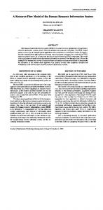
Traditionally, design was undertaken by a small team of designers operating out of a single location. The team captured design information as notes and sketches in logbooks and as design drawings. As a result, team members could easily exchange the relevant design information. The exchange of design information is now much more difficult given the complexity of modern products and design processes. At present, product realization may be a collaborative effort among teams operating at different geographical locations. Design information now comes in many forms and is generated by a wide variety of computer-based tools. However, currently available tools are typically used only during the latter stages of design. They store information that is the outcome of design activities with little regard to capturing the information produced through the development of the design or the processes that generated this information. Furthermore, these tools essentially limit exchange to geometry-related information and provide little support for top-down concept ideation. The shortcomings of these tools provide fertile ground for misunderstandings between participants in a product realization effort. It is anticipated that the next generation of design tools will address these shortcomings and will operate throughout the entire design life cycle of an artifact. The Open Assembly Design Environment (OpenADE) project at the National Institute of Standards and Technology (NIST), an architecture designed to support information exchange and interoperability between design agents, is addressing design information interchange and agent interoperability issues within the context of a collaborative design framework [1, 2]. The main objective for developing the OpenADE architecture is to investigate issues relating to the development of information-exchange standards for the next generation of assemblyoriented design tools. In a collaborative design framework, distributed teams of designers, production engineers, etc., develop products (see Figure 1). These teams use heterogeneous systems, in terms of software and hardware, to generate design information. Furthermore, these teams use a global network to exchange design information and to collaborate on the product development effort. Figure 1 shows the OpenADE Interface that facilitates the communication of design information among design agents. Central to this framework are the communication and storage protocols for design information. The Integrated Design Resource Database stores information on design case studies, component catalog data and other resource information relevant to design. The Design Evolution Database captures all information generated in the design process. This paper deals with the flow of information in the Design Evolution Database. The next section (Section 2) of this paper provides background regarding the architecture and intended role of the OpenADE system. The remainder of this paper is organized into two main parts. Part B describes a model of the flow of design knowledge in the product development process. This model is distinguished from a design process model because information flows among individual design activities independent of their particular sequence. Process models describe or prescribe approaches for conducting the design process. However, individual design teams can follow a multitude or a mixture of design processes. For example, designers may first develop a design alternative without establishing formal specifications or customer needs; these types of information may be formulated later in the process. Part B begins with a description of the design information flow model. After introducing the model, the information transformations within and between levels of abstraction are characterized. The model’s versatility is illustrated by presenting a published design process model expressed in terms of the
1
Immersive CAD
CAD
Virtual Prototyping
Version Revision STEP ….
Case Studies Component Data Other Resource Data ….
Integrated Design Resource Database
Design Evolution Database
Figure 1: The OpenADE Framework
information flow model. The use of this model is then illustrated using as an example the design of a gear transmission for the Black & Decker VP840 cordless drill.1 Future design tools must be able to share design information at much higher levels of abstraction than the current generation of tools does. The next generation of standards must address the issue of sharing design information at these higher levels of abstraction. An exchange of design information between tools is possible only if these tools share semantics. The information exchange will consist of the exchange of data along with an indication of the semantics of the data being exchanged. To enable this information exchange, there is a need to: (1) formalize the semantics of design information, and (2) standardize the exchange of this semantic information. This formalization is already under way. The NIST Design Repository Project [3, 4] is formalizing the semantics of product development information (product structure, product function, etc.). There is a need to extend this semantic model to cover all design information within the life cycle of an artifact. The recognition of the types and levels of design information will lead to techniques and data structures for adequately capturing, storing, and retrieving it. United States industry spends on the order of $109 as a result of poor interoperability between computeraided engineering software tools. While ongoing standards development efforts are attempting to address this problem in today’s tools, next-generation tools such as OpenADE are beginning to capture and manipulate some types of information that are not addressed by existing commercial systems. Thus, if similar interoperability issues are not extended to new kinds of information, the associated with poor interoperability threaten to multiply in the next generation of product development systems. 1
Use of any commercial product or company names in this paper are intended to provide readers with information regarding the implementation of the research described and does not imply recommendation or endorsement by the National Institute of Standards and Technology.
2
Part C of the paper focuses on the development of a core representation for product representation information. The representation is discussed in the general context of supporting interoperability among distributed product development tools. The context of discussion is intentionally left general, as this portion of the work is intended to provide a general foundation for interoperability that extends beyond the scope of the OpenADE system. As OpenADE is designed to be comprised of a set of potentially heterogeneous tools or agents that support different activities, the relevance of the representational infrastructure to the OpenADE framework will be evident. Finally, Part D of the paper discusses conclusions and areas for future work associated with the research described in this paper. 2
THE AGENT-BASED ARCHITECTURE
Elaborating on the OpenADE framework yields the general architecture for the OpenADE system that is shown in Figure 2. This architecture has three major components: 1. A shared design workspace which contains all information relating to the design of an artifact, 2. Agents—independently developed applications—that access and manipulate information in the workspace, and 3. Data translators that allow agents to exchange data with the workspace and with each other using existing or proposed standards. 2.1
Shared Design Workspace
The shared design workspace is viewed as containing all the information relating to a design and acts as the gateway to this design information. This includes descriptions of the designed artifact and of the process leading to the design chosen for the artifact. These descriptions will be at multiple levels of abstraction and are generated during various design stages. The design workspace includes meta-level information, such as a process model, that is used to control the design process itself. It also contains information, such as customer needs and engineering requirements, that acts as input into the process model. The workspace also contains information generated at various design stages. This includes information produced during early stages of design (e.g., a layout model and tolerances based on this model) as well as during detailed design (e.g., assembly planning sequences, and FEA analysis models and results). The shared workspace is accessed by designers using a variety of design tools. A fundamental requirement is that the workspace must support collaboration between designers and allow concurrent access by a variety of design tools. The shared workspace can be implemented as a single database that stores all of the design information. Alternatively, the workspace may consist of multiple databases including databases controlled by individual agents. The workspace integrates these databases through an access layer. In either case, the workspace should be able to retrieve or derive the information requested by an agent. Technologies underlying distributed information systems, such as CORBA and Java Beans, can provide the basic underlying integration and communication infrastructure for implementing the shared design workspace. 2.2
Design Agents
Agents are independent application programs that deal with one or more subdomains of the design domain being dealt with, namely assembly design. These applications may operate on their own or may operate under the supervision of a designer. In contrast to CAD systems whose subsystems are tightly integrated, agents are loosely-coupled. They can run independently of each other and their actions are coordinated via the shared design workspace. Agents access the shared workspace to retrieve design data
3
and store generated information. They have their own representations that they operate on before committing changes to the workspace. Agents are concerned with their own views of the integrated schema. The shared design workspace makes sure that the requested data is available and that data to be stored is consistent with existing data. Agents vary in nature. They range from traditional applications that provide functionality during detailed design (e.g., general-purpose CAD systems) to novel applications that act during preliminary design (e.g., a knowledge-based agent assisting a designer in going from a system specification to function and behavior models). Figure 2 shows an illustrative list of agents that can interact with a shared design workspace. Proceeding from top to bottom first and left to right second, these agents are: •
Process editor—defines a plan for the design process.
•
Process manager—allows a user to keep track of the design process and manage it.
•
Design browser—allows a user to review the descriptions of existing designs: form, function and behavior, design history, etc. [3, 4].
•
Finite Element Analysis agent—uses Finite Element Method techniques to compute physical quantities such as stresses, strains, and temperature distributions. A design environment may contain one or more such specialized FEA agents.
•
Tolerance Analysis agent—performs tolerance analysis or synthesis of a given assembly model. As in the case of FEA agents, a design environment may have several tolerance analysis agents that are specialized to operate during different design stages. An agent may use simplified tolerance models appropriate in preliminary design while another uses sophisticated statistical distribution models.
•
Rapid Prototyping agent—takes a detailed geometric description of an artifact and generates a geometric data set appropriate for rapid prototyping systems.
•
DFM agent—analyzes and critiques the manufacturability of a given artifact design.
•
Knowledge-Based Design agent—assists a designer in going from a system specification to function and behavior models during preliminary design.
•
Assembly Layout agent—assists a designer in laying out the components of an assembly. As in other cases, a design environment may have several such agents that are specialized to given design phases.
•
Traditional CAD agents—allow designers to sketch and dimension parts, etc.
•
Immersive CAD agent—allows a user to interact with an assembly in a virtual reality-based environment [2].
•
Detailed Design agent—allows a user to develop detailed geometry of a component in an assembly.
•
Optimization agent—assists a user in modifying various parameters of an artifact to optimize its design.
2.3
Semantics-Based Data Translators
Data Translators coordinate the exchange of data among the agents and the database. These translators are based on existing standards whenever possible. When such standards are not available, the translators will be formalized to provide input into the standards development effort. The development of these translators assumes that the shared design workspace is based on shared semantics. The various agents that access the shared design workspace operate in their own domains and may have their own
4
Integrated Design DB Process Model
Behavior Model
Function Model
DFM Model & Analysis Results
Features Model
Detailed Geometry
Assembly Planning Model & Analysis Results
Design Rationale
Tolerance Model & Analysis Results
Layout Model
Rapid Prototyping Agent
DFM Agent
Design Context
Kinematic Model & Analysis Results
Tolerance Model & Analysis Results
FEA Model & Analysis Results
Existing/Proposed Standards-Based Translators
Tolerance Agent
Existing/Proposed Standards-Based Translators
FEA Agent
KnowledgeBased Design Agent
Engineering Requirements
Process Manager
Design Browser
Customer Needs
Assembly Layout Agent
Traditional CAD Agents + Pro/Engineer + IDEAS
Immersive CAD
Detailed Design Agent
Optimization Agent
Figure 2: Architecture of OpenADE
representations. Nevertheless, these domains are based on semantics that will be logically part of the semantics of the underlying shared design workspace. As such, the data translators can be developed in two steps. The first step maps the semantics of the agent’s domain onto those of the shared workspace. The second step then uses this semantic mapping to produce a mapping between the agent’s representations and the representations used in the shared design workspace.
5
PART B: THE FLOW OF INFORMATION IN PRODUCT DEVELOPMENT 3
THE DESIGN INFORMATION FLOW MODEL
Design is a complex activity and design processes vary widely from one organization to another reflecting the cultures of design teams. Furthermore, researchers in design theory disagree on the nature of design processes [5]. As a result, the modeling of design information needs to support a wide range of approaches to the design process without imposing undue burden on any such approach. The model for the flow of design information presented here is distinctly different from a design process model where nodes typically represent design actions. Rather, it is an information flow model where nodes represent data flowing between design activities. Design information is simply defined as the data generated or transformed during a product development effort. The proposed information flow model is generic enough that it captures the kinds of information flow that occur during product development irrespective of the particular process model being used. The model contains core entities such as specification, artifact, function, form, geometry, material, and behavior that are commonly described by a multitude of process models. Because of the commonality and the large number of process models, they are not each acknowledged here. The model classifies design information into various types, organizes these types into information states and levels of abstraction, and identifies the various transformations that operate between these information states. The mapping of information flows from one instance of a specific design process onto this flow model will be demonstrated by example in later in this paper. The information flow model assumes that design activities operate in two modes, iterative and layered, that are deeply intertwined. The iterative mode accounts for the various feedback loops that occur as designers seek to satisfy design goals. Furthermore, designers develop design solutions by reasoning about the problem at various levels of abstraction. The layers in the design process correspond to these levels of abstraction. Abstraction simply means the absence of detail. A level of abstraction is a view of a design problem that includes only the issue designers are considering relevant at a given time in the design process. Designers continuously shift between these two modes with minimal effort and accumulate information generated at various levels of abstraction. The relationship between design information and a design space can be thought of as shown in Figure 3. The inner cone represents the design space, which shrinks as the design goes from early stages (a large design space containing many alternatives) to a completed design (a single final design). The outer spiral represents design information. The spiral widens from bottom to top, indicating that the amount of information is increasing as the design approaches completion. Much of the design process is incremental, characterized by the gradually increasing width of the information spiral as it winds around the cone. The design process path drops from one layer of the spiral to another below it when designers need to address a part of the problem at a level of greater detail. The path also jumps up from one layer to another when designers achieve insight into the design problem. The point is that throughout the evolution of the design process that can take many different directions, information continues to flow and accumulate. The challenge is to characterize the flow of design information to facilitate its capture, cataloguing and retrieval so as to support the design process. The effort described here focuses on the information flow rather than the design process. Design activities operate on information, namely the description of the product being designed. The outcome of a design effort is information on what a product is, what it looks like, what it is made of, how it functions, how it should be manufactured, etc. The artifact representing the physical entity being designed is at the center of this information. It is described in terms of three types of information, representing the artifact’s form, function and behavior. These terms have been used widely with slight variations of definition. It is, therefore, useful to define their use in this paper:
6
FINAL DESIGN
Increasing detail
DESIGN INSIGHT
DESIGN REVISION
START DESIGN
Figure 3: Abstract View of Relationship Between Design Information and Design Space
•
The artifact’s form represents its physical characteristics and includes, among others, its geometry and material properties.
•
The artifact’s function represents what the artifact is supposed to do. An artifact satisfies engineering requirements through its function. Function is often used synonymously with intended behavior.
•
The artifact’s behavior represents how the artifact implements its function. Behaviour is governed by engineering principles that are incorporated into a behavior or causal model that can describe or simulate the artifact’s observed or actual behavior based on its form. The behavior model allows designers to explore the satisfaction of function with form.
In the context of this work, the design of an artifact is considered to be a collection of symbols which stand for the artifact’s characteristic properties, be they form, function, or behavior-related. Relationships between these symbols ultimately encode the artifact’s form, function and behavior. Design activities involve actions upon the symbols that describe the artifact in two steps: (1) identifying the symbols and their inter-relationships; and (2) binding values to the symbols. These actions are performed incrementally to add to the artifact’s description until the design is complete. Iteration is accomplished by unbinding values that were bound by some previous activity or by reconsidering the original symbols established. Layering is accomplished by replacing a symbol, or small set of symbols, by a symbol structure (symbols and their relationships) representing the initial symbol(s)’ decomposition at the next level of abstraction (increasing detail). The complex and indirect relationships among an artifact’s form, function, and behavior make design difficult. While designers design an artifact with function in mind, they do so indirectly. Designers cannot specify function directly and have no control over the laws of physics. As a result, they also cannot specify an artifact’s behavior directly. Instead, they try to achieve a desired function by specifying the artifact’s form, which, in turn, drives the artifact’s behavior.
7
The complex array of symbols comprising the description of an artifact is often unwieldy for all but the simplest design problems. Designers therefore use levels of abstraction to control the complexity of the design problem and limit the set of symbols under consideration. The design process involves transformations of symbols within a level of abstraction and transformations of symbols between levels of abstraction. 4
TRANSFORMATIONS WITHIN A LEVEL OF ABSTRACTION
While design theorists differ on the details of the design process, design process models generally agree on the general flow of information from the recognition of customer needs through design generation at various levels of detail with ongoing evaluation and culminating with a final evaluation. It is clear that these design stages are not visited just once, but involve iteration. The information available and generated at each of the stages evolves throughout the design process as additional levels of abstraction having greater amounts of detail are encountered. We first consider each of the stages within a given level of abstraction. The symbols associated with the information at a given level of abstraction represent the design under consideration at that point of time. The symbols may be a subset of the final design or a different set entirely. Figure 4 identifies the states of information within a single abstraction level. These states are differentiated based on whether certain types of information have been created. The branches in the state diagram denote the flow of information between two states. Design activities transform design information and move this information from one state to another. The arcs in the state diagram only indicate the flow of information two states. The text labels attached to some of the arcs indicate design activities that may perform such design information transformations. The actual design activities that achieve the state-to-state transitions and the order in which these transitions occur are determined by the product development process. Not all states must be acted upon at a given level of abstraction. The design information flow model presented in this paper is purely descriptive of how design information is transformed as design progresses. This model can be used to support various activity and process models. However, it is not a process model and does not seek to prescribe any specific process model. A forward walk-through of Figure 4 yields the following. Design information comes into being in the Customer Needs state when customers describe their need for a product. The information reaches the next state, Specifications, when designers and customers formalize the customers’ needs into evaluation criteria. Information in the Engineering Requirements state formalizes the requirements that the artifact must satisfy. To reach the Family of Solutions state, information must include one or more partial descriptions of a proposed design. A description is complete at a given level of abstraction when information reaches the Proposed Artifact state. In the Observed Behavior state, information includes the artifact’s behavior as derived from its description. Answering the question “does the proposed artifact’s behavior match its intended behavior?” transitions information into the Evaluated Behavior state. Designers use this answer to decide, among other things, whether they should further evaluate the proposed artifact, refine the artifact description, or develop an alternate conceptual solution. Design information in the Evaluated Requirements state includes an answer to the question “does the proposed artifact satisfy the engineering requirements?”. Backward-pointing arcs in the state diagram indicate that designers may decide that a given transition has produced an unacceptable result and that they need to backtrack. For example, design information may shift back to the Customer Needs state if the designers decide that the needs cannot be met. It is likely that designers will generate multiple proposed artifacts. The diagram does not include these in the interest of clarity. The various states are described in more detail below.
8
Forward transfer of information through states
Refine needs Customer Needs
Mapping (e.g., QFD) Used downstream for evaluation
Specifications Mapping (e.g., Systematic or Axiomatic Design) Used downstream for evaluation Engineering Requirements Selection Refine requirements
Refine specifications
Family of Solutions Unbound Description
Behavior Model
Intended Behavior
Select new family
Used downstream for evaluation Variable binding(s)
Proposed Artifact Description Simulation/evaluation Observed Behavior Evaluation Rebind variables to new values
Iteration: backtracking to previous states
Evaluated Behavior Evaluation Evaluated Requirements
Figure 4: Design Information Flow Model within a Level of Abstraction
4.1
Customer Needs
Design information reaches the Customer Needs state when customers describe their need(s) for a product in their own languages using both formal and informal terms.
9
4.2
Specifications
Design information moves into the Specifications state when the designers translate the customer needs into specifications expressed in formal technical terms. The specifications relate measurable properties of the artifact to allowable value ranges or limits, and are characterized by metric-and-value pairs. The metric describes the desired property and the value quantifies its acceptable levels. Designers may use several techniques, including Quality Function Deployment [6], to develop the specifications so as to capture the voice of the customer in measurable characteristics that are useful for selecting among solution alternatives. Ideally, designers and customers will communicate throughout this transformation. Designers may also negotiate with customers to revise the customers’ needs should they believe that these needs are not realizable. 4.3
Engineering Requirements
Designers transform the specifications into Engineering Requirements. This transformation introduces the notion of an artifact as the solution to the design problem, meeting the specifications, and reduces this problem to finding an artifact that satisfies the requirements. The requirements state what the artifact should do and look like, etc., to meet the specifications from the designer’s perspective. They express the artifact’s needed functionality as relationships between the artifact’s properties and as constraints that must be satisfied by these properties. The requirements refer to a subset of the artifact’s properties that typically include the artifact’s key characteristics. The transformation of specifications into engineering requirements formalizes the specifications into a structure that supports ideation. This target structure is chosen to support the particular design methodology used by the designers. For example, when Systematic Design [7] is used, designers represent requirements as function blocks characterized by flows of energy, material, or information. These function blocks are later associated with engineering principles to satisfy function. Using an alternative methodology, Axiomatic Design [8], designers create a list of Functional Requirements and use this list to construct a matrix that maps the Functional Requirements to Design Parameters. The information flow model presented here suggests an organization of the engineering requirements into two sets, but does not mandate it. 1 . Function requirements relate to the artifact’s performance. They are characterized by verbs operating and transforming the artifact’s performance characteristics. 2 . Form requirements directly relate to the artifact’s physical aspects. This set includes requirements on size, shape, and material. It also includes assembly requirements needed when the artifact is a component in an assembly or will be attached to fixtures in production processes. The transformation from specifications to engineering requirements may require several iterations. When the mapping is difficult to achieve, the designers may have to revise the specifications and may even have to renegotiate the customer needs with the customer. Furthermore, the requirements will evolve as design progresses. The resulting updates and revisions are documented when deemed significant by designers. 4.4
Family of Solutions
Design information reaches the Family of Solutions state when designers identify a general solution of the design problem at hand. This general solution is an abstraction of a family of artifacts that may meet the engineering requirements and is similar to Gero’s “Design Prototypes” [9]. It describes members of this family of solutions as a collection of symbols that represents an artifact’s characteristic properties. However, the solution family leaves this description incomplete by binding only a subset of the symbols to values; the remaining symbols are left unbound.
10
The family of solutions differs substantially from the traditional “Conceptual Design” (which does not appear in the model). A conceptual design implies a particular level of abstraction. The family of solutions represents a design alternative at any level of abstraction. The family of solutions contains symbols that are not yet bound to a particular instantiation of the artifact. Yet, the family of solutions allows the designers to formulate a behavior model. The relationship between a solution family and its member artifacts is similar to the relation between a class and its instances in object-oriented programming. The class is a template that defines the properties common to its instances in terms of instance variables. The instances customize their behavior by binding the instance variables to values. However, the difference between the formalism presented here and the traditional class-instance view is that what is an artifact (i.e., an instance) at the ith level of abstraction may become a family of solutions (i.e., a class) at the (i+1)th level of abstraction. 2 For example, at one level of abstraction, designers may be considering the family of motors and may bind variables to select a brushless DC motor as the artifact. Having made that choice, at the next level of abstraction (increased detail) designers may be considering now the family of brushless DC motors and need to bind additional variables as part of subsequent refinement steps. The family of solutions defines the properties of its member artifacts and describes the general characteristics of the form, function, and behavior of these members. The solution family has an intended behavior associated with it. As a matter of fact, the solution family is chosen with this intended behavior in mind. This intended behavior is expected to implement the artifact’s needed function or a close approximation to it. The solution family also has a behavior model associated with it. This model is used to derive a member artifact’s observed behavior when the member’s description has been completed. Note that not all members of the solution family are guaranteed to satisfy the engineering requirements. Designers must complete a family member’s description to verify that the member meets all the requirements. As an example of a family of solutions, consider the following design problem. 1. A customer needs to transmit a certain motion between two points. 2. The specifications formalize the problem description and specify success metrics. 3. The engineering requirements describe in detail the motion that must be transmitted (e.g., shapes and durations of motion segments). 4. The designers identify a subset of four-bar linkages as a solution family. 5. The intended behavior describes the desired motion in a manner that can be evaluated against a behavior model. 6 . The behavior model consists of the laws of kinematics that characterize the motion of mechanisms. The description of engineering requirements, identification of a family of solutions, and instantiation of this family of solutions into an artifact occur at a specific level of abstraction. In this case, the designers are trying to solve the delivery of motion problem and are not concerned with second-order effects such as force transmission and flexibility of the mechanism members. The designers have decided to use a four-bar linkage as a family of solutions. At the current level of abstraction, the mechanism remains under-specified as the designers have not specified the lengths of the mechanism members.
2
Note that detail increases as the abstraction level “subscript” does; thus the (i+1)th level of abstraction is of greater detail than the ith level.
11
Designers may use techniques such as brainstorming, intuition, catalog searches, or other structured and unstructured techniques to arrive at a solution family. It is also possible that designers explore multiple solution families simultaneously with each containing the types of information described above. Designers may need to revise or refine the needed engineering requirements when they cannot identify an appropriate family of solutions. This revision may in its turn necessitate a revision of the engineering requirements. 4.5
Proposed Artifact
Design information reaches the Proposed Artifact state when the designers complete the description of the artifact at the current level of abstraction. The designers do so by binding values to the unbound symbols in the description of the solution family, thereby selecting a specific member from the family of solutions. Designers may be able to use the completed description for a quick evaluation of the proposed solution or they may need to proceed to further states for a more detailed analysis using the behavior model specified by the family of solutions. For example, in the case of the delivery of motion problem, the designers specify the lengths of the links in the four-bar linkage. This allows them to observe the artifact’s behavior by simulating the motion delivered by the selected mechanism. 4.6
Observed Behavior
The design information reaches this state when designers derive the artifact’s behavior from its description and the behavior model specified by the solution family. Designers may have several options to derive this observed behavior. They can use a mental simulation, build a physical prototype, or use a general purpose or domain-specific simulation engine, among others. For the delivery of motion example, designers use a mechanism simulation tool to determine the path traced by specific points on the mechanism. At this level of abstraction, a simulation may only take into account the kinematic aspects of the mechanism’s behavior and may not account for other aspects such as force transmission. 4.7
Evaluated Behavior
Design information moves into the Evaluated Behavior state after the designers evaluate the artifact’s behavior. They do so by comparing the artifact’s intended and observed behaviors and classifying any discrepancies between the two as a variation in intended behavior or as an unintended behavior. This classification is based on two criteria: (1) how closely the artifact’s observed behavior matches its intended one; and (2) whether the discrepancy reflects a phenomenon of a different nature than the one anticipated by the designers. The evaluation effectively answers the question, “does the artifact do what it is supposed to do?” and can lead to one of the following three courses of action: 1. The behavior discrepancy is within acceptable bounds and is classified as a variation in intended behavior. Designers decide that the discrepancy does not warrant a further revision of the proposed artifact at the current level of abstraction. The discrepancy itself is noted and may lead to the development of tolerances at the appropriate level of abstraction. 2. The behavior discrepancy is outside acceptable bounds. However, designers assess that they are still dealing with the same phenomenon and classify the discrepancy as a variation. In this case, designers have a choice. They may decide that the current solution family remains promising and that the proposed artifact can be improved. The designers then modify the proposed artifact by binding the solution family’s unbound properties to a new set of values. Designers may use an optimization approach to determine the changes needed. Alternatively, designers may decide that a further investigation of the solution family is unwarranted and select a new solution family.
12
This backtracking may itself result in revising the engineering requirements before the artifact’s design is refined further. 3 . The discrepancy is substantial enough that designers assess that they are dealing with a phenomenon whose nature they did not anticipate; they need to use different terms when describing the intended and observed behaviors. As such, the behavior discrepancy is not simply out of bounds, but rather out of set, and is classified as an unintended behavior. This unintended behavior may lead designers to revise the description of the intended behavior in the current family of solutions, select another family of solutions, or backtrack further to revise the engineering requirements. Alternatively, the unintended behavior may be carried forward to the evaluated requirements for analysis. For the delivery of motion example, the designers can choose to optimize the lengths of the links to match more closely the desired motion., or they may instead decide that the current four-bar linkage is not promising and start with a new set of link lengths. An unintended behavior can appear in the delivery of motion example when subsequent dynamic simulation detects undesirable vibrations in the bars at the operating frequency. The designers must then reconsider their linkage configuration or shape to minimize the vibrations. They may also have to reconsider their approach and explore alternative mechanisms. 4.8
Evaluated Requirements
The design information reaches the Evaluated Requirements state after the designers evaluate whether the artifact satisfies the engineering requirements and meets the specifications at the current level of abstraction. This evaluation takes into account any of the unintended behaviors of the proposed artifact and can lead to one of several courses of action. 1. The proposed artifact meets all requirements and specifications as derived from customer needs. As such, the designers decide that the design is complete at the current level of abstraction. 2. The proposed artifact satisfies the engineering requirements at the current level of abstraction, but not all the specifications. The designers refine the requirements to a more detailed level of abstraction and then refine the design to meet the new set of requirements. 3. The proposed artifact does not satisfy the requirements at the current level of abstraction. The designers must then iterate to consider alternate artifacts, alternate families of solutions, or reconsider the customer needs, specifications or engineering requirements. It is also likely that multiple alternatives would be compared at this point. There would be an evaluation of the degree of satisfaction of the requirements among the alternatives. In performing this evaluation, it is important that each of the alternatives be compared at the same level of abstraction. Otherwise, the evaluation can be invalid. Revisiting the transmission of motion problem, designers have determined the link lengths in a mechanism so it traces the proper trajectory. At the next level of abstraction, a more detailed behavior model that considers the transmission of forces and the dynamic response of the linkage in addition to the transmission of motion may be used. 4.9
General Form of Transformations Within a Level of Abstraction
All of the transformations of design information within a level of abstraction illustrated above typically extend the design by binding values to existing unbound symbols, creating new unbound symbols to be
13
bound in subsequent transformations, or both. In addition to this generic transformation, there are two other useful transformation forms. An Alternative generation or Branchout transformation occurs when a deliberate decision is made to create multiple alternatives. Typically, it occurs in considering multiple Families of Solutions for the same Engineering Requirements or multiple Proposed Artifacts for the same Family, but in principle can occur at every state transition (e.g., alternate specifications, alternate evaluations, etc.). All alternatives start with the same symbols, bound and unbound, representing the common starting state, but then each alternative is pursued by binding different values to the unbound symbols and creating different new unbound symbols. A Mapping transformation occurs when a design state description consisting of a set of unbound and bound symbols, or several such descriptions, is reformulated into an equivalent description using a new set of symbols (equivalent in the sense of representing the same state of the same design at the same level of abstraction). One use of such mapping occurs when alternatives resulting from the branchout transformation described above are compared and reconciled and one alternative is accepted, but possibly modified by symbols from other alternatives. A second use of mapping occurs when the designers decide that a given problem is too difficult to solve at the given level of abstraction. They map the problem description into a reformulated one, making it more tractable, and attempt to solve the reformulated alternate problem. If that solution succeeds, its results are mapped back into the appropriate state of the original problem. 5
TRANSFORMATIONS BETWEEN LEVELS OF ABSTRACTION
The previous section discussed transformations of the design information within a level of abstraction. Designers also transform design information by navigating between levels of abstraction [10]. As stated previously, a Proposed Artifact at the ith level of abstraction may become a Family of Solutions at the (i+1)th level of abstraction. More generally, any symbol, or small set of symbols, at one level of abstraction may be replaced by a symbol structure (a set of symbols and their relationships) that represents the initial symbol(s)’ decomposition at the next lower level of abstraction. Three major types of transformations between levels of abstraction can be identified. After designers solve a design problem by identifying an artifact that meets the requirements at a given level of abstraction, a Refinement transformation occurs when the designers expand the problem’s description by incorporating additional detail, thereby leading to a new abstraction level containing a greater amount of detail. Sequences of successive Refinements may traverse essentially all the states discussed in the previous section at increasing levels of detail, producing the spiral of design information discussed above. Consecutive turns of the spiral are denoted in the design process literature by terms such as conceptual design, preliminary design, final (detailed) design and design documentation. A second type of transformation, which may be termed Exploratory Descent is invoked when designers encounter an impasse: a design state can not be reached or some symbols cannot be bound at the current level of abstraction without deeper exploration. The designers have to descend through one or more levels of abstraction until enough detail has been explored to be able to bind symbols that caused the impasse. The third type of transformation between levels of abstraction may be termed Ascent. Its effect is identical to the Mapping transformation discussed above, in that it produces a new set of symbols, but in this case the new symbols at a given level of abstraction are reformulated from symbols or states at a greater level of detail. Thus, when Exploratory Descent reaches a solution, one or more Ascent transformations convey the results back to the level where the impasse occurred. Ascent transformations also occur in design situations following the successive design refinement scenario. For example, if the
14
global cost constraint is specified at the highest, most abstract level of the artifact only, designers frequently have to ascend to aggregate component costs from more detailed, lower levels of abstraction. Levels of abstraction in the flow of design information model provide a formalism that is needed to develop computational tools for manipulating design information. This formalism is achieved without placing undue burden on designers, as the designers always control the granularity of the model. They choose the levels of abstraction by selecting the symbols to expand when moving from level to level. They can apply fine-grained transformations, such as changing the value of one symbol at a time, or coarse-grained transformations such as reformulating the design problem. Because levels of abstraction are not pre-defined, there is no constraint governing which unbound variables must be bound before refining to the next level of abstraction. The intent is to neither constrain the design activities, nor their sequence, but rather to describe the types of information that occur and to present a formalism for representing that information. 6
SUPPORT OF PROCESS MODELS
The model for the flow of design information is independent of any design process model. It is intended to support a wide variety of design process models. In order to illustrate its versatility in this respect, a published design process model is expressed below in the language of the information flow model. The Systems Integration of Manufacturing Applications (SIMA) Reference Architecture Activity Model “describes the principal technical activities in the … engineering and production activities of a manufacturing enterprise engaged in the production of electro-mechanical products” [11]. Table 1 maps the activities comprising the major SIMA activity “A1: Design Product” onto the state transformations in the information flow model. The table clearly illustrates two essentially complete traversals of the states discussed in Section 4. The Functional Decomposition and Preliminary Configuration stages of the SIMA model are mapped to the Family of Solutions and Proposed Artifact states at the highest level of abstraction, and System/Component Design to the lower, more detailed level. The Branchout, Mapping and Refinement transformations are implied in the SIMA Reference Architecture. 7
EXAMPLE—DESIGN OF A PLANETARY GEAR TRANSMISSION
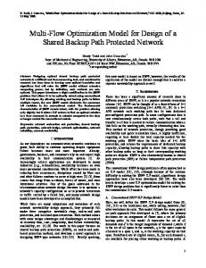
This example uses the model presented to map the flow of design information for the transmission in the Black & Decker VP480 cordless drill. The transmission is one subassembly of several that make up the drill and is located between the motor and the clutch head. A schematic of the drill is shown in Figure 5. The example begins with the recognition of the need for some transmission to provide an angular velocity reduction/torque increase between the motor shaft and the chuck. For this example, each of the design information states is discussed in the order shown in Figure 4 for two complete levels of refinement to the point where the transmission structure is formulated. This is not meant to indicate a prescriptive process model, but rather to illustrate the types of information formulated at each state for different levels of abstraction. The design information is presented in the form of an outline in the interest of clarity. Regarding units, the Black and Decker Cordless Drill is marketed with ratings in English units. In the interest of consistency, the example here is presented with English units. Metric equivalents are included for reference only. However, these are conversions performed after completion of the design and would not likely have been part of the original information flow. The use of English units in this example is significant because gears specified in an English standard are not interchangeable with gears specific in metric standard.
15
Table 1: SIMA Reference Architecture Design Process Model Expressed in the Flow of Design Information Model SIMA Reference Architecture Activity A12: A13:
Generate Product Specification Perform Preliminary Design
Design Information Transition Customer Needs → Specifications → Engineering Requirements
A133: Develop Preliminary Configurations
Engineering Requirements → {Family of Solutions}1..m {Family of Solutions}1..m→ … → {Evaluated Requirements0}1..m → Family of Solutions Family of Solutions → {Proposed Artifact}1..n
A134: Consolidate Configurations A135: Evaluate Alternative Designs
{Proposed Artifact}1..n → {Proposed Artifact}1..l {Proposed Artifact}1..l → … → {Evaluated Requirements1}1..l
A136: Select Design
{Evaluated Requirements1}1..l → Evaluated Requirements1
A131: Develop Functional Decompositions A132: Evaluate and Select Decompositions
Produce Detailed Designs A141: Design System/Component A142: Analyze System/Component
Comment
Generate conceptual design alternatives 1..m Evaluate conceptual designs at the highest (most abstract) level and select one Generate preliminary configuration alternatives 1..n for the selected functional decomposition Reduce number of preliminary configurations to l Evaluate reduced set of preliminary configuration alternatives at the next level of abstraction (increased detail). Select one design
A14:
A143: Evaluate System/Component Design A144: Optimize Designs A145: Produce Assembly Drawings
Evaluated Requirements1 → … → Proposed Artifactk Proposed Artifactk → … → Observed Behaviork → Evaluated Behaviork Evaluated Behaviork → Evaluated Requirements k
Artifact modeled to whatever level of abstraction, k, needed Analysis and behavior evaluation results appended to artifact description First iteration
Evaluated Requirements → 0 Evaluated Requirements k n Evaluated Requirements k → n Evaluated Requirements k+1
Iterate until design optimized at nth cycle
0
k
n
Assembly drawings may be more detailed than design representation May require further iteration(s)
A146: Finalize System/ Evaluated Requirementsn → Component Design Evaluated Requirementsn+1k+1 Subscripts denote multiple instances at same level of abstraction (alternatives or iterates). Superscripts denote different levels of abstraction. Ellipsis (…) denotes several consecutive state transformations k+1
7.1
First Pass Through the Design Information States
The design begins with the recognition of the need for speed reduction and torque increase from the motor to the chuck. The designers must establish the specifications and perform a preliminary feasibility search on possible solutions.
16
Control Lever Trigger Switch
Red Wire 2
Transmission Motor Bit
Chuck Base
Black Wire 3 Black Wire 2
Switch Housing Chuck Head
Black Wire 1
Red Wire 1 White Wire 1
Chuck Grip
Clutch Head
Battery 1 Battery 2 Battery Release
Figure 5: Power Drill Schematic
7.1.1
Customer Needs
The customer needs for the transmission are a subset of the overall customer needs for the drill. At the initial level of abstraction the designers may begin by listing those needs that appear to have relevance for the transmission design. 1. 2. 3. 4. 5. 6. 7. 8. 9. 10. 11. 7.1.2
Sufficient torque to (a) drill a hole, and (b) drive a screw (forward and reverse). Adequate speed for all operations. Variable speed for different operations. Manageable weight. Ergonomics: easy to grip, activate, etc. Balanced handling. Portable: cordless. Limit torque/don’t break the bit. Manageable size. Quiet. Cost competitive for home use market. Specifications
Specifications are characterized by measurable parameters with target values and constraints. Depending on the level of abstraction, the target values may not be known and may require further investigation to establish meaningful values. It is often useful to describe the rationale for each requirement and its target value.
17
1. Supply torque of “target value” for each desired operation. (a) Supporting factors: i. Material to drill: wood (hard to soft), metals, etc. ii. Bit size range: A. Wood up to 12.7 mm (1/2 in). B. Steel up to 10 mm (3/8 in). (b) Torque and speed values for drilling a hole. (c) Torque and speed values for driving a screw. 2. Cordless: battery power. (a) Influences motor size that has been previously standardized. (b) Influences input angular velocity: motor produces 1005 rad/s (9600 rpm) in low and 2010 rad/s (19200 rpm) in high. (c) Influences input torque: motor can produce 0.21 N•m (1.9 in•lb ). (d) Two VersaPak batteries supply 7.2 volts. 3. Output requires lower angular velocity, higher torque. (a) Values of rotational speed range for drilling, screwing, self-tapping screwing. (b) Two speeds 31.4 rad/s (300 rpm) and 62.8 rad/s (600 rpm) set by low/high switch on motor. (c) Need reverse. (d) Torque requirement of 6.78 N•m (60 in•lb) established by competitive benchmarking. 4. Weight limit of 140 g (6 oz)—minimize. Transmission is a subsystem of drill which governs the weight. 5. Balanced System. (a) Concentric center of gravity—longitudinal. (b) Concentric center of gravity—radial. 6. Stress limits on gearbox components. (a) Torque values influence components. (b) Forces influence component selection. 7. Size Restriction: minimize values. (a) Volume limits. (b) Length. (c) Width. (d) Shape. 8. Cost: total drill sales price of $45; transmission must be a small fraction of that. 7.1.3
Engineering Requirements
For this example at this level, it is not necessary to formalize all of the specifications into engineering requirements. The primary function to be explored is the need for angular velocity reduction. The form requirements are also limited to the minimum set needed for exploration at this pass. Function Requirements 1. Flow—Convert. 2. Input—Rotation.
18
(a) speed = 1005 rad/s (9600 rpm) (low) and 2010 rad/s (19200 rpm) (high). (b) torque = 0.21 N•m (1.9 in•lb) (max value). 3. Output—Rotation. (a) speed = 31.4 rad/s (300 rpm) (low) and 62.8 rad/s (600 rpm) (high). (b) torque = 6.78 N•m (60 in•lb) (max value). Form Requirements 1. Concentric shafts, mate with output shaft of motor, mate with input shaft of chuck, concentric center of gravity (symmetry). 2. Size restriction (a) Length < 50.8 mm (2.0 in). (b) Width < 38.1 mm (1.5 in). (c) Height < 38.1 mm (1.5 in). 7.1.4
Family of Solutions
The designers must explore possible solutions. In this case, the four alternative families of solutions shown below were generated. These alternatives represent broad concepts that suggest a form at a coarse level of abstraction. 1. 2. 3. 4.
Gearbox. Belt/pulley. Direct Coupling. Variable Speed Motor.
This example illustrates the exploration of the gearbox family of solutions. The other families of solutions would be explored in a similar manner. Refinements through the levels of abstraction are labeled with subheading numbers corresponding to the levels of abstraction. The intended behavior is set to produce the desired gear reduction of 32:1, corresponding to the gearbox specifications. The desire for colinear shafts and the space restrictions are included. At this exploratory stage of design, the designers search for a gearbox in a catalog. The behavior model is approximated by the model that is implicitly used in the catalog. The intent is to employ a technique to bind symbols in the exploration of the design alternatives. The description of the behavior model includes bound and unbound symbols. The bound symbols are those that have been instantiated at this level of abstraction. 1. Description (a) Bound i. Input speed = 1005 rad/s (9600 rpm) (low) and 2010 rad/s (19200 rpm) (high). ii. Input torque = 0.21 N•m (1.9 in•lb) (max). (b) Unbound i. Output speed. ii. Output torque. iii. Gear ratio. iv. Form. 2. Intended Behavior (a) Speed reduction/torque increase from gear ratio of nearly 32:1.
19
(b) Colinear shafts. (c) Size restriction. i. Length < 50.8 mm (2.0 in). ii. Width < 38.1 mm (1.5 in). iii. Height < 38.1 mm (1.5 in). 3. Behavior Model Approximated by the model used in the catalog; no need to observe behavior. 7.1.5
Proposed Artifact
The catalog search results in a large number of possible artifacts that satisfy the engineering requirements. It is learned that gear reductions are available from 3:1 to 3000:1. Gearboxes with colinear shafts tend to be cylindrical with size ranges of 25 mm to 43 mm (.96 in to 1.75 in) in diameter and 35.5 mm to 56 mm (1.4 in to 2.2 in) in length. Other information is garnered from the catalog search that can be categorized as unintended behavior because it was not listed as part of the intended behavior set. These characteristics will need to be explored for significance to this design problem. The catalog also listed a cost of $350 for a precision gearbox. The cost will need to be considered with respect to the design specifications. Notice that the bound and unbound symbols do not change for this level of refinement. The catalog search involved an exploration, but the design artifact was not bound. 1. Observed Behavior (a) Gear reductions available 3:1 to 3000:1. (b) Colinear shafts. (c) Sizes available: 25 mm to 43 mm (0.96 in to 1.75 in) diameter, 33.5 mm to 56 mm (1.4 in to 2.2 in) length. 2. Unintended Behavior: List of specification parameters from the catalog. (a) Gear ratio, number of gear clusters—affects ratio, not cost. (b) Diameter. (c) Colinear shaft. (d) Shaft size (input and output). (e) Direction of rotation. (f) Max rated output torque (starting and operating). (g) Backlash. (h) Weight. (i) Shaft end play (radial and longitudinal). (j) Moment of inertia of the input shaft. (k) Lubrication. (l) Gear tolerances. 3. Description—Bound and Unbound symbols do not change. 7.1.6
Evaluated Behavior
The evaluated behavior involves a comparison of the observed behavior with the intended behavior. The resolution is that a gearbox is acceptable at this level of abstraction; it can meet the intended behavior.
20
7.1.7
Evaluated Requirements
The evaluated requirements involve comparing the results from the behavior model with the engineering requirements. At this level of refinement, the gearbox alternative shows promise but the cost of $350 violates the overall cost constraint of $45. 7.2
Second Pass Through the Design Information States
The decision has been made to explore the gearbox family of solutions in greater detail. New information has been garnered from the first level of abstraction. The second pass through the design information states will require refinement at each of the states with consideration given to what was just learned. 7.2.1
Customer Needs
The customer needs do not change. The cost of $350 discovered from the catalog exploration forces the designer to recognize a total retail sales cost for the drill of $45. The transmission must be a small fraction of this. 7.2.2
Specifications
The engineering requirements are revised with consideration of the characteristics included in the catalog. These new characteristics are rated on a level of importance to the design, as high, medium, or low. 1. 2. 3. 4. 5.
6. 7. 8. 9. 10. 11. 12. 13.
Production cost for transmission with (100,000 lot size limited to $5)—high. Gear ratio, number of gear clusters—affects ratio not cost—high. Diameter: meet size restrictions on the housing—high. Colinear shaft—high. Shaft size (input and output)—low. (a) Input must mate with motor output shaft. (b) Output must mate with chuck. Direction of rotation—low. (a) Must coordinate with motor polarity. Max rated output torque (starting and operating)—high. (a) Established previously. Backlash—low. (a) Not important for consumer market. Weight—high. (a) Component weight is part of overall weight. Limit weight to 8 oz. Shaft end play (radial and longitudinal)—low. Moment of inertia of the input shaft—low. (a) Motor must be able to overcome moment of inertia for starting. Lubrication—low. (a) Do not expect the user to maintain. Self-lubricating or tightly sealed. Gear tolerances—low. (a) Play not likely as important for this application.
21
7.2.3
Engineering Requirements
The engineering requirements remain mostly unchanged. In the first pass, the size restriction for the form requirement was stated for a volume in the form of a box. The catalog exploration indicated that gearboxes with colinear shafts are in the shape of a cylinder. This change seems appropriate and the form requirements are updated. 1. Function Requirements—unchanged 2. Form Requirements (a) Alter size restriction to consider cylindrical shape. i. Length < 50.8 mm (2.0 in). ii. Diameter < 38.1 mm (1.5 in). (b) Other Form Requirements stay the same. 7.2.4
Family of Solutions
The designers decide to explore their own design of a planetary gearbox. As described in Section 5, they explore design alternatives by a series of interactions through various levels of abstraction. There is an iterative interplay between the family of solutions and the proposed artifacts to satisfy the intended behavior. The planetary gearbox family of solutions establishes the abstract form shown in Figure 6. This abstract form includes the various components such as the sun, planets and ring gears that are connected by an arm. The sizes of the gears will establish the gear reduction behavior of the gearbox. The behavior model incorporates information on gear design. The general behavior model for the solution family is used for all artifact instances. 1. Description (a) Bound—same as level 1. (b) Unbound. i. Sun Gear Size. ii. Planetary Gear(s) Size. iii. Ring Gear Size.
case/cover
shaft 2
shaft 1
sun
planet
ring
bearing
Figure 6: Basic Planetary Gear System
22
2. Intended Behavior (a) Gear ratio of 32:1. (b) Output torque of 6.78 N•m (60 in•lb) from a motor torque of 0.21 N•m (1.9 in•lb). (c) Diameter less than 38.1 mm (1.5 in). 3. Behavior Model The derivation for the angular velocity reduction of planetary gear trains can be found in a kinematics text such as [12]. The information model would contain the derivation, but it is not reproduced here in the interest of space. The general equation for a planetary gear train of this configuration is expressed as:
N ring Dring ω in =1+ = 1+ ω out N sun Dsun 7.2.5
(1)
Proposed Artifact
The family of solutions model now contains bound and unbound symbols and a behavior model. With this information the designers can explore alternative proposed artifacts by binding additional symbols. 7.2.5.1
Single Planetary Gear Train
The first alternative involves the selection of a single planetary gear train. The parameters describing the gear sizes are obtained from a design repository. Counting the number of teeth on each of the gears results in the following: 1. Description The Bounded Description is summarized in the table below: 54 Sun N1 27 Planets N3 108 Ring N4 2. Behavior Model Equation 1 from the family of solutions’ behavior model
N ring ω in =1+ ω out N sun
(2)
ω1 N 108 =1+ 4 =1+ =3 ω2 N1 54
(3)
7.2.5.1.1 Observed Behavior
The observed behavior for the single planetary gear train resulted in a gear reduction of 3:1. 7.2.5.1.2 Evaluated Behavior
The evaluated behavior is summarized in the following table:
23
Behavior
Reduction
Intended
32
:1
Observed
3
:1
This instantiation of a single gear planetary gear train is unacceptable. Insight garnered from the behavior model indicates that the ring gear must be significantly larger than the sun gear to produce the desired reduction. This insight will be used for the next instantiation. 7.2.5.2
Revised Single Planetary Gear Train
In the second instantiation of a proposed artifact the designers establish the size of the sun gear and then determine the size of the ring gear that will provide a gear ratio of 32:1. The designers are able to call upon the behavior model from the planetary gearbox family of solutions. This reformulation of the description assigns a new sub-level for the proposed artifact. 1. Description To obtain a bound description, establish a desired gear ratio of 32:1 and set the number of teeth on the sun to 9. Planets
N3
unbound
Sun
N1
9 bound
Ring
N4
unbound
2. Behavior Model For a desired gear ratio of 32:1, Equation (1) from the family of solutions’ behavior model indicates that:
N ring Dring ω in =1+ = 1+ ω out N sun Dsun
(4)
ω1 N = 32 = 1 + 4 ω2 9
(5)
Solving for N4 results in: N4 = 279
(6)
D4 = 31 D1
(7)
Also,
D1 =
38.1 mm = 1.23 mm = 0.048in 31
(8)
7.2.5.2.1 Observed Behavior
The behavior model was used to force the desired gear reduction of 32:1. The ring gear would need to have 279 teeth and be 41 times larger in diameter than the sun gear. For a ring diameter of 38.1 mm (1.5 in), the sun gear diameter would be only 1.23 mm (0.048 in)!
24
7.2.5.2.2 Evaluated Behavior
The evaluated behavior is summarized in the table below: Behavior Intended
32:1
Observed
32:1
Unexpected
Sun gear diameter of only 1.23 mm (0.048 in)
Resolution
Acceptable gear ratio
The behavior evaluation indicates that this planetary gearbox will provide the desired gear ratio which is the intended behavior under investigation. However, there is an unexpected behavior in that the sun gear diameter must be only 1.23 mm (0.048 in) in order to satisfy the behavior requirement of a diameter less than 38.1 mm (1.5 in). 7.2.5.2.3 Evaluated Requirements
The proposed artifact satisfies the intended behavior established for the family of solutions. In addition to the function requirement of the desired gear reduction, there is a form requirement that considers the size of the system. In order to meet the form requirement of a gearbox diameter less than 38.1 mm (1.5 in), the sun gear would need to be only 1.23 mm (0.05 in) in diameter. This is too small and unacceptable. The resolution from the requirements evaluation is then to reconcile the description and explore another proposed artifact. 7.2.5.3 Two Linked Planetary Clusters
For the next level of refinement of the proposed artifacts, the designers decide to explore the possibility of nesting two planetary gear trains. Each gear train cluster will provide part of the gear reduction. Because the gear reduction for each cluster is lower, the relative size of the sun gear to the ring gear will not have to be as large. The intent is to produce a sun gear of acceptable size. Each gear cluster is of the same form described by the planetary gearbox family of solutions. The behavior model for this alternative can draw from the general planetary gearbox behavior model. However, the new description includes a formulation that connects the two planetary gear trains. 1. Description The new alternative consists of two planetary gear trains and is illustrated in Figure 7. The input shaft is attached to the first planetary gear train cluster at gear 2. The output shaft is attached to the second planetary gear train cluster at arm 6. The internal ring gear 7 is common to both gear trains and the arm 4 of the first cluster is attached to the sun 4 of the second cluster. The bound description includes the numbers of teeth for each gear indicated in the figure. 2. Behavior Model Use the following numbering system for the two gear train cluster components: Cluster 1
No. of Teeth
Cluster 2
No. of Teeth
Sun
2
9
4
9
Arm
4
-
6
-
Planet(s)
3
17
5
17
Ring
7
42
7
42
25
Ring 7 (42T) 4 (Arm)
5 (17T)
3 (17T) 2 (9T)
6 (Arm)
In
4 (9T)
Out
Figure 7: Two Linked Planetary Clusters
Equation (1) from the family of solutions’ behavior model for the two planetary gear train clusters results in:
N ring Dring ω in =1+ = 1+ ω out N sun Dsun
(9)
Cluster 1:
N 42 ω2 =1+ 7 =1+ = 5.67 N2 9 ω4
(10)
Cluster 2:
N 42 ω4 =1+ 7 =1+ = 5.67 N4 9 ω6
(11)
Linking equation (10) with equation (11) through the common w4 results in:
ω in ω 2 = = 32.1 ω out ω 6
(12)
7.2.5.3.1 Observed Behavior
The proposed artifact demonstrates a gear reduction of 32.1:1. 7.2.5.3.2 Evaluated Behavior
The behavior comparison is summarized as follows: Behavior
Gear Reduction
Intended
32:1
Observed
32.1:1
Variation
0.1
Resolution
Acceptable
26
The observed gear reduction of 32.1:1 indicates a variation of 0.1 from the intended gear reduction of 32:1. This variation will likely not have a significant effect on the performance of the gear train. The designers decide that this variation is acceptable for this level of abstraction. The proposed planetary gearbox with two planetary clusters meets the intended behavior. 7.2.5.3.3 Evaluated Requirements
The intended behavior was to provide a gear reduction of 32:1. This value was derived from the requirement of a desired output speed given a known input speed. It is actually the output speed and the accompanying output torque that are of most interest for the design. Therefore, it is necessary to explore how the proposed gearbox meets those requirements. 1. Motor speed of 1005 rad/s (9600 rpm) (low) and 2010 rad/s (19200 rpm) (high) results in output speed of 31.3 rad/s (299 rpm) (low) and 62.6 rad/s (598 rpm) (high). 2. Input torque from motor of.0.21 N•m (1.9 in•lb) results in output torque of 6.89 N•m (61 in•lb). 3. Ring diameter of 38.1 mm (1.5 in) will result in a sun gear diameter of 8.1 mm (0.32 in). The designers decide that each of these results is acceptable at this level of abstraction. The doublecluster planetary gearbox will satisfy the engineering requirements within an acceptable variation. 7.3
Continued Design of the Gearbox
The design at this level of abstraction now contains an adequate description to satisfy the function requirement convert input rotation to output rotation. Other specification requirements will dictate the formulation of more refined engineering requirements. For example, the issue of input and output torques will guide the determination of the number of planets as well as the selection of diametral pitches and materials for the gears. Refinement of the artifact will continue through the iterative process to further levels of abstraction. The final artifact design will contain a complete description of the bound symbols that characterize the form, function and behavior. The discussion now turns to the issue of representing product development knowledge. This paper will return to the subject of the information flow model in Part D, which provides conclusions and a discussion of future work.
27
PART C: REPRESENTATION OF KNOWLEDGE IN PRODUCT DEVELOPMENT 8
INTEROPERABILITY AND PRODUCT DEVELOPMENT
As described in Part A, in the past product development was often done within a single company by colocated design teams. In more recent years, there has been a shift in product development paradigms. Product development is being done more often by geographically and temporally distributed design teams. There is a high level of outsourcing, not only of manufacturing but also of actual product development efforts. Product development across companies, and even within a single company, is often done within a heterogeneous software tool environment. The Internet and intranets are supplanting paper and telephones as a means of exchanging product development information. As a result of this new product development paradigm, there is a greater need for software tools to effectively support the formal representation, capture and exchange of product development information. The existing generation of computer-aided engineering (CAE) software tools has undeniably revolutionized product development in contrast to methods used before the advent of these technologies. Nevertheless, the current generation of product development software tools addresses the needs of traditional product development processes, and does not adequately support the needs of industry’s new paradigm described above. People are exchanging information across distributed design teams and corporate boundaries earlier, and reusing information to a greater extent. But because existing software tools do not capture a broad spectrum of product development information, these exchanges occur informally (face-to-face across a table, by phone, by paper). It is a lack of formal representations for product development information that creates a significant barrier to its effective capture and exchange. In other words, engineers are getting by not with the support of existing software tools but despite the lack of support from them. The current generation of software tools is not designed to support at a formal level the kinds of interactions that occur, to the extent that engineers would prefer. These views are not held exclusively by the authors, but are representative of industry input obtained at several workshops held at NIST in recent years: The NIST Design Repository Workshop [13], Tools and Technologies for Distributed and Collaborative Design Workshop, and the NIST/ATP Workshop on Intelligent and Distributed CAD [14]. The CAD/CAM/CAE software industry is ultimately a customer-driven one. It is therefore expected that as needs (such as those identified previously) mount, a new generation of tools will emerge to address these needs. The question that remains unanswered is: at what cost? Despite the acknowledged benefits of today’s tools, their widespread use has in many cases come at great expense to industry as a whole because of a lack of interoperability between tools. While these expenses do not approach the level of savings resulting from the use of CAE technologies, they do offset the overall benefits. These expenses are inevitably passed on to industry customers, and ultimately to consumers. A study performed by the NIST Strategic Planning and Economic Assessment Office conservatively estimates the economic cost due to lack of interoperability in the United States automotive supply chain alone at $109 per year [15]. The study also estimates costs in the U.S. aerospace, shipbuilding, and construction machinery industries at about 400 x 106 dollars per year (for each of those sectors), assuming the interoperability costs are proportional to those in the automobile industry. As the complexity of products increases and product development becomes more distributed, new software tools will begin to cover a broader spectrum of product development activities than do the traditional mechanical CAD systems. Accordingly, the ability to capture, in an effective and formal manner, additional types of information will become a critical issue. This paper develops a vision of nextgeneration product development systems and provides a core representation for product development information on which future systems can be built. This paper does not put forth specific technologies that will be incorporated into next-generation tools, but rather seeks to address potential interoperability
28
problems proactively, rather than reactively, by providing this core as a foundation for improved interoperability among software tools in the future. The costs of poor interoperability among today’s tools are likely to be compounded significantly in the future if the problem remains unaddressed. The work presented in this paper addresses a fundamental problem whose solution can impact on the order of $109 of costs to industry. The economic benefits notwithstanding, the effort of developing a generic knowledge infrastructure for the next generation of tools is one that neither industry nor the CAD/CAM/CAE vendor community is likely to undertake alone. Historically, software tool vendors have considered proprietary data representations—a significant source of interoperability problems—as part of their competitive advantage. Working to eliminate the barriers to interoperability is often viewed by a software vendor as something that will make it easier for customers to purchase and use a competitor’s products rather than those sold by that company. This perceived threat to a competitive advantage provides a disincentive for vendors to address interoperability problems. Indeed, this is one of the main reasons that efforts to integrate data exchange standards such as ISO 10303, informally known as STEP (Standard for the Exchange of Product Model Data) [16] into the existing generation of software tools has met with resistance from vendors despite requests from, and clear benefits to, their industry customers [13]. While engineering companies in industry stand to benefit from work along these lines, they too are unlikely to undertake such an effort. This is a result of industry research and development trends that have shifted from basic research and development (R&D) to project-oriented R&D. This change makes it difficult for a company to use project-specific budgets to fund work that is acknowledged as beneficial, but has diffused impact. What limited funds are available for generic R&D are generally applied to problems where benefits can readily be mapped either to a set of related projects, or to the corporate bottom line, in a short time frame. These cultural issues have served as obstacles to the development of technical solutions to interoperability problems in existing tools, and run the risk of similarly affecting the next generation of software systems. The National Institute of Standards and Technology has U.S. industry as its primary customer and works to address problems that have significance to industry, but that companies are not likely to solve on their own for one reason or another. NIST’s emphasis is on economic impact to industry and society on a broad level rather than a corporate bottom line. Furthermore, NIST is not biased toward a particular class of problems, company, or industry sector, focusing instead on generic solutions that have broad-based applicability in industry. As a result, NIST is uniquely situated to invest in an effort to anticipate and address interoperability needs in next-generation product development systems. Existing standards efforts focus on enabling interoperability among tools that address a given product development activity (such as geometric CAD). However, the more significant demand in nextgeneration tools such as OpenADE will be for representations that allow information used or generated in various product development activities to feed forward and backward into others by way of direct electronic interchange. The objectives of the present work are to develop representations of information that are unavailable in traditional CAD/CAM/CAE tools, to support exchange of knowledge in the new product development paradigm, and to help avoid a proliferation of proprietary formats in next-generation commercial software tools. This work is not itself a standards development effort. Rather, it is an attempt to identify needs and provide a generic information representation core that can serve as a foundation for development of new systems, and at some point for future standards development efforts. We do not propose technologies that affect implementation-level development of software tools, but provide an infrastructure that will facilitate the capture and exchange of information among commercial tools that use it as a starting point and build upon it.
29
9
NEXT-GENERATION PRODUCT DEVELOPMENT TOOLS
The basic assumption underlying this work is that the change in product development paradigm identified in the introduction will lead to a new generation of software tools. This next generation of tools will be driven by an increased industry focus on representation, capture, and exchange of product information and product development knowledge. Existing computer-aided engineering tools are focused primarily around geometric CAD and analysis, with some tools supporting CAM activities such as process planning. Next generation systems will enable the capture of a broader variety of product information, and will support a wider range of product development activities than do existing tools. The vision held by some for future product development tools is that of a monolithic software system. In this vision, the product development process will be supported by a single integrated application suite. Such a tool would attempt to address the needs of the new product development paradigm, allowing teams that are potentially distributed geographically or across corporate boundaries to access tools and data at different phases of product development in order to produce a product (see Figure 8). This vision, though not an uncommon one, has a number of drawbacks associated with it. In general, since a monolithic system is intended to be as complete a solution as possible, less emphasis is put on interoperability with other systems. Because interoperability becomes a problem, collaboration with users of other tools becomes difficult. What has happened in some cases among the existing generation of tools is that a large company will make a statement to the effect of: “If you want to do business as part of our supply chain, you will use this particular software tool.” Since monolithic systems tend to be expensive, among those priced out of the running are many small and medium sized businesses that form a large segment of the industry community. These limitations stifle competition, resulting in prices to the
Monolithic system Figure 8. Monolithic Product Development System.
30
customers and end users that are higher than they might otherwise have been. Such systems also tend to tie users to one vendor, making the migration to a new tool suite problematic should a better system come along at some later point in time. And lastly, a monolithic tool suite will often result in a suboptimal set of technologies. It is unlikely that a system that provides technologies for a variety of activities will be the best at what it does in all cases, particularly when a solution that might be the best solution for one company may not be for another. Some software vendors, rather than working to build a monolithic system, are working with a business model under which they establish relationships with other software companies and work to design interfaces between tools to make integration more seamless. This philosophy has the potential to offer greater customization of software tool suites. The drawback, as a practical matter, is that choice is likely to remain limited, this time to a set of companies who have established these strategic partnerships. In our view, the ideal next-generation systems for product development will be those with which individual companies, or teams involved in given product development activities, can collaborate using a heterogeneous set of software tools, and still exchange information meaningfully and pass knowledge between various phases in the process. Assuming the interoperability barrier can be overcome, this vision avoids several of the disadvantages associated with a monolithic system. Companies would not be required to standardize on the same software platform in order to collaborate on product development. Smaller companies using individual software tools due to limited resources would still be able to compete to be part of a larger company’s supply chain. Larger companies would be able to assemble what they consider to be the best suite of tools from a selection of existing software products (possibly from competing vendors), and would be able to migrate more easily to new tools, although some effort would still be involved in doing so. We define the Engineering Context as the entire body of information and engineering knowledge that evolves throughout the product development process. Under the vision of a customizable and flexible product development tool suite, multiple software tools—potentially from competing vendors—are used during different product development activities at various stages of the design process, creating, adding to, and modifying the engineering context. Information generated by some tools during some activities will be used by other tools at other stages of the design process. In order to achieve the interoperability required by this vision, a tool that requires information created by a different tool must be able to receive that information irrespective of which tool created it. This, in turn, requires that the formal representation of product information (or at least that portion of the engineering context that is to be shared with other applications) be available in a standardized form. It is important to note that tools need not be able to read native data files created by other systems; what is required is only that a tool be able to serve information in a format that other tools can interpret. Thus, although vendors would need to agree to use this standardized format for exchange of engineering information, they would not be required to standardize on native or application-internal data formats. The vision of a flexible product development tool suite is shown in Figure 9. In some cases, tools from a single vendor may be designed to share a common database as is illustrated with the users in the top half of the figure. In other cases a single tool may have an individual database as shown in the bottom left portion of the figure. The “X”es in the figure denote the data exchange interfaces required to exchange or externally store product information in a standardized format. Although it is not necessary for vendors to adopt the standardized representation as their native representation, those that do would not require a translation step to exchange or store data externally. The software tool in the bottom left portion of the figure does not show a data exchange interface for this reason. The large database at the bottom of Figure 9 represents the engineering context (the cloud represents the fact that the characterization of the engineering context as a single database is meant figuratively and may
31
x
x
Intranets/Internet
Figure 9. Product Development Using a Heterogeneous Suite of Software Tools.
not be indicative of its true instantiation). Whether the actual instantiation of the engineering context takes the form of a centralized database, a distributed database, a collection of individual files created by separate applications, etc., is an implementation-level issue. The focus of this work is not on implementation, but on providing a generic core for representing the engineering context as a basic foundation for interoperability. Regardless of the form that the engineering context embodies, for a tool to be able to retrieve and interpret information generated by other tools in a heterogeneous software environment, interoperability issues must first be addressed at the information representation and exchange level. 10 REPRESENTING THE ENGINEERING CONTEXT 10.1 Technical Approach
The preceding discussion presents a vision that motivates the development of a foundation for representation of design information that is non-proprietary and not tied to a single vendor. From the interoperability perspective, in an ideal world all vendors would use the same representation making interoperability problems irrelevant. Realistically, it is not likely that all CAD/CAM/CAE vendors will agree on a common product information representation, or even that they will want seamless exchange with competing systems. Nevertheless, work toward this goal is still very valuable for several reasons. First, agreement on requirements and implementations to any extent is better than none. To whatever degree a specification is adopted in multiple implementations, exchange of information will be that much less problematic even if a total exchange is not seamless. Addressing the problem in anticipation of nextgeneration systems, rather than in response to failings among those systems after they have been
32
developed, increases the likelihood that common solutions will be adopted. Second, assuming realistically that some interoperability problems will exist in the future, it is also probable that some sort of standards development efforts will ensue in response. The work being done here can provide a starting point for those future standards. For both of these reasons, simplicity is a key requirement for the representation being developed. Simplicity also makes a proposed representation more appealing to users. This is a critical issue since vendors must believe that a broad market will exist before they would consider using such a representation. Because of a need for broad appeal among potential customers, a product information representation should be domain-independent and should not be tied to any one product development process. Because the information flow modeling effort described in Part B identified common classes of information used by designers, activities that were common to various design processes (even though the sequences of those activities were often not common to different processes), that effort provided significant input into developing the actual content requirements for the information representation presented here. Based on these issues, in order to enable the vision of next-generation product development discussed earlier, the goal that was set for this effort was to develop formal representation that could form the core of the engineering context discussed above. This core is intended to be an abstraction of concepts that are common across many design activities. The broader engineering context would include this common core along with additional concepts (objects, relationships, attributes, etc.) such as activity- and domainspecific extensions and specializations that may not be common to many activities. The core would provide interoperability across activities, while extensions to the core might or might not require additional translators or interpreters depending on the extent of adoption among different software tools. The requirements for the core were to develop a knowledge representation that is: •
Not tied to a single vendor software solution;
•
Open and non-proprietary;
•
Simple and generic;
•
Extensible by allowing augmentation of the core with additional concepts to create a broader engineering context;
•
Not dependent on any one product development process;
•
Capable of capturing that portion of the engineering context that is most commonly shared in product development activities.
The representation was also intended to provide interoperability among four in-house research and development projects: 1. The NIST Design Repository project, developing a distributed framework to support the creation of design repositories, the next generation of design databases [3, 4]; 2 . The Design-Process Planning Integration project, developing interface specifications and prototypes to enable manufacturability analysis during conceptual product design [17]; 3. The Design for Tolerancing of Electro-Mechanical Assemblies project, working to advance the use of tolerancing at early stages of design and to investigate the best use of available methods of tolerance analysis and synthesis [18]; 4. The Object-Oriented Distributed Design Environment project, developing a software prototype of such a system.
33
Each project team had been proceeding to develop its own product model, with little or no interaction among the projects. A comparison of the product models developed or proposed by the four projects showed that of the 133 terms (object and attribute names) used in the models, 99 terms (74%) appeared in one model only and only three terms (2%) appeared in all four models. This comparison excludes terms that are specific to the domain of one project only, such as process- and tolerance-related terms. It therefore appeared that there was not much commonality. The next step was the development of a core combined product model that could be shared across projects and extended as needed to suit the concerns of the individual projects. Although the core model most closely resembles the model originating from the NIST Design Repository project, terms from the other three projects were also incorporated, showing the synergy provided by broader exposure and discussion. The examination of multiple independently-developed models, abstracting out the commonalities, and distilling their basic information content, led to a more generic and extensible representation than any one of them had previously provided. The representation that emerged is proposed as an information transfer mechanism for next-generation product development tools, either in the basic form presented in this paper or as the “foundation” or base-level representation of the multilevel design information flow model presented in Part B. The section that follows presents the core representation that resulted from the effort described above. A comprehensive overview of the general research area of representation of design knowledge can be found in (Szykman et al., 2001), and is not repeated in this paper. 10.2 The Core Representation
The core representation consists of classes of objects and relationships. The full listing of all classes in the core representation is shown in Appendix A. In the text that follows, names of classes are capitalized and names of attributes are not. The syntax and common characteristics of the classes are discussed first, followed by their semantics. The object class hierarchy is shown in Figure 10.3 Syntactically, all object classes are specializations of the abstract class DRP_Object, which has attributes name, information, and sources and destinations of references and relationships (discussed below). The abstract class Restricted_DRP_Object specializes the DRP_Object class and has additional attributes constrained_by and is_required_by serving as links to Constraints and Requirements, respectively. The specializations of the DRP_Object class are the Artifact, Behavior and S p e c i f i c a t i o n classes; specializations of the abstract class Restricted_DRP_Object are the Function, Flow, Form, Geometry and Material classes. The Function class further specializes into the Transfer_Function class. The attributes of the object classes are discussed below in the context of their semantics. The relationship class hierarchy is shown in Figure 11. Similarly to objects, all relationships are specializations of the abstract class DRP_Relationship, with attributes name and information. The specializations are the Requirement, Reference, Constraint and Set_Relationship classes, the latter further specializing into Directed_Set_Relationship and Undirected_Set_Relationship classes. In order to make the representation as robust as possible without having to predefine all possible attributes that might be relevant in a given set of domains, the core representation is limited to those attributes required to capture generic types of product information and to create links and associations among the entities shown in Figures 10 and 11. The representation intentionally excludes attributes that are domainspecific or entity type-specific. Such attributes can be represented, but are not explicitly built into the schema. Instead, each object and relationship has an Information entity associated with it. The class
3
Abstract classes in the figure are denoted by “(a)”. An abstract class is a class for which instances cannot be created, but which exists for the convenience of grouping attributes that are common to all of its subclasses so that these attributes can be inherited by the subclasses.
34
DRP_Object (a)
Artifact
Flow
Restricted_DRP_Object (a)
Form
Function
Behavior
Geometry
Specification
Material
Transfer_function Figure 10. Object Class Hierarchy.
DRP_Relationship (a)
Requirement
Set_Relationship (a)
Directed_ Set_Relationship
Reference
Constraint
Undirected_ Set_Relationship
Figure 11. Relationship Class Hierarchy.
Information is a container for all detailed information, consisting of a brief textual description, a textual documentation string (which typically provides a file path or URL referencing more substantial documentation than is given by the brief description), a methods slot for the methods operating on the object, and a properties slot that contains a set of attribute-value pairs stored as strings. Domain- or entity type-specific attributes are represented using the properties attribute. This lack of specialization of entities results in a small number of entity definitions that are broadly applicable. As will be illustrated in an example below, this allows the representation to be used to represent a 9-Volt electric motor and a 9-Volt electrical current flow without predefining a domain-specific attribute called voltage in either of the entity definitions.
All specializations of the abstract class DRP_Object except Flow have their own decomposition hierarchies, represented by attributes such as subartifacts/subartifact_of for the Artifact class. In addition, most of the objects and relationships also have an attribute called type, a symbolic classifier. All of the entity classes that have a type also have an individual hierarchical taxonomy of terms associated with them. These terms are generic enough to designate a broad variety of engineering artifacts, and yet concise enough to provide a manageable standardized vocabulary. The type classifier is a string corresponding to one of the terms within a given taxonomy. For example, the engineering function “Convert” is one of numerous subtypes of “Transform-function,” which is in turn one of several subtypes of “Function.” Another way to view this is that several of the entities in the representation have their
35
own individual generic engineering classification hierarchies that are unrelated to the entity class hierarchies shown in Figures 10 and 11. The motivation for providing typing information and associated taxonomies on which to draw for artifact modeling is twofold. The standardized vocabulary facilitates indexing and retrieval of product knowledge for design reuse. The classification of an entity (e.g. an Artifact or Function or Flow) within its associated taxonomy allows a software system to reason about these entities based on knowledge of their type. In other words, knowing that an entity is an Artifact gives you information at one level, but knowing that an artifact is a motor allows more sophisticated reasoning. The type attribute is provided as part of the infrastructure for product information representation with the expectation that it could be used in these ways in future software tools. A more substantial discussion of taxonomical issues and examples of taxonomies for engineering function and flows are given in [19]. Discussion of the mechanisms for indexing, retrieval and reasoning based on type knowledge in future systems are beyond the scope of this paper. Turning to semantics, the key object class is the Artifact. It represents a distinct entity in the design, whether that entity is a feature, component, product, subassembly, or assembly. All such entities can be represented and interrelated through the subartifact/subartifact_of containment hierarchy. The artifact’s attributes, other than the common ones described above, refer to the Specification responsible for the Artifact and the Form, Function and Behavior objects constituting the Artifact. A Specification is an object that contains information relevant to an artifact that is derived from customer needs. An artifact Specification drives requirements among one or more other Function, Form, Geometry, Material and Flow entities via a requirement relationship (discussed below). An additional attribute, Config_Info, links the Artifact to an element of the class Config_Info, which represents design process-related attributes of the artifact, such as state, level (as used in the information flow model), and version, in an interactive environment. The Form, Function and Behavior classes a conceptual decomposition of an artifact that is common in the artificial intelligence literature. A specialization of the Function class is the Transfer_Function class, which represents a transformation between one or more flows (e.g., current, liquid, energy) and explicitly refers to the Flow entities involved using input_flow and output_flow. The Flow class identifies the flows involved and references the Artifacts corresponding to a flow’s source and destination. The Form class refers to the two principal aspects of the form, namely the artifact’s Material and Geometry. This subdivision was introduced into the core model because some of the intended applications, such as the Design-Process Planning Integration and the Design for Tolerancing projects tend to treat these two aspects quite differently (e. g., the task of material selection for a given function and geometry in process planning). A Requirement entity is a one-to-many relationship between a Specification and a set of Function, Form, Geometry, Material and Flow entities governed or otherwise affected by that specification. Similarly, a Constraint entity is viewed as an undirected set membership relation among the constrained Function, Form, Geometry, Material and Flow entities. If it is intended to represent a mathematical equality or inequality constraint, the properties slot of the constraint can store the attributes contained in the constraint as well as the relational operator. The Undirected_Set_Relationship class simply sets up set membership relationships among objects, while the Directed_Set_Relationship class identifies a special member of each set. Finally since, as stated above, the representation allows for hierarchies of Function, Form, Geometry, Material entities independent of each other and of the artifact’s containment hierarchies, it was found prudent to introduce the Reference class of one-to-one directed relationships between referring and referred_to objects as a means of navigating between elements of such hierarchies.
36
As can be seen from the above discussion, the core representation is by no means minimal. The set of object classes largely reflects traditional terms used in formal design descriptions and models; it was felt that any further abstraction would have eliminated semantically meaningful terms. The number of relationship classes could have been reduced since requirements or constraints could have been represented using the more generic set relationships. However, it was felt that the terms “requirement” and “constraint” are themselves semantically meaningful and should be retained. 10.3 Example: Power Drill Motor
This section presents an electric motor that is a component in a power drill as an example to illustrate the use of the product knowledge representation core. What follows is a set of instances of several of the entity classes described above. The intent of this example is to provide a flavor of how the simple generic entities that comprise the representation core can be used to model a complex engineering product, as well as what the entities that populate a product information base look like. This section does not attempt to provide a complete representation of the power drill motor (as is evidenced from the fact that the entities shown contain pointers to various other entities that do not appear in the example), nor does it attempt to provide a comprehensive set of examples that covers every kind of entity discussed above. Note that although entities in an artifact model always contain all the attributes defined for that entity (see Appendix A) irrespective of their value, in this example attributes having default or NULL values have been omitted for reasons of brevity. The first entity below is an Artifact representing the drill motor. This motor is a subartifact_of another Artifact representing a power transmission (not shown), which has several other subartifacts in addition to the motor, including a chuck and a gearbox. The power transmission itself is one of several subartifacts of the power drill itself. It is in this way that the physical decomposition of an engineering product is represented. The drill motor itself does not have subartifacts, indicating that it is not further decomposed into subassemblies and components. The reason for this is that although the motor is composed of multiple parts, the company that manufactures the drill buys the motors as original equipment manufacturer (OEM) catalog parts, and thus treats the motor as a single component. Were this not true, there would be nothing to prevent the representation of each of the motor components as subartifacts of the motor. Artifact { name information type config_info function form behavior subartifact_of is_source_of is_destination_of }
Drill_motor Drill_motor_info Motor Drill_motor_config Drill_motor_function Drill_motor_form Drill_motor_behavior Power_transmission {Motor_rotation} {Battery_current}
The motor shown above includes a reference to a Function object, providing a pointer from the artifact domain into the function domain. The next entity represents the motor Function, which is to “convert.” The input_flow and output_flow to the Function are an electrical current and rotational motion respectively, shown in the entities that follow. Each of the Flows has pointers to a source and destination, which are Artifacts, thereby providing pointers back from the function domain to the artifact domain. The information captured in aggregate is that the motor has a function, which is to
37
convert electrical energy that flows from the battery pack connector cable to the motor, into rotational motion whose source is the motor and whose destination is a gearbox. Transfer_Function { name information type function_of_artifact input_flow output_flow } Flow { name information has_constraint type source destination is_input_of is_output_of } Information { name properties }
Drill_motor_function Drill_motor_function_info Convert Drill_motor {Battery_current} {Motor_rotation}
Battery_current Battery_current_info Battery_current_constraint Current Battery_pack_connector_cable Drill_motor {Drill_motor_function} {Battery_pack_connector_cable_function}
Battery_current_info {“V = 9 Volts”}
The next two entities below represent a Constraint that is applied to the battery current requiring that the electrical input to the motor should be at 9 Volts. This previous entity above represents a property of the battery current, which indicates that the voltage of the battery is 9 Volts. Thus, the constraint is satisfied. Constraint { name information type constrains } Information { name description }
Battery_current_constraint Battery_current_constraint_information Plaintext Battery_current
Battery_current_constraint_information “Electrical input to motor should be at 9 Volts.”
38
Flow { name has_constraint type source destination is_input_of is_output_of }
Motor_rotation Motor_rotation_constraint Rotational_motion Drill_motor Gearbox {Gearbox_function} {Drill_motor_function}
The remaining two entities are the motor function Behavior and its associated Information entity. In this example a second-order ordinary differential equation model, written in c, is available to simulate the motor behavior. Behavior { name information type behavior_of_artifact } Information { name description methods }
Drill_motor_behavior Drill_motor_behavior_info Second_order_ODE Drill_motor
Drill_motor_behavior “Ordinary differential equation model of motor behavior” {“generic-motor-simulation.c”}
10.4 Implementation
The product representation core presented in this paper is being adopted as the basis for software tool implementations in the Manufacturing Systems Integration Division (MSID) at NIST. The NIST Design Repository project, geared toward providing a technical foundation for the creation of heterogeneous information repositories that support the representation, capture, sharing and reuse of corporate design knowledge is an example of such an effort. This project has developed a prototype implementation that includes web-based interfaces for authoring, updating and modifying design repositories [3, 4]. As part of this ongoing effort, a second prototype implementation is currently in progress. This new prototype will be built using the product development representation core presented in this paper. The representation core has been mapped into a relational data model (i.e., a set of relational database tables) and an initial relational database has been generated using Oracle8. A simple Java™-based browser interface is currently available. A distributed client-server architecture is being developed that will enable web-based access to design repositories via an editor/browser tool suite. Web browsers that are Java™and Javascript™-capable will be able to access a design repository through a servlet application (similar to a Java™ applet, but which runs on the server side rather than on the client side) that communicates with the database. The NIST Design Repository project has created several repositories of design information, including artifact models for an ultra-high vacuum transport system, a cordless power drill, a hand saw, and a detail sander. Translators are being developed to convert these artifact repositories to the product representation core presented in this paper. Once the above implementation is complete, these repositories along with
39
any new ones subsequently created will be available to demonstrate the utility of the product information core. In addition to the NIST Design Repository project, three other projects in MSID (involving tolerance design, assembly design, and design-process planning integration) have tentatively agreed to make use of the representation core where suitable. When those projects reach appropriate levels of implementation, it will be possible to utilize the core not only for artifact modeling, but also for sharing and exchange of product information via interactions between projects. As was illustrated in the example in the previous section, the existing representational structure allows individual behavior models to be attached to various parts of a product. Other researchers are developing methods for developing generic interfaces between multi-domain simulation models to allow composable simulations that would automatically assemble individual component models into a system-level simulation. Allowing system-level rather than just component-level simulation would clearly improve a designer’s ability to evaluate or validate a design. We are currently engaged in discussions with researchers at Carnegie Mellon University [20] to explore the possibility of demonstrating the use of these types of models via implementation.
40
PART D: CONCLUSIONS 11 DISCUSSION AND AREAS FOR FUTURE RESEARCH
This paper has described the OpenADE project, a framework that is addressing issues relating to the development of information-exchange standards for the next generation of assembly-oriented design tools. The two main contributions described in this paper are an information flow model that describes the flow of information in the product development process, and a core representation for product development information. The initial motivation for this work was the development of knowledge representations to support an agent-based architecture for the OpenADE project at the National Institute of Standards and Technology. An assessment of the content-related needs for such a representation identified the requirements of the architecture. An analysis of the transformations that the product representation undergoes during product development resulted in a generic model of information flow that is not tied to any single design process model. The information flow model therefore lends itself to implementations that can support a variety of product development strategies. The model is capable of supporting semantics-based translation and exchange of data to provide the flow of design information from one product development activity to another. It is worth noting again that this model simply describes the flow of information that occurs during product development, but does not prescribe any sequence of activities, or any particular product development process. As a result, it is intended to be a generic model that lends itself to a broad set of design processes. Subsequent to the development of the information flow model, a validation exercise was done in conjunction with an industry collaborator [21]. This effort verified that design, as captured by the information flow model, is well represented at the front end of the company’s design process. Comparing the information flow model with the actual kinds of knowledge that are captured and recorded at this company highlighted the importance for tools that can adequately represent this information. Using the design information flow model, different representations of design information in various product development processes share semantics because all of these development processes are based on the same information flow. The model thus establishes a basis for developing representations to capture, store and retrieve design information. This work has been augmented through the development of the product representation core. The core representation drew high-level needs from a vision of nextgeneration product development systems, drew specific content-level requirements from a related effort in design information flow modeling, and was synthesized after an analysis of several independentlydeveloped design artifact representations. Together the information flow model and the representation core provide an infrastructure for semantically-meaningful information exchanges between software tools used to support various product development activities. Although the information flow model was initially developed as part of a requirements analysis for the OpenADE framework, the end result more generally provides a foundation for interoperability in next-generation product development systems. In the near term, implementation efforts in the NIST Design Repository Project are continuing. A second prototype has been developed that is built on the artifact representation core. An intent for future development of the OpenADE framework is that its implementation be updated to use the same representation core as a foundation, resulting in an improved ability to share and exchange information between these two systems and other implementations that use the representation core as a basis. The final significant area of future work is to gather feedback and buy-in from the community of both researchers and end-users. Researchers at several universities are contributing to the NIST Design Repository project or making use of representations developed for the project. In addition to continuing
41
these interactions, NIST held an industry workshop in the Fall of 2000 to gather additional information regarding needs associated with interoperability in next-generation product development systems. The intent of this workshop was to bring together both software vendors and industry end users to obtain feedback on work to date as well as input into future activities. ACKNOWLEDGMENTS
The work underlying this report was performed while Walid Keirouz and Steve Shooter were visiting researchers at the National Institute of Standards and Technology in the Engineering Design Technologies Group (now Design and Process Group). The authors want to acknowledge the valuable feedback from fellow researchers at NIST within the Product Modeling group, Ram D. Sriram, Kevin Lyons, Robert H. Allen, Rachuri Sudarsan and Jocelyn Senfaute. The work also reflects discussions with many researchers outside NIST, in particular, Robert L. Young of SciComp, Inc., Jahir Pabon of Schlumberger, Ltd., George Celniker of Advanced Geometry Concepts, and Ira D. Baxter of Semantic Designs, Inc. REFERENCES
[1]
Lyons, K., S. Shooter, W. Keirouz, and P. Hart (1999), “The Open Assembly Design Environment: An Architecture for Design Agent Interoperability,” Proceedings of the 1999 ASME Design Engineering Technical Conferences, Paper Number DETC99/DFM-8945, Las Vegas, Nevada, September 12–15.
[2]
S. Angster, K. Lyons, P. Hart, and S. Jayaram (1998), “Interoperability of Assembly Analysis Applications Through the Use of the Open Assembly Design Environment,” Proceedings of the 1998 ASME Design Engineering Technical Conferences, Paper Number DETC98/EIM-5680, Atlanta, Georgia, September 13–16.
[3]
Szykman, S., C. Bochenek, J. W. Racz, J. Senfaute and R.D. Sriram (2000), “Design Repositories: Next-Generation Engineering Design Databases,” IEEE Intelligent Systems, Vol. 15, No. 3, pp. 4855.
[4]
Szykman, S., J. W. Racz, C. Bochenek and R.D. Sriram (2000), “A Web-based System for Design Artifact Modeling,” Design Studies, Vol. 21, No. 2, pp. 145-165.
[5]
Kalay, Y.E. (1999), “Performance-based Design,” Automation in Construction, Vol. 8, No. 4, pp. 395–409.
[6]
Hauser, J.R. and D. Clausing (1988), “The House of Quality,” Harvard Business Review, MayJune, pp. 63–73.
[7]
Pahl, G. and W. Beitz (1996), Engineering Design: Systematic Approach (2nd edition), SpringerVerlag, London.
[8]
Suh, N.P. (1990). The Principles of Design. Oxford University Press, New York.
[9]
Gero, J.S. (1991), “Design Prototypes: A Knowledge Representation Schema for Design,” AI Magazine, Vol. 11, No. 4, pp. 26–36.
[10] Hoover S. and J.R. Rinderle (1994), “Abstractions, Design Views and Focusing,” Proceedings of the 6th ASME International Conference on Design Theory and Methodology, ASME Volume DE68, pp. 115–130, Minneapolis, MN, September. [11] Barkmeyer, E.J., editor (1996), SIMA Reference Architecture Part 1: Activity Models, NISTIR 5939, National Institute of Standards and Technology, Gaithersburg, MD.
42
[12] Mabie, H.H. and C.F. Reinholtz (1987), Mechanisms and Dynamics of Machinery (4th Edition), John Wiley and Sons, New York. [13] Szykman, S., R. D. Sriram and S. J. Smith (Eds.) (1998), Proceedings of the NIST Design Repository Workshop, Gaithersburg, MD, November 1996. [14] Mitchell, M. and S. Szykman (1998), “Intelligent and Distributed Engineering Design: Program Synopsis,” available online at . [15] NIST (1999), Interoperability Cost Analysis of the U.S. Automotive Supply Chain, NIST Strategic Planning and Economic Assessment Office, Planning Report #99-1, available online at . [16] ISO 10303-1:1994 (1994), Industrial Automation Systems and Integration – Product Data Representation and Exchange – Part 1: Overview and Fundamental Principles. [17] Feng, S. C., W. W. Nederbragt, S. Kaing, and R. D. Sriram (1999) “Incorporating Process Planning into Conceptual Design,” Szykman, S., J. W. Racz and R. D. Sriram (1999), “The Representation of Function in Computer-based Design,” Proceedings of the 1999 ASME Design Engineering Technical Conferences (4th Design for Manufacturing Conference), Paper No. DETC99/DFM8922, Las Vegas, NV, September. [18] Roy, U., R. Sudarsan, N. Pramanik, R. D. Sriram and K. W. Lyons (2001), “Function-to-form Mapping: Model, Representation and Applications in Design Synthesis,” Computer-Aided Design (to appear). [19] Szykman, S., J. W. Racz and R. D. Sriram (1999), “The Representation of Function in Computerbased Design,” Proceedings of the 1999 ASME Design Engineering Technical Conferences (11th International Conference on Design Theory and Methodology), Paper No. DETC99/DTM-8742, Las Vegas, NV, September. [20] Diaz-Calderon, A., C. J. J. Paredis, and P. K. Khosla (2000), “Automatic Generation of Systemlevel Dynamic Equations for Mechatronic Systems,” Computer-Aided Design, Vol. 32, No. 5-6, pp. 339-354. [21] Hoffman, T., S. B. Shooter, and S. Szykman (2001), “An Investigation of Catalogued Product Development Information at a Major Consumer Products Company,” 2001 ASME Design Engineering Technical Conferences (13th International Conference on Design Theory and Methodology), Paper No. DETC01/DTM-21690, Pittsburgh, PA, September. APPENDIX A: THE PRODUCT KNOWLEDGE REPRESENTATION CORE
Notes: •
An abstract class is a class for which instances cannot be created, but that exists for the convenience of grouping attributes that are common to all of its subclasses so that these attributes can be inherited by the subclasses.
•
As described in Section 10.2, the type attribute for objects and relationships is a string that is required to be one of the terms within a taxonomy associated with that kind of entity. Abstract classes do not have types since instances for abstract classes do not exist.
•
In addition to the entity definitions shown below, a separate set of entities also exists for the organization of terms into taxonomies used for entity type classification. As the focus of this paper is not on taxonomies and terminological issues, these entity definitions are not presented here.
•
“[x]” represents a pointer to an entity belonging to the class x.
43
•
“{string}” represents a list of strings.
•
“{[x]}” represents a list of pointers to entities belonging to the class x.
•
“(I)” indicates that an attribute value and any constraints on that value are inherited from an abstract class. For example, an artifact has an attribute called name that is inherited from the abstract class DRP_Object. Because the name of any DRP_Object is required to be unique and not null, the name of any artifact is as well.
•
“#” indicates that the rest of the line is a comment.
•
“# (UNIQUE)” is a comment indicating that a string must have a unique value.
•
“# (NOT NULL)” is a comment indicating that the field is required.
Abstract Class DRP_Object { name information references is_referenced_by is_member_of is_special_member_of }
string # (UNIQUE, NOT NULL) [Information] # (NOT NULL) {[Reference]} {[Reference]} {[Set_Relationship]} {[Directed_Set_Relationship]}
Abstract Class Restricted_DRP_Object # (inherits from DRP_Object) { name (I) information (I) constrained_by {[Constraint]} references (I) is_referenced_by (I) is_member_of (I) is_special_member_of (I) required_by {[Requirement]} } Class Artifact # (inherits from DRP_Object) { name (I) information (I) references (I) is_referenced_by (I) is_member_of (I) is_special_member_of (I) type [Artifact_Family] is_specified_by {[Specification]} config_info [Config_Info] function {[Function]} form [Form] behavior {[Behavior]} subartifacts {[Artifact]} subartifact_of {[Artifact]} is_source_of {[Flow]} is_destination_of {[Flow]} }
44
# (NOT NULL) # (NOT NULL) # (NOT NULL) # (NOT NULL)
Class Function # (inherits from Restricted_DRP_Object) { name (I) information (I) constrained_by (I) references (I) is_referenced_by (I) is_member_of (I) is_special_member_of (I) required_by (I) type [Function_Family] # (NOT NULL) subfunctions {[Function]} subfunction_of [Function] function_of_artifact [Artifact] # (NOT NULL) } Class Transfer_Function { name information constrained_by references is_referenced_by is_member_of is_special_member_of required_by type subfunctions subfunction_of function_of_artifact input_flow output_flow }
# (inherits from Function) (I) (I) (I) (I) (I) (I) (I) (I) (I) (I) (I) (I) {[Flow]} {[Flow]}
Class Flow # (inherits from Restricted_DRP_Object) { name (I) information (I) constrained_by (I) references (I) is_referenced_by (I) is_member_of (I) is_special_member_of (I) required_by (I) type [Flow_Family] source {[Artifact]} destination {[Artifact]} has_external_source Boolean has_external_destination Boolean is_input_of {[Transfer_Function]} is_output_of {[Transfer_Function]} }
45
# (NOT NULL)
# (NOT NULL, Default: FALSE) # (NOT NULL, Default: FALSE)
Class Form # (inherits from Restricted_DRP_Object) { name (I) information (I) constrained_by (I) references (I) is_referenced_by (I) is_member_of (I) is_special_member_of (I) required_by (I) type [Form_Family] subforms {[Form]} subform_of [Form] geometry [Geometry] material [Material] form_of_artifact [Artifact] }
# (NOT NULL)
# (NOT NULL) # (NOT NULL) # (NOT NULL)
Class Geometry # (inherits from Restricted_DRP_Object) { name (I) information (I) constrained_by (I) references (I) is_referenced_by (I) is_member_of (I) is_special_member_of (I) required_by (I) type [Geometry_Family] # (NOT NULL) subgeometries {[Geometry]} subgeometry_of [Geometry] geometry_of_form [Form] # (NOT NULL) } Class Material # (inherits from Restricted_DRP_Object) { name (I) information (I) constrained_by (I) references (I) is_referenced_by (I) is_member_of (I) is_special_member_of (I) required_by (I) type [Material_Family] # (NOT NULL) submaterials {[Material]} submaterial_of [Material] material_of_form [Form] # (NOT NULL) }
46
Class Behavior # (inherits from DRP_Object) { name (I) information (I) references (I) is_referenced_by (I) is_member_of (I) is_special_member_of (I) type [Behavior_Family] subbehaviors {[Behavior]} subbehavior_of [Behavior] behavior_of_artifact [Artifact] } Class Specification # (inherits from DRP_Object) { name (I) information (I) references (I) is_referenced_by (I) is_member_of (I) is_special_member_of (I) type String requirements {[Requirement]} specification_of_artifact [Artifact] } Class Config_Info { name information type config_info_of_artifact } Class Information { name description documentation methods properties }
# (NOT NULL)
# (NOT NULL)
# (NOT NULL) # (NOT NULL) # (NOT NULL)
String [Information] String [Artifact]
# # # #
String String String {String} {String}
# (UNIQUE, NOT NULL)
Abstract Class DRP_Relationship { name String information [Information] }
47
(UNIQUE, NOT NULL) (NOT NULL) (NOT NULL) (NOT NULL)
# (UNIQUE, NOT NULL) # (NOT NULL)
Class Requirement # (inherits from DRP_Relationship) { name (I) information (I) type String requires {[Restricted_DRP_Object]} requirement_of_spec {[Specification]} } Class Reference # (inherits from DRP_Relationship) { name (I) information (I) type String referred_object [DRP_Object] referring_object [DRP_Object] }
# (NOT NULL) # (NOT NULL) # (NOT NULL)
# (NOT NULL) # (NOT NULL) # (NOT NULL)
Abstract Class Set_Relationship # (inherits from DRP_Relationship) { name (I) information (I) members {[DRP_Object]} #(No fewer than 2 DRP_Objects in list) } Class Undirected_Set_Relationship # (inherits from Set_Relationship) { name (I) information (I) members (I) type String # (NOT NULL) } Class Directed_Set_Relationship # (inherits from Set_Relationship) { name (I) information (I) members (I) type String # (NOT NULL) special_members {[DRP_Object]} # (NOT NULL) special_member_role String member_role String } Class Constraint { name information type constrains }
# (inherits from DRP_Relationship) (I) (I) String {[Restricted_DRP_Object]}
48
# (NOT NULL) # (NOT NULL)