AbstractâBiomechanical models of the musculoskeletal system are frequently used to study neuromuscular control and simulate surgical procedures.
Annals of Biomedical Engineering, Vol. 33, No. 6, June 2005 (© 2005) pp. 829–840 DOI: 10.1007/s10439-005-3320-7
A Model of the Upper Extremity for Simulating Musculoskeletal Surgery and Analyzing Neuromuscular Control KATHERINE R. S. HOLZBAUR,1 WENDY M. MURRAY,2 and SCOTT L. DELP2,3 1
Mechanical Engineering Department, Stanford University, Stanford, California 94305; 2 Bone and Joint Center, VA Palo Alto HCS, Palo Alto, California 94304; and 3 Bioengineering Department, Stanford University, Stanford, California 94305 (Received 10 August 2004; accepted 4 February 2005)
Computer models of the musculoskeletal system can also be used to analyze the biomechanical consequences of surgical reconstructions, such as joint replacements41 and tendon transfers.18,33,34,45 Simulations of upper extremity surgeries have provided insights into postoperative function of the shoulder33 and fingers14 in isolation from the rest of the upper extremity. Because previous models have represented individual regions, such as the shoulder,48 elbow,6,37 or wrist,16 they are most often used to analyze these joints without consideration of the interactions between joints. However, surgical interventions may amplify the coupling between joints.34,45 Since many muscles of the upper extremity cross multiple joints, an integrated model of the upper extremity is needed to better understand the coupling between joints. A recent model of the shoulder, elbow, and wrist provides an excellent foundation for creating an integrated model,15 but this model excludes the hand and several important muscles of the forearm. The purpose of this study was to develop and test a three-dimensional model of the upper extremity that (i) includes all the major muscles of the upper limb, (ii) provides accurate estimates of muscle moment arms, (iii) derives force-generating properties from experimental data, (iv) represents maximum moment-generating capacity of the muscles, (v) represents the coupling between joints, and (vi) is easily available to researchers.
Abstract—Biomechanical models of the musculoskeletal system are frequently used to study neuromuscular control and simulate surgical procedures. To be broadly applicable, a model must be accessible to users, provide accurate representations of muscles and joints, and capture important interactions between joints. We have developed a model of the upper extremity that includes 15 degrees of freedom representing the shoulder, elbow, forearm, wrist, thumb, and index finger, and 50 muscle compartments crossing these joints. The kinematics of each joint and the force-generating parameters for each muscle were derived from experimental data. The model estimates the muscle–tendon lengths and moment arms for each of the muscles over a wide range of postures. Given a pattern of muscle activations, the model also estimates muscle forces and joint moments. The moment arms and maximum momentgenerating capacity of each muscle group (e.g., elbow flexors) were compared to experimental data to assess the accuracy of the model. These comparisons showed that moment arms and joint moments estimated using the model captured important features of upper extremity geometry and mechanics. The model also revealed coupling between joints, such as increased passive finger flexion moment with wrist extension. The computer model is available to researchers at http://nmbl.stanford.edu.
Keywords—Computer simulation, Shoulder, Elbow, Wrist.
Upper
limb,
Muscle,
INTRODUCTION Biomechanical models of the musculoskeletal system provide a framework for integrating anatomical and physiological data, enabling a wide range of studies in neuromuscular control. Computer models of the upper extremity, for example, have been used to characterize limb impedance,42 analyze muscle coordination,7 and design neuroprosthetic devices.27 Models that define the geometry and force-generating properties of individual muscles allow researchers to study intermuscular coordination and to examine the contributions of specific muscles to movement.
MATERIALS AND METHODS The upper extremity model was developed using a general purpose musculoskeletal modeling package.11 The model includes graphical representations of the ribs, sternum, clavicle, scapula, humerus, radius, ulna, and bones of the wrist and hand (Fig. 1). This model builds on earlier models of the wrist,16 elbow,6,37 and forearm,37 and adds new representations of the shoulder, thumb, and index finger. The humerus, radius, and ulna in this model were manually digitized from a cadaveric specimen;36 the lengths of these bones are consistent with published data describing a 50th percentile male (170 cm tall).17,49 The representations
Address correspondence to Wendy M. Murray, Ph.D., The Bone and Joint Center, VA Palo Alto Health Care System, 3801 Miranda Avenue (153), Palo Alto, CA 94304. Electronic mail: murray@rrdmail. stanford.edu
829 C 2005 Biomedical Engineering Society 0090-6964/05/0600-0829/1 �
830
HOLZBAUR et al.
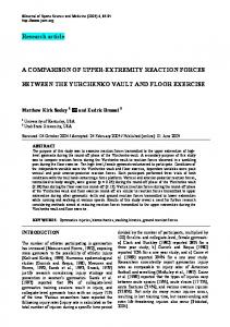
FIGURE 1. Upper extremity model. The model is shown in (A) a lateral view, (B) an anterior view, (C) an anteriomedial view, and (D) a posteriolateral view, demonstrating the degrees of freedom, muscle paths, and selected wrapping surfaces of the model (blue ellipses). Part (A) shows the arm in 45◦ of flexion (90◦ elevation plane) and (B) shows the arm in 45◦ of abduction (0◦ elevation plane).
of the other bones in the model came from outside sources (Primal Pictures, London, UK; Viewpoint Technologies, Orem, Utah), and were scaled in three-dimensions to preserve the anatomical proportions of the average male. Joint Kinematics The model includes 15 degrees of freedom that define the kinematics of the shoulder, elbow, wrist, index finger, and thumb. At the shoulder the three degrees of freedom are elevation plane, thoracohumeral angle (also referred to as elevation angle), and shoulder rotation. The elbow is
defined by elbow flexion and forearm rotation. The two degrees of freedom at the wrist are flexion and deviation. The four degrees of freedom at the index finger are metacarpophalangeal abduction and flexion, and flexion at the distal and proximal interphalangeal joints. The four degrees of freedom for the thumb are carpometacarpal abduction and flexion, metacarpophalangeal flexion, and interphalangeal flexion. The overall motion of the shoulder joint is determined by the collective motion of the shoulder girdle (clavicle, scapula, and humerus) and is described using spherical coordinates. The articulation between the humerus and
A Model of the Upper Extremity
scapula is modeled as a ball-and-socket joint, and the movement of the shoulder girdle is determined by the regression equations described by de Groot and Brand,9 simplified to vary only with thoracohumeral (shoulder elevation) angle. The axis descriptions, degrees of freedom, and order of rotations described by de Groot and Brand9 and used in this model are consistent with those recommended by the International Society of Biomechanics for describing motion at the shoulder.52 The elevation plane degree of freedom describes the orientation of the vertical plane in which the arm elevates relative to the frontal plane. By definition, the 0◦ elevation plane is the plane of shoulder abduction9 and shoulder flexion occurs in the 90◦ elevation plane.9 Neutral elevation angle (0◦ ) for the shoulder is defined when the shaft of the humerus is parallel to the vertical (superior– inferior) axis of the thorax. Neutral (0◦ ) axial rotation is defined by the orientation of the humerus when the shoulder is at neutral elevation angle, the elbow is flexed 90◦ , and the forearm lies in the sagittal plane. The elbow joint rotates about a fixed axis that passes between the center of the trochlear sulcus and the center of the capitulum of the humerus.31 The forearm rotates about an axis that passes through the center of the radial head and the center of the distal ulna. These anatomical points are determined from digitized bone surfaces.36 Elbow flexion is defined from 0◦ (full extension) to 130◦ (flexion) and forearm rotation is defined from 90◦ (pronation) to −90◦ (supination). Neutral position for forearm rotation (0◦ ) is defined when the hand is in the sagittal plane when the shoulder and the wrist are in neutral positions. Wrist motion is distributed between the proximal and distal rows of carpal bones, about axes described by Ruby et al.43 Wrist flexion ranges from −70◦ (extension) to 70◦ (flexion), while deviation ranges from −10◦ (radial) and 25◦ (ulnar). Neutral flexion and deviation is defined when the third metacarpal is aligned with the long axis of the forearm. The axes and center of rotation for the thumb joints are based on descriptions by Hollister et al.19,20 The axes of rotation of the joints in the index finger are determined as the long axis of cylinders fit to the articular surfaces of the metacarpal and phalangeal bones. Neutral position for the joints of the index finger and thumb are defined when the long axes of the phalangeal bones of each digit are aligned with the long axis of the respective metacarpal bone. Muscle Paths Fifty muscles and muscle compartments are included in this model (Table 1). Muscles are represented as multiple compartments when necessary to account for muscles with multiple tendons (e.g., the extensor digitorum communis), distinct heads (e.g., biceps), or wide attachments (e.g., deltoid). Attachment sites of muscles are determined from digitized muscle insertions36 and anatomical descriptions.8
831
Muscle–tendon paths are defined by a set of points and surfaces, attached to the underlying segments, that characterize anatomical constraints (Fig. 1) and allow simulation of the muscle–tendon path over a broad range of joint motion. The path of each muscle in this model is designed to match experimentally measured moment arms3,4,21,30,32,37,39,46 for the joints it crosses. Experimental measurements of shoulder moment arms in cadaveric specimens involve fixing the scapula, and therefore measure the moment arm associated with glenohumeral motion, as opposed to thoracohumeral motion.21,24,30,39 To compare equivalent values, we fixed the scapula in the model and estimated shoulder moment arms as a function of glenohumeral motion. It should be noted that the moment arms for the model with thoracohumeral motion (i.e., when the scapula is allowed to move) differ from the moment arms presented in this paper. Given the complexity of the shoulder mechanism, no experimental source provides moment arm data for all muscles of the shoulder or all degrees of freedom. To concisely present model results and experimental data for 10 muscles and 3 degrees of freedom, we often needed to plot a muscle’s moment arm for one degree of freedom against corresponding data for a second degree of freedom from a different source. For example, the abduction moment arm of middle deltoid was measured in three studies, while its flexion moment arm was only measured in one. To present all of this data, we plotted the different abduction moment arms against the only flexion moment arm available. Muscle Architecture The muscle force-generating characteristics are determined using a Hill-type muscle model53 requiring four muscle parameters: optimal fiber length, peak force, tendon slack length and pennation angle. Parameters are derived from anatomical studies.2,22,25,28,29,35 The parameters implemented for the major elbow muscles are from the same cadaveric specimen as the digitized arm bones; parameters for the other muscles reflect the average reported in the appropriate study (see Table 1). Pennation angle is taken directly from the literature.2,22,25,28,29,35 Optimal fiber length has been reported in the literature using a range of values for optimal sarcomere length (2.2–2.8 µm). For this model, the published optimal fiber lengths are renormalized to an optimal sarcomere length of 2.7 µm, the optimal sarcomere length for mammalian muscle,51 for consistency. Peak force is calculated as the product of physiological cross-sectional area (PCSA) and specific tension. PCSA for each muscle is calculated by dividing muscle volume, as reported in the literature, by the renormalized optimal fiber lengths. For this model, we use a specific tension of 45 N cm−2 for muscles of the forearm and hand22,28,29 and 140 N cm−2 for muscles of the elbow2,35 and shoulder.25 This approach is required in order to represent accurately
TABLE 1. Muscle modeling parameters. Muscle
Shoulder Deltoidc Anterior Middle Posterior Supraspinatusc Infraspinatusc Subscapularisc Teres minorc Teres majorc Pectoralis majorc Clavicular Sternal Ribs Latissimus dorsic Thoracic Lumbar Iliac Coracobrachialisc Elbow Tricepsd Long Lateral Medial Anconeuse Supinatore Bicepsd Long Short Brachialisd Brachioradialisd Major wrist or forearm Extensor carpi radialis longusd Extensor carpi radialis brevisf Extensor carpi ulnarisf Flexor carpi radialisf Flexor carpi ulnarisf Palmaris longusg Pronator teresd Pronator quadratusg Wrist/hand muscles Flexor digitorum superficialisg Digit 5 Digit 4 Digit 3 Digit 2 Flexor digitorum profundusg Digit 5 Digit 4 Digit 3 Digit 2 Extensor digitorum communisg Digit 5 Digit 4 Digit 3 Digit 2 Extensor digiti minimig Extensor indicis propiusg Extensor pollicis longusg Extensor pollicis brevish Flexor pollicis longusg Abductor pollicis longush aFiber
Abbreviation
PCSAa (cm2 )
Peak force (N)
Optimal fiber lengtha (cm)
Tendon slack length (cm)
Pennation (◦ )
mabave (cm)
DELT1 DELT2 DELT3 SUPRA INFRA SUBSCAP TMIN TMAJ
8.2 8.2 1.9 3.5 8.6 9.8 2.5 3.0
1142.6 1142.6 259.9 487.8 1210.8 1377.8 354.3 425.4
9.8 10.8 13.7 6.8 7.6 8.7 7.4 16.2
9.3 11.0 3.8 4.0 3.1 3.3 7.1 2.0
22 15 18 7 19 20 24 16
1.9 2.5 −0.8 −1.0 −2.3 1.9 −1.8 −2.0
PMAJ1 PMAJ2 PMAJ3
2.6 3.7 2.8
364.4 515.4 390.5
14.4 13.8 13.8
0.3 8.9 13.2
17 25 25
0.2 −2.3 −3.2
LAT1 LAT2 LAT3 CORB
2.8 2.8 2.0 1.7
389.1 389.1 281.7 242.5
25.4 23.2 27.9 9.3
12.0 17.7 14.0 9.7
25 19 21 27
−2.2 −3.5 −4.2 −2.0
TRIlong TRIlat TRImed ANC SUP
5.7 4.5 4.5 2.5 3.4
798.5 624.3 624.3 350.0 476.0
13.4 11.4 11.4 2.7 3.3
14.3 9.8 9.1 1.8 2.8
12 9 9 0 0
−2.1 −2.1 −2.1 −1.2 −0.7
BIClong BICshort BRA BRD
4.5 3.1 7.1 1.9
624.3 435.6 987.3 261.3
11.6 13.2 8.6 17.3
27.2 19.2 5.4 13.3
0 0 0 0
3.6 3.6 1.8 5.7
ECRL ECRB ECU FCR FCU PL PT PQ
2.2 2.2 2.1 1.6 2.9 0.6 4.0 1.7
304.9 100.5 93.2 74.0 128.9 26.7 566.2 75.5
8.1 5.9 6.2 6.3 5.1 6.4 4.9 2.8
22.4 22.2 22.8 24.4 26.5 26.9 9.8 0.5
0 9 4 3 12 4 10 10
−1.8 −0.9 2.3 1.4 1.9 2.1 0.8 0.5
FDSL FDSR FDSM FDSI
0.4 1.3 2.0 1.4
16.5 57.9 91.0 61.2
5.2 7.4 7.5 8.4
33.8 32.8 29.5 27.5
5 4 7 6
1.6 1.5 1.5 1.5
FDPL FDPR FDPM FDPI
1.8 1.4 1.8 1.5
79.7 64.1 81.7 68.3
7.5 8.0 8.4 7.5
28.2 28.2 29.3 29.4
8 7 6 7
1.2 1.3 1.3 1.3
EDCL EDCR EDCM EDCI EDM EIP EPL EPB FPL APL
0.3 0.8 0.8 0.4 0.6 0.5 0.9 0.3 1.7 1.3
13.1 34.0 35.3 18.3 25.3 21.7 39.5 14.2 77.2 59.5
6.5 6.3 7.2 7.0 6.8 5.9 5.4 6.8 5.5 7.1
29.7 32.7 33.5 32.2 32.2 18.6 22.1 11.5 19.4 13.0
2 3 3 3 3 6 6 7 7 8
−1.1 −1.4 −1.5 −1.6 1.3 −1.4 −0.9 −2.2 1.6 −2.2
lengths were normalized to an optimal sarcomere length of 2.7 µm. PCSAs were calculated as volume divided by normalized optimal fiber length. bma ave is an average moment arm, and it is needed for calculating measures of the sensitivity of muscle–tendon actuator force generation to a change in joint posture. cFiber length, PCSA, and pennation from Langenderfer et al.25 Experimental PCSA was summed for all compartments. Model PCSA was distributed among muscle compartments to best match experimental values for maximum isometric moments. d Fiber length, PCSA, and pennation from Murray et al.35 eFiber length, PCSA, and pennation from An et al.2 f Fiber length, PCSA, and pennation from Lieber et al.28 g Fiber length, PCSA, and pennation from Lieber et al.29 h Fiber length, PCSA, and pennation from Jacobson et al.22
A Model of the Upper Extremity
the magnitudes of experimental data for maximum isometric moments measured for each of the joints modeled in this study.1,6,10,13,15,40,50 We believe the increase in specific tension relative to values commonly reported for individual muscle fibers or motor units (e.g., 22.5 N cm−2 ) is associated with disuse atrophy, which is likely to occur in the elderly population from which cadaveric specimens are drawn. We postulate that the difference in specific tension between muscles of the forearm and arm arises from patterns of inactivity that influence proximal muscles differently from distal muscles. Buchanan et al.5 have shown that it is often necessary to use different values of specific tension for different muscle groups when scaling muscle PCSA derived from cadaveric specimens. PCSAs for muscles of the shoulder were often reported for multiple compartments.25 In these cases, we sum the reported values across all compartments to estimate a single, total PCSA for each muscle. When it is necessary to use multiple compartments for these muscles in the model, the total PCSA for a given muscle is distributed to best match experimental values for maximum isometric moments. Tendon slack length is not directly measurable, and was selected for each muscle to match operating lengths for muscle fibers35 when available, and to otherwise match muscle active and passive moment measurements from human subjects. Our choices for tendon slack lengths of the elbow and shoulder muscles are significantly correlated to tendon lengths for these muscles estimated from cadaveric studies (r = 0.81, p < 0.01 for the elbow; and r = 0.625, p < 0.02 for the shoulder).25,35 Moment-Generating Capacity The lengths, moment arms, and force-generating capacity of individual muscles are calculated as a function of all of the joints each muscle crosses. The maximum active force and the passive force a muscle produces in a given joint posture are determined based on its PCSA, fiber length, and tendon length. An individual muscle’s momentgenerating capability at a joint depends on joint posture and is calculated as the product of its moment arm and the maximum force it can generate, both of which also vary with joint position. The total moment-generating capability of the muscles that cross a joint is the sum of the moments produced by the individual muscles. We compared experimentally measured moments1,6,10,13,15,40,50 at the joints of interest to the moments estimated by the model to evaluate the performance of the model. The experimental studies measure joint moments using devices that restrain joint motion. In these tests, subjects are instructed to maximally flex or extend against the resistance provided by the device, and the isometric moment they produce is recorded. We assumed maximum activation for muscles in the model when determining maximum isometric moment-generating
833
capability. Every muscle that was able to contribute to the moment we were estimating was included in the estimate (e.g., any muscle that could generate an elbow flexion moment was included in the calculation of total elbow flexion moment). Joint Coupling To test the ability of the model to predict results in conditions that were not used for its design, we simulated two examples of coupling between joints. First, we simulated the relationship between passive finger flexion moment and wrist flexion angle. Second, we simulated the change in supination strength with elbow flexion. We then compared our simulated results to experimental data.23,38 RESULTS Moment arms estimated using the model reflect the primary mechanical functions of the shoulder muscles, as determined by comparisons with cadaveric experimental data.21,24,30,39 To demonstrate this, we compare model estimates and experimental data of the rotator cuff muscles at a joint configuration of 60◦ shoulder abduction and 0◦ of axial rotation (Fig. 2A). The rotation and abduction moment arms of these muscles fall within the range of experimental measurements, although magnitudes vary widely across studies. The primary mechanical actions of the three compartments of the deltoid are not consistent across studies. This is illustrated in the neutral shoulder configuration (Fig. 2B). Our model distributes deltoid’s function of abduction primarily to the middle compartment (cf., DELT2). The flexion and extension moment arms for deltoid estimated in the model were larger than the one source of experimental data24 for this plane of action. The flexion and extension moment arms for the latissimus dorsi (LAT), pectoralis major (PEC), and teres major (TMAJ) muscles (Fig. 2C) are also larger than the one source of experimental data.24 Adduction moment arms for these muscles are smaller in the model. The moment arms estimated using the model for the elbow and the wrist are comparable to moment arms measured experimentally. To demonstrate this, we compare model estimates and experimental data at a joint configuration of 90◦ elbow flexion, neutral forearm and neutral wrist (Fig. 3). In these postures, the average difference was 0.26 cm (SD = 0.45 cm). The largest difference between measured and estimated moment arms was 3.18 cm for the brachioradialis (BRD) elbow flexion moment arm when compared to the measured moment arm for the female specimen in the Murray et al.37 study (Fig. 3A). However, the model estimate was only 0.35 cm smaller than the moment arm measured in the cadaveric specimen from which the elbow model was developed.36 The smallest difference observed was 0.0014 cm for the wrist deviation moment arm for the fourth digit compartment of flexor digitorum
834
HOLZBAUR et al.
profundus (FDPR) when compared to the data from Brand and Hollister4 (Fig. 3B). The upper extremity model accurately reflects the relative moment-generating capacity of the muscles that cross the shoulder, elbow, and wrist. At the shoulder, the total joint moment-generating capability estimated using the model corresponds with experimental measurements of maximum isometric moments13,15,40,50 that indicate, on average, the shoulder extensors are stronger than flexors, the adductors are stronger than the abductors, and internal rotators are stronger than external rotators. Similarly, the model reflects the trend in the data suggesting that average flexion and extension moments are larger than abduction and adduction moments and internal and external rotation moments. The total moment-generating capacity of the elbow flexors is greater than the elbow extensors, as observed experimentally.1,6 Also, isometric strength in elbow flexion and extension exceeds forearm rotation.15 Finally, like experimental data,10 the model generates greater wrist moments for flexion than extension, and for radial deviation than ulnar deviation. The maximum isometric joint moments estimated using the model represent many features observed in experimental data. The steady decrease in shoulder flexion strength and increase in shoulder extension strength with shoulder flexion is represented by the model (Fig. 4A). Flexion moment-generating capacity in the model decreases with shoulder flexion at the same rate as in the literature,15,40,50 decreasing 34 and 30 Nm, respectively, over 90◦ of shoulder flexion (Fig. 4A). The model reproduces both the decrease in shoulder abduction strength and increase in shoulder adduction strength with increasing shoulder abduction angle that has been observed experimentally15,40 (Fig. 4B). Maximal isometric internal rotation moment estimated by the model shows the steady decrease in internal rotation moment found by Engin and Kaleps13 and Otis et al.40 External rotation moment peaks at approximately 50◦ rotation,
← FIGURE 2. Muscle moment arms at the shoulder for (A) the rotator cuff, (B) the three compartments of deltoid, and (C) other shoulder muscles, including teres major (TMAJ), latissimus dorsi (LAT), and pectoralis major (PEC). The model estimates are shown as the black diamonds and compared to experimental data from Otis et al.,39 Liu et al.,30 Hughes et al.,21 and Kuechle et al.24 In (A), rotation moment arms were not available for the rotator cuff in the Liu et al.,30 Hughes et al.,21 or Kuechle et al.24 studies. The abduction moment arms for those data were plotted at the average of the rotation moment arms from the Otis et al.,39 study. In (B), flexion moment arms were not available for the deltoid in the Otis et al.39 and Liu et al.30 studies. The abduction moment arms for those data were plotted at the flexion moment arm values from the Kuechle et al.24 study. In (A), shoulder rotation and abduction moment arms were calculated with the shoulder in 60◦ of abduction and 0◦ of axial rotation. In (B) and (C), shoulder flexion and abduction moment arms were calculated with the arm in a neutral configuration.
A Model of the Upper Extremity
835
FIGURE 3. Muscle moment arms at the (A) elbow and (B) wrist. The model estimates are shown as the black diamonds and compared to experimental data from male and female specimens from Murray et al.,37 Murray et al.,36 Loren et al.,32 and Brand and Hollister.4 In (A), forearm rotation moment arms were not available for the Murray et al.36 study. The flexion moment arms for those data were plotted at the average of the forearm rotation moment arms from the Murray et al.37 study. All compartments of triceps (TRI) have the same moment arms at the elbow. All compartments of biceps (BIC) have the same moment arms at the elbow. Moment arms reported from Murray et al.36 are for the same cadaveric specimen as the digitized bones used in the model. Elbow flexion and forearm rotation moment arms were calculated with the elbow in 90◦ flexion and the forearm in neutral rotation. Wrist deviation and flexion moment arms were calculated with the wrist in a neutral configuration.
similar to Engin and Kaleps,13 with a more pronounced increase in external rotation moment at peak (Fig. 4C). The peak isometric elbow flexion moment estimated using the model (103 Nm) was larger than the peak moments reported in the literature (∼77 Nm)1,6 (Fig. 5A). The peak elbow extension moment estimated using the model was approximately 43 Nm, lower than the 52 Nm in the literature.1,6 Moment estimates for the forearm capture the increase in supination strength and decrease in pronation
strength as the forearm is pronated, as well as capturing the overall magnitude of forearm strength found in the experimental literature15 (Fig. 5B). The peak experimental wrist flexion and extension moments were 11 and 6.5 Nm, respectively,10 and the model estimates the peaks to be 10.7 and 7.3 Nm, respectively (Fig. 6A). Both experimental results10 and model predictions exhibit peak wrist flexion moment as the wrist moves into flexion (between 20 and 40◦ of flexion) and relatively constant extension moments.
FIGURE 4. Maximum isometric moments generated by (A) shoulder flexors and extensors versus shoulder flexion, (B) shoulder abductors and adductors versus shoulder abduction, and (C) shoulder internal and external rotators versus shoulder rotation. The model estimates are shown as the heavy solid curves and compared to experimental data from Otis et al.,40 Winters et al.,50 Garner and Pandy,15 and Engin and Kaleps.13 Shoulder flexion, extension, abduction, and adduction moments were calculated with the elbow in 60◦ flexion and all other degrees of freedom in a neutral position. Shoulder rotation moments were calculated with the elbow in 60◦ flexion, the shoulder in 60◦ of abduction, and all other degrees of freedom in a neutral position. Shoulder flexion, abduction, and internal rotation are positive values.
836
HOLZBAUR et al.
FIGURE 5. Maximum isometric moments generated by (A) elbow flexors and extensors versus elbow flexion angle, and (B) forearm pronators and supinators versus pronation angle. The model estimates are shown as the heavy solid curves and compared to experimental data from Buchanan et al.,6 Garner and Pandy,15 and Amis et al.1 Values for elbow flexion moment are calculated with the shoulder, forearm, and wrist in the neutral position (see text for details). Maximum pronation moments were calculated with the elbow in 90◦ of flexion, and all other degrees of freedom in a neutral position. Elbow flexion and forearm pronation are positive values.
The model represents the decrease in both ulnar and radial deviation strength as the wrist ulnarly deviates as seen in the experimental literature10 (Fig. 6B). The passive flexion moment at the index finger increases substantially with finger extension (Fig. 6C).
The model estimates a marked increase in the passive flexion moment at the second metacarpophalangeal joint with extension of the wrist (Fig. 7A). The model estimates the moment-generating capacity of the supinators with the arm in neutral rotation to be 8 Nm at 0◦ elbow
FIGURE 6. Maximum isometric moments generated by (A) wrist flexors and extensors versus wrist flexion angle, and (B) wrist radial and ulnar deviators versus deviation angle, and (C) passive moments generated by the extrinsic hand muscles at the second metacarpophalangeal joint versus second metacarpophalangeal joint flexion. The model estimates are shown as the heavy solid curves and compared to experimental data from Delp et al.10 (A and B) and Knutson et al.23 (C). Wrist moments were calculated with the elbow in 90◦ of flexion, and all other degrees of freedom in a neutral position. Finger moments were calculated with all degrees of freedom in a neutral position. Wrist flexion, ulnar deviation, and finger flexion are positive values.
A Model of the Upper Extremity
837
FIGURE 7. Joint coupling shown by (A) the passive moment about the second metacarpophalangeal (MCP) joint versus wrist flexion angle and (B) the maximum isometric moment generated by the forearm supinators versus elbow flexion angle. The model estimates are shown as the heavy solid curves and compared to experimental data from Knutson et al.23 and O’Sullivan and Gallwey.38 Standard deviations from the experimental data are shaded in grey. Wrist flexion, finger flexion, and pronation are positive values.
flexion increasing to a peak of 17 Nm at 94◦ elbow flexion (Fig. 7B). DISCUSSION The goal of this study was to produce a threedimensional model of the upper extremity including muscles and joints from the shoulder to fingertip and to evaluate this model using comparisons to experimentally measured moment arms and maximum isometric joint moments. Our model characterizes the mechanical actions of the muscles of the upper extremity, as determined by comparisons with experimentally measured moment arms. The magnitudes of moment arms matched well with published literature at the elbow and wrist. While there were wide variations in magnitudes in the experimental data at the shoulder, the model captured the multi-faceted function of these complex muscles. For each joint, the model demonstrated substantial agreement with published data describing isometric joint moments. Previous studies have described three-dimensional musculoskeletal models of the upper extremity. Excellent models of individual joints or segments of the upper extremity, such as the shoulder,48 wrist,16 hand,44 or thumb,47 have been developed and are useful for examining the biomechanics of those joints in isolation. However, the biome-
chanics of a given joint in the upper extremity can depend on the posture of adjacent joints. For example, we illustrated how this multi-joint model captures the increase in passive finger flexion that occurs with wrist extension23 and the increase in supination strength with elbow flexion38 (Fig. 7). The coupling effects demonstrate predictive capabilities of the model, as joint coupling was not assessed during model development. Others have also created multi-joint models of the upper extremity. Lemay and Crago26 presented an integrated model of the elbow, forearm, and wrist with muscle parameters based on anatomical data from the literature. The result was a model that met several of the criteria outlined in the introduction, including deriving muscle parameters from experimental data, incorporating all of the muscles in the region of interest, and representing coupling. Subsequently, more complete anatomical studies that describe the force-generating parameters of muscle and muscle moment arms have become available.25,35 We incorporated these newly available anatomical data. Garner and Pandy15 created a model that incorporates the shoulder, elbow, forearm, and wrist, contributing a model that accurately represents many of the features of experimentally measured maximal isometric moments and is able to capture joint coupling. However, muscles of the hand were not included. We included the extrinsic hand muscles (e.g., flexor digitorum
838
HOLZBAUR et al.
superficialis) in the current model because these muscles are capable of generating substantial moments about the wrist16 and are important to consider when evaluating wrist function. An important criterion for our modeling efforts was to derive muscle force-generating parameters from experimental studies. We believe that this approach ultimately strengthens the resulting model. For example, optimal fiber length and moment arm are needed to understand muscle excursion over the joint range of motion.16 By relying on optimal lengths determined by detailed studies of muscle architecture, we are confident that this parameter reflects the overall excursion capacity of each muscle. There are other approaches to muscle parameter selection. For example, Garner and Pandy15 implemented an optimization algorithm to choose muscle parameters from within pre-defined physiological limits. While this approach may be effective and efficient, it also has the potential to introduce unknown error into all of the parameters in the system. By focusing on experimentally derived parameters, we have identified specific areas for which either quantitative measurements essentially do not exist (e.g., tendon slack length), current methods are not representative (e.g., scaling PCSA from cadaveric specimens to isometric moment-generating capacity of healthy adults), or anatomical data collection requires greater coordination with model design (e.g., how to distribute PCSA for a multi-compartment muscle, or collecting all of the muscle parameters in a single study). We feel that our approach constrains uncertainty in parameter estimation to specific, defined areas, which can assist users when interpreting simulation results as well as identify future directions for experimental research. We evaluated our parameter selection based on a sensitivity analysis performed previously for a model of the lower extremity12 that incorporates the same type of muscle model and moment calculation. We focused on tendon slack length because it was the parameter with the most uncertainty and the least experimental data on which to base our choices. The previous analysis showed that muscles with high ratios between tendon slack length and average moment arm (lst /maave ) and low ratios between optimal fiber length and average moment arm (lom /maave ) are most sensitive to the choice of tendon slack length. In the current upper extremity model, we observed that the muscles whose primary function is at the wrist tend to have much higher lst /maave ratios (average = 17.4) than the muscles that actuate the elbow (average = 4.4) and shoulder (average = 3.6). Similarly, lom /maave ratios tended to be lowest for the wrist muscles. These observations indicate that the force-generating capacity of the wrist muscles are the most sensitive of the upper extremity muscles to our parameter estimation approach. While we acknowledge this limitation, we are confident in our parameter selection of tendon slack length for the wrist muscles given the high quality of experimental data for the other force generating
parameters, moment arms, and joint moments, which were used to guide the selection of tendon slack length. With regard to our choice to scale the PCSAs of muscles of the forearm differently from muscles of the shoulder and elbow, it is important to note that the relative strength of the pronator teres and extensor carpi radialis longus may be large relative to the strength of the other forearm muscles in the model. We chose to scale these muscles with the other elbow muscles from the same data set collected on the same specimens.35 Several limitations must be considered when using the musculoskeletal model we describe. We have simplified the motion of the shoulder girdle. We have constrained the motion of the clavicle and the scapula to depend on the motion of the humerus. Measuring the motions of the scapula and clavicle is challenging, but measuring the motion of the humerus relative to the thorax is not. We believe that explicitly constraining the kinematics of the clavicle and scapula based on typical motion will be preferred for most users. The motions of the clavicle and the scapula in our model vary only with humeral elevation. The kinematic data on which we based our model9 shows that motion of the scapula and clavicle also varied with the plane of elevation. This simplification will influence moment arms of the muscles that cross from the torso to the humerus. Because there is no moment arm data for a shoulder with a moving scapula, it is difficult to quantify the degree of this effect. In addition, the de Groot and Brand9 model, which was the basis of our shoulder kinematics, was not tested for high-speed or high load motions and may be less accurate for such conditions. We have provided tests of the model’s accuracy in estimating the maximum active isometric moments at the shoulder, elbow, forearm, and wrist, and passive moments at the metacarpophalangeal joint of the index finger. We have not provided active tests for the index finger and thumb. This model does not include representations of the intrinsic muscles of the hand; therefore, we would not expect the moments at these joints to accurately reflect moment magnitudes at these joints. Kinematic representations of the joints of these fingers and inclusion of the extrinsic muscles are important for a wrist model and for examining how hand function changes in different wrist positions. Muscles are assumed to consist of fibers of equal length. However, muscles may contain fibers of varying length, and these fibers have different paths due to the threedimensional nature of muscle. The assumption of equal fiber length within a muscle could contribute to the greater change in moment with joint angle that can be seen in the model estimates of shoulder extension and external rotation, and elbow flexion. In addition, muscles with wide attachments may have fibers with divergent paths. To address this issue, when necessary, several muscle paths were used to model a single muscle (e.g., deltoid). We attempted to use one path per muscle compartment. This was an attempt to
A Model of the Upper Extremity
limit the amount of error generated by simplifying muscle structure. The model we have described represents an adult male of average size with muscle parameters based on the average of data available from anatomical studies. Subject-specific models using an individual’s muscle parameters and muscle paths would be useful for designing subject-specific surgical plans. A generic model such as the one we describe is useful for a broad range of studies, including simulations of upper limb surgery, calculation of limb impedance, and calculation of end-point forces at a fingertip generated by individual muscles. Future directions in the development of this model will focus on defining scaling rules to tailor the model to more accurately represent individual subjects. We realize that a single model is unlikely to be ideally suited to all studies of upper extremity biomechanics. However, we have integrated the best available experimental data to create a model that can form the basis for a wide range of studies. We intend for the model to be used not only in its complete form, but also to be modified to use isolated sections or specific muscles. Modification to represent individual subjects, to represent different surgical conditions, to include additional muscles (e.g. hand intrinsics), or to represent pathological or more complex joint kinematics is desirable. ACKNOWLEDGMENTS We would like to acknowledge funding from the Whitaker Foundation, Medtronic Foundation Stanford Graduate Fellowship, the NIH (#U54 GM072970), and the Rehabilitation Research and Development Service of the Department of Veterans Affairs (#B2785R). We would also like to acknowledge Richard Hughes, Joseph Langenderfer, and Richard Lieber for their helpful discussion regarding integrating muscle architecture data into a musculoskeletal model. REFERENCES 1
Amis, A. A., D. Dowson, and V. Wright. Analysis of elbow forces due to high-speed forearm movements. J. Biomech. 13:825–831, 1980. 2 An, K. N., F. C. Hui, B. F. Morrey, R. L. Linscheid, and E. Y. Chao. Muscles across the elbow joint: A biomechanical analysis. J. Biomech. 14:659–669, 1981. 3 An, K. N., Y. Ueba, E. Y. Chao, W. P. Cooney, and R. L. Linscheid Tendon excursion and moment arm of index finger muscles. J. Biomech. 16:419–425, 1983. 4 Brand, P. W., and A. Hollister. Clinical Mechanics of the Hand, 2nd ed. St. Louis, MO: Mosby-Year Book, 1993, p. 386. 5 Buchanan, T. S. Evidence that maximum muscle stress is not a constant: Differences in specific tension in elbow flexors and extensors. Med. Eng. Phys. 17:529–536, 1995. 6 Buchanan, T. S., S. L. Delp, and J. A. Solbeck. Muscular resistance to varus and valgus loads at the elbow. J. Biomech. Eng. 120:634–639, 1998.
7
839
Buchanan, T. S., and D. A. Shreeve. An evaluation of optimization techniques for the prediction of muscle activation patterns during isometric tasks. J. Biomech. Eng. 118:565–574, 1996. 8 Dalley, A. F. I., and K. L. Moore. Clinically Oriented Anatomy. Baltimore, MD: Lippincott Williams and Wilkins, 1999. 9 de Groot, J. H., and R. Brand. A three-dimensional regression model of the shoulder rhythm. Clin. Biomech. 16:735–743, 2001. 10 Delp, S. L., A. E. Grierson, and T. S. Buchanan. Maximum isometric moments generated by the wrist muscles in flexionextension and radial-ulnar deviation. J. Biomech. 29:1371–1375, 1996. 11 Delp, S. L., and J. P. Loan. A graphics-based software system to develop and analyze models of musculoskeletal structures. Comput. Biol. Med. 25:21–34, 1995. 12 Delp, S. L., J. P. Loan, M. G. Hoy, F. E. Zajac, E. L. Topp, and J. M. Rosen. An interactive graphics-based model of the lower extremity to study orthopaedic surgical procedures. IEEE Trans. Biomed. Eng. 37:757–767, 1990. 13 Engin, A. E., and I. Kaleps. Active muscle torques about longbone axes of major human joints. Aviat. Space Environ. Med. 51:551–555, 1980. 14 Fowler, N. K., and A. C. Nicol. A biomechanical analysis of the rheumatoid index finger after joint arthroplasty. Clin. Biomech. 17:400–405, 2002. 15 Garner, B. A., and M. G. Pandy. Musculoskeletal model of the upper limb based on the visible human male dataset. Comput. Methods Biomech. Biomed. Eng. 4:93–126, 2001. 16 Gonzalez, R. V., T. S. Buchanan, and S. L. Delp. How muscle architecture and moment arms affect wrist flexion-extension moments. J. Biomech. 30:705–712, 1997. 17 Gordon, C. C., T. Churchill, C. E. Clauser, B. Bradtmiller, J. T. McConville, I. Tebbets, and R. A. Walker. 1988 Anthropometric Survey of U.S. Army Personnel: Methods and Summary Statistics. Natick, MA: United States Army Natick Research, Development and Engineering Center, 1989. 18 Herrmann, A. M., and S. L. Delp. Moment arm and forcegenerating capacity of the extensor carpi ulnaris after transfer to the extensor carpi radialis brevis. J. Hand Surg. [Am.] 24:1083– 1090, 1999. 19 Hollister, A., W. L. Buford, L. M. Myers, D. J. Giurintano, and A. Novick. The axes of rotation of the thumb carpometacarpal joint. J. Orthop. Res. 10:454–460, 1992. 20 Hollister, A., D. J. Giurintano, W. L. Buford, L. M. Myers, and A. Novick. The axes of rotation of the thumb interphalangeal and metacarpophalangeal joints. Clin. Orthop. 188–193, 1995. 21 Hughes, R. E., G. Niebur, J. Liu, and K. N. An. Comparison of two methods for computing abduction moment arms of the rotator cuff. J. Biomech. 31:157–160, 1998. 22 Jacobson, M. D., R. Raab, B. M. Fazeli, R. A. Abrams, M. J. Botte, and R. L. Lieber. Architectural design of the human intrinsic hand muscles. J. Hand Surg. [Am.] 17:804–809, 1992. 23 Knutson, J. S., K. L. Kilgore, J. M. Mansour, and P. E. Crago. Intrinsic and extrinsic contributions to the passive moment at the metacarpophalangeal joint. J. Biomech. 33:1675–1681, 2000. 24 Kuechle, D. K., S. R. Newman, E. Itoi, B. F. Morrey, and K. N. An. Shoulder muscle moment arms during horizontal flexion and elevation. J. Shoulder Elbow Surg. 6:429–439, 1997. 25 Langenderfer, J., S. A. Jerabek, V. B. Thangamani, J. E. Kuhn, and R. E. Hughes. Musculoskeletal parameters of muscles crossing the shoulder and elbow and the effect of sarcomere length sample size on estimation of optimal muscle length. Clin. Biomech. 19:664–670, 2004. 26 Lemay, M. A., and P. E. Crago. A dynamic model for simulating movements of the elbow, forearm, an wrist. J. Biomech. 29:1319–1330, 1996.
840 27
HOLZBAUR et al.
Lemay, M. A., P. E. Crago, and M. W. Keith. Restoration of pronosupination control by FNS in tetraplegia—experimental and biomechanical evaluation of feasibility. J. Biomech. 29:435– 442, 1996. 28 Lieber, R. L., B. M. Fazeli, and M. J. Botte. Architecture of selected wrist flexor and extensor muscles. J. Hand Surg. [Am.] 15:244–250, 1990. 29 Lieber, R. L., M. D. Jacobson, B. M. Fazeli, R. A. Abrams, and M. J. Botte. Architecture of selected muscles of the arm and forearm: Anatomy and implications for tendon transfer. J. Hand Surg. [Am.] 17:787–798, 1992. 30 Liu, J., R. E. Hughes, W. P. Smutz, G. Niebur, and K. Nan-An. Roles of deltoid and rotator cuff muscles in shoulder elevation. Clin. Biomech. 12:32–38, 1997. 31 London, J. T. Kinematics of the elbow. J. Bone Joint Surg. Am. 63:529–535, 1981. 32 Loren, G. J., S. D. Shoemaker, T. J. Burkholder, M. D. Jacobson, J. Friden, and R. L. Lieber. Human wrist motors: Biomechanical design and application to tendon transfers. J. Biomech. 29:331– 342, 1996. 33 Magermans, D. J., E. K. Chadwick, H. E. Veeger, P. M. Rozing, and F. C. van der Helm. Effectiveness of tendon transfers for massive rotator cuff tears: A simulation study. Clin. Biomech. 19:116–122, 2004. 34 Murray, W. M., A. M. Bryden, K. L. Kilgore, and M. W. Keith. The influence of elbow position on the range of motion of the wrist following transfer of the brachioradialis to the extensor carpi radialis brevis tendon. J. Bone Joint Surg. Am. 84-A:2203– 2210, 2002. 35 Murray, W. M., T. S. Buchanan, and S. L. Delp. The isometric functional capacity of muscles that cross the elbow. J. Biomech. 33:943–952, 2000. 36 Murray, W. M., T. S. Buchanan, and S. L. Delp. Scaling of peak moment arms of elbow muscles with upper extremity bone dimensions. J. Biomech. 35:19–26, 2002. 37 Murray, W. M., S. L. Delp, and T. S. Buchanan. Variation of muscle moment arms with elbow and forearm position. J. Biomech. 28:513–525, 1995. 38 O’Sullivan, L. W., and T. J. Gallwey. Upper-limb surface electromyography at maximum supination and pronation torques: The effect of elbow and forearm angle. J. Electromyogr. Kinesiol. 12:275–285, 2002. 39 Otis, J. C., C. C. Jiang, T. L. Wickiewicz, M. G. Peterson, R. F. Warren, and T. J. Santner. Changes in the moment arms of the rotator cuff and deltoid muscles with abduction and rotation. J. Bone Joint Surg. Am. 76:667–676, 1994.
40
Otis, J. C., R. F. Warren, S. I. Backus, T. J. Santner, and J. D. Mabrey. Torque production in the shoulder of the normal young adult male. The interaction of function, dominance, joint angle, and angular velocity. Am. J. Sports Med. 18:119–123, 1990. 41 Piazza, S. J., and S. L. Delp. Three-dimensional dynamic simulation of total knee replacement motion during a step-up task. J. Biomech. Eng. 123:599–606, 2001. 42 Rancourt, D., and N. Hogan. Stability in force-production tasks. J. Mot. Behav. 33:193–204, 2001. 43 Ruby, L. K., W. P. Cooney, 3rd, K. N. An, R. L. Linscheid, and E. Y. Chao. Relative motion of selected carpal bones: A kinematic analysis of the normal wrist. J. Hand Surg. [Am.] 13:1–10, 1988. 44 Sancho-Bru, J. L., A. Perez-Gonzalez, M. Vergara, and D. J. Giurintano. A 3D biomechanical model of the hand for power grip. J. Biomech. Eng. 125:78–83, 2003. 45 Saul, K. R., W. M. Murray, V. R. Hentz, and S. L. Delp. Biomechanics of the Steindler flexorplasty surgery: A computer simulation study. J. Hand Surg. [Am.] 28:979–986, 2003. 46 Smutz, W. P., A. Kongsayreepong, R. E. Hughes, G. Niebur, W. P. Cooney, and K. N. An. Mechanical advantage of the thumb muscles. J. Biomech. 31:565–570, 1998. 47 Valero-Cuevas, F. J., M. E. Johanson, and J. D. Towles. Towards a realistic biomechanical model of the thumb: The choice of kinematic description may be more critical than the solution method or the variability/uncertainty of musculoskeletal parameters. J. Biomech. 36:1019–1030, 2003. 48 van der Helm, F. C. A finite element musculoskeletal model of the shoulder mechanism. J. Biomech. 27:551–569, 1994. 49 Winter, D. Biomechanics and Motor Control of Human Movement, 2nd ed. New York: Wiley, 1990. 50 Winters, J. M., and D. G. Kleweno. Effect of initial upper-limb alignment on muscle contributions to isometric strength curves. J. Biomech. 26:143–153, 1993. 51 Woledge, R. C., N. A. Curtin, and E. Homsher. Energetic aspects of muscle contraction. Monogr. Physiol. Soc. 41:1–357, 1985. 52 Wu, G., F. C. T. van der Helm, H. E. J. (DirkJan) Veeger, M. Makhsous, P. Van Roy, C. Anglin, J. Nagels, A. R. Karduna, K. McQuade, and X. Wang. ISB recommendation on definitions of joint coordinate systems of various joints for the reporting of human joint motion. Part II. Shoulder, elbow, wrist and hand. J. Biomech. 38:981–992, 2005. 53 Zajac, F. E. Muscle and tendon: Properties, models, scaling, and application to biomechanics and motor control. Crit. Rev. Biomed. Eng. 17:359–411, 1989.