A Modelling Proposal for Aspect-Oriented Software Architectures Jennifer Pérez Department of Information Systems and Computation, UPV
[email protected]
Elena Navarro Department of Computer Science, UCLM
[email protected]
Abstract Aspect-Oriented Programming (AOP) has emerged in recent years as a new paradigm for software development. PRISMA is an approach for developing complex and large software systems. It combines the Aspect-Oriented Software Development (AOSD) and the Component-Based Software Development (CBSD) in an elegant and novel way achieving a better management of crosscutting-concerns and software reusability. PRISMA approach proposes the separation of concerns from the very beginning of the software life-cycle in order to introduce them as reusable aspects of software architecture. PRISMA provides a framework to guide the development of complex and large software systems. The framework is composed by a modelling tool, a .NET middleware, and a compiler to automatically generate the application source code. In this paper, we present the modeling tool of the PRISMA framework and how it supports the reuse and maintenance improvements of the PRISMA model and its Aspect-Oriented Description Language (AOSD). We illustrate our proposal and modelling tool using a real-life case, the TeachMover robot. 1. Introduction The complexity of current software systems and the fact that their non-functional requirements have become very relevant for the end-user are to challenges to be faced on every software development. Two new approaches of software development have emerged to overcome these needs: Component-Based Software Development (CBSD) [38] and Aspect-Oriented Software Development (AOSD) [5]. On the one hand, CBSD reduces the complexity of software development and improves its maintenance by increasing software reuse. CBSD decomposes the system into reusable entities called components. By extension, this advantage is provided by software architectures [11] due to the fact that architectural models are constructed using components. As a result, software architectures have emerged as a solution for design and development processes of complex software systems.
Patricio Letelier Isidro Ramos Department of Department of Information Systems Information Systems and Computation, UPV and Computation, UPV
[email protected] [email protected]
On the other hand, AOSD improves the quality of software and accurately satisfies the needs of the end-user giving equal importance to functional and non-functional requirements from the first stages of the software lifecycle. AOSD also reduces the complexity of software development and improves its maintenance by increasing the reusability of software. This approach allows the separation of concerns by modularizing crosscuttingconcerns in a separate entity called aspect. PRISMA is an approach that combines the CBSD and the AOSD to model software architectures. PRISMA provides the advantages of both approaches by means of its model and its Aspect-Oriented Architecture Description Language (AOADL). PRISMA takes advantage of the aspect-oriented approach to achieve more reusable and maintainable software architectures [33]. In this sense, it specifies the different concerns (safety, distribution, coordination, etc.) that crosscut a software system as aspects; these aspects are used to define PRISMA architectural elements (component, connector). The PRISMA AOADL has a graphical notation that is based on a UML profile [26]. In this paper, we present how PRISMA reduces the complexity in software development by providing a graphical notation and a modelling tool to support more intuitive and friendly software architecture modelling. Moreover, we show how the reusability of aspects and components is supported by the modelling tool and facilitates the development of complex architectures. The structure of the paper is the following: Section 2 presents the tele-operation domain and the TeachMover case study which is used through out the paper. Section 3 details the advantages that the PRISMA model obtains from the aspect-oriented approach. Section 4 presents how PRISMA allows the graphical modelling of software architectures taking advantage of its maintenance and reuse improvements; the graphical notation of the PRISMA AOADL, part of PRISMA UML profile and their implementation in a graphical editor are explained in detail. Section 5 compares related works on aspectoriented software architectures. Finally, conclusions and further work are presented in section 6.
2. Tele-operation Systems: The TeachMover
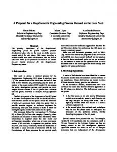
Robot There are many kinds of software systems whose large and complex software architectures must be reusable and maintainable. An example of software systems of this kind are the so-called tele-operation systems. Teleoperation systems perform risky activities, substituting human operators in dangerous areas. They are usually robots that are controlled by a human operator from a safe area. Specifically, we are working on the development of a tele-operation robot called TeachMover [9], we designed and implemented the PRISMA architecture of the TeachMover robot [39] (shown in Figure 1). We are going to illustrate the advantages of the PRISMA model and the facilities of the graphical editor using the TeachMover robot case study.
system called Simple Unit Controller (SUC) (see Figure 2). As a result, a SUC is a complex component (system) that manages the basic interactions of the joints of the TeachMover. Due to the complexity of this software system, in this paper, we only focus on the low levels of the hierarchical architecture of the TeachMover robot, i.e, on SUC. For more details about the specification see [32].
Figure 2. The external view of the SUC system
Figure 3. The internal view of the SUC system
3. A PRISMA overview
Figure 1. The TeachMover robot
The TeachMover is formed by a set of joints that permit the movement of the robot. These joints are: Base, Shoulder, Elbow and Wrist. In addition, it has a Tool to perform different tasks. In this case, the Tool is a gripper whose open and close actions allow the robot to pick up objects. The functionality of the TeachMover robot is to move itself by means of half-steps or inverse cinematics (moving to a specific point in the space) at a specific speed. This functionality, together with the functionality of the Tool, allows the robot to move objects from an initial position to a final one. The movements of the robot are ordered by an operator from a computer. In addition, safety directives require that the TeachMover movements be checked in order to control that they are safe for the robot, the operator, and the environment which surrounds them. The TeachMover architecture has a lot of components, connectors and their interactions at different levels of abstraction. The lowest level of the robot architecture has sensors and actuators as basic components. They are the software components that are communicated with the hardware joints of the robot. Actuators send commands to a joint to be performed; sensors are listeners of the results of the command executions. An actuator and a sensor are coordinated by means of a connector (see Figure 3). These three architectural elements (actuator, sensor and SUCconnector) (see Figure 3) are encapsulated inside a
The main effort in the AOSD has been made at the implementation level, from which Aspect-Oriented Programming (AOP) has emerged as a new paradigm of software development. The AOSD was introduced in [15], where aspects were defined as properties that crosscut the software system, thereby achieving a reduction in tangled code. The concept of aspect, its advantages, and how it is weaved with the class (kernel) by means of the pointcuts, joinpoints and advice methods (after, before, around) are clear at the implementation level. However, not much work has been done concerning aspects at an architectural level. As a result, there is no consensus about what is an aspect in a software architecture and how aspects should weaved architectural elements.
3.1. PRISMA Approach PRISMA approach has a formal model that uses AOSD principles to describe software architectures. A PRISMA aspect represents a specific concern for the software architecture under development. In PRISMA, from the very beginning of the specification all the behaviour is modularized in aspects, so that they can be imported by one or more architectural elements in order to properly manage crosscutting-concerns. A PRISMA architectural element (components and connectors) is formed by a set of aspects that describe it from the different concerns of the architecture. The kind of aspect (safety, coordination, distribution, etc.) that forms an architectural element depends on the concerns of the software system that we are specifying. In the case of the TeachMover software system, the concerns that crosscut the SUC system are the following:
− Functional aspect: This kind of aspect is necessary to specify the computation of the joints and Tool of the Teachmover system. − Coordination aspect: This kind of aspect is necessary to specify the synchronization between the different architectural elements that form the TeachMover architecture. − Safety aspect: This kind of aspect is necessary because safety properties are extremely important to establish a safety control of the robot movements. The movements must be safe for the robot itself and for the rest of the elements of its environment. Each architectural element of a PRISMA model is formed by a set of aspects that describe it from the different concerns of the architecture. Architectural elements can be analyzed from two different views: internal (white box view) and external (black box view). The white box view shows an architectural element as a prism, each side of which is an aspect of this architectural element. The black box view encapsulates the architectural element functionality and publishes a set of services that it offers to other architectural elements. There are three kinds of architectural elements: components, connectors and systems. All of them share the fact that they are formed by a set of aspects and their synchronization relationships (weavings). − A component is an architectural element that captures the functionality of the system and does not act as a coordinator among other elements. It is formed by an identifier, a set of aspects together with their synchronization relationships (aspect weavings), and one or more ports. These ports represent the interaction points among architectural elements and are typed by interfaces. An interface publishes a set of services that can be required or provided by the component. − A connector is an architectural element that acts as a coordinator among components. It is formed by an identifier, a set of aspects together with their synchronization relationships (aspect weavings), and one or more ports. These ports represent interaction points among architectural elements and are typed by interfaces. An interface publishes a set of services that can be required or provided by the connector. − A system is a complex component that includes a set of architectural elements (connectors, components, systems) that are connected among them and a set of ports to publish the services required or provided by the system. A system definition must specify the connection relationships (attachments) and the composition relationships (bindings) among the architectural elements that it includes. Attachments establish the connection among ports of components and roles of connectors, whereas bindings define the composition between the ports of the system and the
ports of the architectural elements which the system contains.
3.2. PRISMA AOADL PRISMA has an AODL to define reusable architectural elements and aspects; as well as specific architectures by creating and interconnecting the instances of the defined reusable types. It is based on the OASIS language [18] in order to define its semantics in a formal way and to preserve its main advantages, i.e., the validation and the verification of architectural models and the automatic generation code. A full description of the language is out of the scope of this paper. Here, we are going to focus on how PRISMA takes advantage of the aspect specification. 3.2.1. Reusing Aspects PRISMA aspects are first-order citizens of the language and are specified without considering which architectural elements will import them in the future. When an aspect is defined, it is stored in the PRISMA repository to be reused by different architectural elements of the same or of different architectural models. Table 1. The SMotion safety aspect Safety Aspect SMotion Attributes Constant minimum, maximum: integer, NOT NULL; Services begin( input InitialMinimum: integer, input InitialMaximum: integer);… … in check(input Degrees: integer, output Secure: boolean);… … in controlSpeed(input CurrentSpeed: integer, output Secure: boolean);… … Operations transaction DANGEROUSCHECKING(input Degrees: integer, input CurrentSpeed: integer, output Secure: boolean): … … Protocol SMOTION = begin.CHECKING; CHECKING= check (Degrees, Secure)+ DANGEROUSCHECKING(Degrees, Secure) + end; End_Safety Aspect SMotion;
Most aspect-oriented approaches have been influenced by the aspect definition of aspect-oriented programming languages such as AspectJ [15]. For this reason, these approaches often associate aspects to non-functional requirements. However, not only does PRISMA consider non-functional requirements as aspects, but it also specifies functionality as an aspect in order to facilitate its reuse. In fact, some research works point out the fact that the functionality can be subdivided into different aspects, such as works [21] and [22]. An example of a functional aspect in the TeachMover case study is the interaction with the robot; therefore, this aspect can be reused for defining components of any architectural model of a robotic system. The fact that PRISMA architectural elements do not have a kernel class (asymmetrical model [12]) provides many advantages to the model. One of these advantages is that it facilitates the construction of an architectural model
because PRISMA model does not manage two different concepts (class and aspect) in different ways. In addition, the reusability of functional properties is independent of the architectural model that contains it because the functionality is specified as an aspect. However, if this functionality were implemented as a kernel class of the architectural element, the reuse of the functionality would only be achieved by reusing the full architectural element. Consequently, a more uniform model (symmetrical model [12]) is obtained because of the homogeneity of the concepts that build an architectural element. Table 1.(a) shows the specification of the SUCConnector and how it imports aspects from the PRISMA repository. It can be seen that the architectural elements do not include a kernel class. Also Table 1 presents how aspects do not have references to architectural elements and can be imported by any architectural element that needs their behaviour. The complete explanation of the aspect syntax is not presented due to space limitations, for more information see [30]. 3.2.2. PRISMA Weaving The reusability of aspects is possible because of the properties of the PRISMA weaving. This weaving is different from other approaches that have the aspects hooked to the kernel class. In these approaches, the weaving information is usually specified in two locations: in the aspect by means of both pointcuts and the methods of the advice (after, before, instead); and, in the kernel class by the joinpoints. The reuse of aspects is lost due to the fact that aspect specifications are strongly dependent of a determined class. In PRISMA, the weaving indicates that the execution of an aspect service can trigger the execution of services in other aspects. In order to preserve the independence and the reuse of an aspect from the other aspects, the weaving specification is defined outside the aspect and inside the architectural element. As a result, the weaving is the glue of the aspects forming a prism. This glue is achieved by using the weaving methods that the model provides. The weaving methods are operations that describe the causality of the weaving services. The weaving methods that are typical of the AOP are after, before and instead. In addition, PRISMA extends the weaving operators with their respective conditionals: afterif, beforeif and insteadif. Since a PRISMA architectural element is formed by a set of aspects, the weaving specification is part of the architectural element specification. We achieve not only the reusability of the aspects in different architectural elements but also the specification of different behaviours of an architectural element by importing the same aspects and defining different weavings. This is possible thanks to the fact that the weaving is external to the aspects.
Table 2. A definition of connectors with the same aspects and different behaviour a)The SUCConnector specification Connector SUCconnector Coordination Aspect Import CProcessSUC; Distribution Aspect Import DLocation; Safety Aspect Import SMotion; Weavings CProcessSUC.movejoint (NewHalfsteps, Speed) afterIf (Secure = true) SMotion.Check( FTransHalfstepsToAngle(NewHalfsteps), Secure); CProcessSUC.cinematicsmovejoint (NewAngle, Speed) afterIf (Secure = true) SMotion.Check(NewAngle, Secure); End_Weavings; Ports
… …
End_Ports;
End_Connector SUCconnector;
b)The SafetySUCConnector specification Connector SafetySUCconnector Coordination Aspect Import CProcessSUC; Distribution Aspect Import DLocation; Safety Aspect Import SMotion; Weavings CProcessSUC.movejoint(NewHalfsteps, Speed) afterIf (Secure = true) SMotion.DANGEROUSCHECKING( FTransHalfstepsToAngle(NewHalfsteps), Speed, Secure); CProcessSUC.cinematicsmovejoint( NewAngle, Speed) afterIf (Secure = true) SMotion.DANGEROUSCHECKING(NewAngle, Speed, Secure); End_Weavings; Ports … … End_Ports; Initialize … … End_Initialize; Destruction … … End_Destruction; End_Connector SafetySUCconnector;
A clear example of this flexibility and reusability is shown in Table 2: two connectors, i.e., the SUCConnector and the SafetySUCConnector, are defined for the SUC system. Each one provides different behaviours; however, they import the same aspects (CProcessSUC (coordination), DLocation (distribution), SMotion (safety)). Before sending a movement command to an actuator, every connector of a SUC must guarantee that the movement is safe for the robot and for its environment. However, there are tasks that are more dangerous than others. In order to support these requirements, two connectors have been designed: a SUCConnector for SUCs that perform safe activities and a SafetySUCConnector for SUCs that perform dangerous activities in which the speed must be controlled. Table 2 shows that the only difference between both connectors is the weaving between the coordination (CProcessSUC) and the safety (SMotion) aspects. The weavings are defined using different safety services and, therefore, the connector behaviour is different. The connectors of the Table 2 are reusable types that are stored in the PRISMA repository and they can be reused to synchronize components in the same or different
architectures. Specifically, the SUCConnector is imported to define the SUC system, whose specification is not provided by space reasons. In this way, the SUC system is instantiated for each joint and tool of the robot to form the TeachMover architecture (configuration level). An example of this instantiation is the Base joint that is shown next: BaseSUC = new SUC(){ BaseActuator= new Actuator(localhost); BaseSensor= new Sensor(localhost); BaseConnector = new SUCconnector(0,0,localhost,90,-90);};
4. Modelling PRISMA Architectures The specification of software architectures of complex and large software systems from the early stages of the software life-cycle is the main goal of the PRISMA framework. It provides support to the PRISMA model [30] and its AOADL to define and generate software architectures. The PRISMA framework is composed of the EGVPRISMA graphical editor, a .NET middleware and a compiler that automatically generates the source code of applications. Our graphical editor has not been developed from scratch. We have used the Microsoft Office Visio 2003 [40] along with its UML template to support our PRISMA UML profile and to take advantage of the functionality that is already provided by this element. EGV-PRISMA allows us to specify, in a graphical way, PRISMA architectures and to generate automatically their PRISMA textual specification and/or their XML document.
4.1. Profile PRISMA-UML The PRISMA textual language could be used directly to model software architectures. However, for any modern modelling approach, it is important to have a visual representation of the specifications. This makes the application of PRISMA in the context of a modelling tool easier and more practical. Obviously, a textual representation is more suitable for some details of a PRISMA specification; for instance, to formulate the changes in the value of attributes by the execution of aspect services. Thus, only the main concepts and their relationships are visually specified; the rest of the concepts are represented in textual form and are included in the definition of the corresponding symbols. We consider UML to be relevant as a graphical notation for PRISMA because it is a standard and popular notation. Although UML is intended for object-oriented modelling, thanks to its extension mechanisms that are associated to the definition of a UML profile, it can be customized to
the particular needs of PRISMA specifications. These extension mechanisms are stereotypes, tagged values, and constraints, which are all used to define new derived concepts (metaclasses) from the standard UML metaclasses. Thus, a set of specific extensions is called a UML profile. Most CASE tools are based on UML and allow us to work with these kinds of extensions through UML profiles; however, there is currently no full support for all the functionality that might be expected. For software architecture modelling, UML 2.0 [26] includes the following concepts: component, connector, port and interface (required or provided). However, the provided expressivity is too basic in comparison with PRISMA. Furthermore, UML 2.0 does not include the aspect and weaving concepts. We have established a PRISMA profile that includes all the necessary extensions for using UML as a visual notation for PRISMA specifications. This profile has been implemented by extending an existing one as we describe in the following section. Throughout the definition process of the PRISMA profile, especially for AOSD elements, we took into account the satisfaction of the requirements that Aldawud et al [2] stated for defining a UML profile for AOSD. Following, we summarize the part of the PRISMA profile that is most related to aspect orientation. In this case, we are basically interested in representing aspects and weaving relationships. With this aim, we have derived these concepts extending the UML metaclasses. Table 3 shows the graphical notation used for representing aspect-oriented modelling in PRISMA. With respect to reuse, PRISMA allows us to define aspect types. There are some predefined stereotypes for modelling these aspect types, such as: «Quality», «Presentation», «Contex-awareness», «Coordination», «Navegation», «Functional», «Distribution», «Safety» and «Replication». As shown in Table 3, they are specializations of the stereotype «AspectPRISMA» and they have a common notation. Similar to other proposals that extend UML with aspect-oriented modelling, we allow the visualization of aspects and weaving relationships. We have used the metaclass UML Classifier to derive the Aspect stereotype. Thus, the Aspect stereotype takes advantage of the structural and behaviour features that are available for UML metaclasses. We have chosen Dependency as the base class to represent weaving relationships. These selected metaclasses are the common choice in UML extensions for modelling aspects [2][37]. In this sense, the main differences refer to the context in which aspect orientation is used.
Table 3. The UML PRISMA profile related to aspect-oriented modeling
Stereotype
Base Class
ComponentPRISMA «ComponentPRISMA»
Component
Connector «ConnectorPRISMA» AspectPRISMA «AspectPRISMA» AspectTypePRISMA «AspectType»
Component
WeavingPRISMA «WeavingPRISMA»
Dependency
Parent
Classifier
Notation
Not represented explicitly AspectPRISMA
In our case, our concern is software architecture modelling according to PRISMA expressivity; however, in [2][37], for example, the extensions are made in the context of aspect design and programming.
Figure 4. External view of a connector
Figures 4 and 5 show diagrams that use the PRISMA profile. The external view shows components, connectors and their attachments, as an example Figure 4 shows the connector. For simplicity, we have decided to visualize in a separate view (internal view) the aspects of an architectural element. Thus, Figure 5 shows the internal view of the connector SUCConnector with its two aspects: CProcessSUC and SMotion, whose stereotypes are «Coordination» and «Safety», respectively.
Figure 5. Internal view of the SUCconnector
4.2. Graphical Editor of PRISMA One of the advantages of defining a UML profile is that tool support can be easily obtained by means of available tools based on UML, such as Rational Rose [36], Argo UML [3], Visio [40], etc. Most of them provide mechanisms to extend their functionality. This means that there is no need to develop a tool from scratch but
«AspectType» Name
«WeavingPRISMA»
extending any of the existing ones. We considered and reviewed several of these tools as support for PRISMA modelling, but, we finally selected Visio for two reasons: − Visio allows straightforward management, both for using and modifying, shapes. This characteristic is highly relevant for our purposes because all the kinds of concepts that are included in our profile can easily have different shapes related to their functionality. A different colour is assigned to each aspect in order to improve the legibility of the model. Since there is no support in UML 1.5. for the port and role concepts, graphical shapes to model components and connectors have to be modified to describe them. − An add-in is also available from Visio to translate a UML model to XMI. This means that other tools such as those listed in [27] can be used for semantic analysis. This allows for simple consistency checks and type checking in terms of defined OCL constraints of the PRISMA profile. A lightweight extension of Visio that we have called EGV-PRISMA has been developed by means of a template to support the above–mentioned needs of the PRISMA profile. Therefore, whenever a new system has to be modelled, the EGV-PRISMA template is instantiated to create a new document and make the GUI appear as in Figure 6, where three main areas can be observed from right to left: the developed Stencils, the Work Area and the Model Explorer. In addition, a PRISMA menu has been added to those provided by default. Visual modelling in Visio is accomplished by means of Stencils. They are galleries of shapes which are organized according to their purposes, uses, etc. In the development of the EGV-PRISMA, two stencils were specifically developed using the shapes that the Visio UML template provides. They are Aspect and interface PRISMA and Main Structure PRISMA. As can be observed in Figure 7 (a), the former has been defined to allow the modelling of those aspects that are currently supported by PRISMA
and the weaving relationships. The latter shows the stencil for modelling components, connectors and systems along with the relationships made available to them, i.e., binding and attachment, to be properly glued together (Figure 7 (b)).
(a) Modeling PRISMA aspects and interfaces
(b) Modeling components, connectors and systems
Figure 7. Developed stencils for PRISMA
Figure 6. What Visio looks like whenever the EGV-PRISMA template is loaded
Each shape on these stencils is the visual representation of a stereotype that is defined in the PRISMA profile. This means that it inherits all the properties from the base class used for the stereotype in conjunction with others that are intrinsic. In this sense, most of the shapes in the Aspect and Interface PRISMA stencil allow us to model aspects: quality, presentation, context-awareness, coordination, navigation, functional, distribution and safety. As classifier is the selected base class, each aspect uses the utilities provided by the Visio UML template to specify the attributes and services of each aspect. Additionally, a new utility has been developed in the EGV-PRISMA to allow the architect to establish certain properties that are only made available to aspects, i.e., to type each service as in, out or in/out, to describe their preconditions, triggers and played_roles (subprocesses) (Figure 8). In addition, a shape for representing the weaving relationship is shown in the same stencil that uses Dependency as the base class. This shape also has a specific form, shown in Figure 7 (a), which not only allows the specification of both the initial and final services and the kind of weaving relationship (after, before and instead), but also allows an obligation semantic if it is needed. In this way, afterIf, beforeIf or insteadIf, as described above, can be easily specified according to a specific condition (Figure 9).
Figure 8. Developed form to specify those specific properties to aspects: kinds of service, preconditions, triggers and subprocesses.
Figure 9. EGV-PRISMA provides support to model weaving relationships.
The Main Structure PRISMA stencil (Figure 7 (b)) works in a similar manner to the one previously described. The main difference is its purpose, because it is intended to model the main elements in PRISMA. Therefore, component, connector and system are visually represented by means of shapes specified on this stencil which are the visual representation of the specified stereotypes having Component as the base class. Other modifiable properties have been added to those inherited
from the Visio UML template. For instance, a connector needs the definition of its roles by specifying its name, the associated interface, and the pair aspect-subprocess (Figure 10) which provides the role with the semantic.
the textual PRISMA ADL. It can be observed in Figure 6 that a new item, called Generate code, has been added to the PRISMA menu; in such a way that the currently visually defined model is translated into the PRISMA AODL by just clicking on it. This means that the ongoing compiler will allow the generation of C# code from the graphical notation. 5. Related Work
Figure 10. Describing roles when a connector is defined
As stated above, another main area in the EGVPRISMA is the Model Explorer (see Figure 6) that is reused from the Visio UML template. It provides a treeview of the PRISMA model being defined to facilitate the navigation through the model, i.e., a hierarchy in which each PRISMA element or diagram is represented by an icon. The Model Explorer has been customized to provide the architect with guidance throughout the process in a similar way to how she/he would have fulfilled the PRISMA AOADL. In this sense, two levels can be distinguished: − Definition Level which provides the view of the PRISMA repository where every PRISMA element is defined. For this reason it is structured in several packages: Aspects, Components, Connectors and Systems. For instance, we can observe in Figure 9 the SMotion aspect that has been defined by dragging and dropping a Safety Aspect from the Aspect and Interface stencil onto the Aspect page. In a similar way, Actuator and Sensor components and the SUCConnector connector were defined (see Figure 6). It also facilitates the reuse of every element defined on the repository by just dragging it to the locations where it is needed. − Configuration Level which allows the user to access to the instances of the PRISMA model, i.e., the Architectural Model. For instance, in our case study we can see on the Model Explorer where the Base system, an instance of the SUC system, appears. This instance has been defined by means of the Instance item available on the PRISMA menu. We would like to point out another functionality that has been added to Visio by means of the EGV-PRISMA. It is related to the translation from the graphical model to
A wide variety of ADLs have been proposed, an interesting comparison between these languages has been made in the work by [19]. Some proposals for the integration of the software architecture and the AOSD have emerged in order to take advantage of both approaches [7]. Each one introduces aspects in their Architecture Description Languages (ADLs) in a different way: as a component [23], as a connector among components [35], as a view of the architecture [14], etc. However, PRISMA introduces the aspect in its ADL as a new concept without simulating it with another architectural term (components, connectors, views, etc). Our approach does not force us to have an architectural specification of the system to introduce aspects as new requirements [23], we take advantage of the notion of aspect from the beginning of the system definition. Also, the complete view of the software architecture is not lost by the use of aspects as [14]. Moreover, at the configuration level, when the architectural elements are instantiated, we do not lose the structural and architectonical view of the system due to the fact that our components are connected by means of connectors instead of aspects [35]. As Shaw presents in her work [29], the specification of software systems with complex coordination protocols is too difficult without the connector architectural element. This is because the connector provides the separation of the component interaction achieving a higher level of abstraction, modularity and architectural view of the system. TranSAT [6] is another approach that incorporates technical aspects that refine the original component specification and generates another one that includes them without losing the black box view of the component. Another difference of PRISMA when comparing it with other ADLs is that its aim is beyond of providing only a language for modelling software architectures. The PRISMA framework has a purpose based on the ModelDriven Architecture (MDA) approach, proposed by the OMG group [25] for system interoperability and integration. MDA encourages modelling by using UML extensions that are independent from the final implementation platforms, by separating concerns and establishing different abstraction levels during the modelling process. Thus, transformation techniques and inter-level relationships are used to produce the final implementation. Furthermore, in the context of a tool, a
graphical notation for the PRISMA AOADL is provided in order to make easier the specification of aspectoriented in software architecture. There are several works that study the use of UML for the description of software architectures [10] [16]. UML 1.5 version is not a whole solution as a graphical notation for ADLs, because there are some elements (ports, connectors, etc.) that do not have a direct representation. For this reason, the UML extension mechanisms [17][20] behind the concept of UML profile are needed to provide a UML graphical notation. UML 2.0 include some of these elements, but regarding aspect and weaving concepts a UML profile is the usual option. On the other hand, in [8], the main requirements for developing aspect-oriented software architectures are presented. They are the linguistic support for weaving aspects, dynamic adaptability, and reusability. PRISMA and its ADL are presented as a good solution to specify aspect-oriented software architectures because they satisfy these requirements. It is important to keep in mind that PRISMA does not specify simple architectural systems for academic projects such as: pipelines, filters, blackboards, etc. PRISMA AOADL is being used to specify industrial projects where the software systems are complex, open, and active such as the TeachMover. Finally, there are some tool that give support to architecture description languages such as ACME Studio [1], Software Architect’s Assistant[24] or CommUnity WorkBench [28]. In addition, there is a wide variety of tools under construction following the Aspect Oriented Paradigm to provide support at different stages of the software development and following different technologies [4]. However, there are not many tools which provide support for AOADL as EGV-PRISMA does. In this sense, tools DAOP-ADTool or ConcernBase [13] for supporting DAOP-ADL [35] or Perspectival Concern-Space Framework, respectively, could be clear examples for evaluation purposes. However, these tools are currently under development and almost no information is available. DAOP-ADTool provides some help for visual modelling and a full view of the XML description of components and aspects. However, this tool does not include any utility similar to the Model Explorer, which is very helpful to facilitate an improved view of and access to the architecture under description. 6. Conclusions and Further Work In this paper, we present the modelling tool of the PRISMA framework and how it supports the reuse and maintenance improvements of the PRISMA model and its Aspect-Oriented Architecture Description Language. We have presented how the AOADL that supports the PRISMA model allows the reusability of aspects due to the fact that aspects are first-order citizens and the weavings are established outside them. In addition, the
formal specification of PRISMA AOADL contributes to facilitate the automatic code generation of software architectures. We have demonstrated the reuse capabilities of the PRISMA model using the specification of the TeachMover case study, as well as the flexible properties of modelling by means of its tool and graphical notation (EGV-PRISMA). The case study has been totally specified and some of its components are being reused in a more complex tele-operated system called EFTCoR [9], to clean the hulls of ships. The case study has also been implemented by extending the classes provided by the PRISMA middleware. Therefore, PRISMA is a mature and well supported approach for developing large and complex software systems. We are currently developing the PRISMA compiler in order to automatically generate C# code from graphical specification. In addition, the evolution capabilities of the middleware are being improved to add and remove components and aspects from architectural models at runtime. In addition, the EGV-PRISMA will be extended to include specific editors to manage formulae in a more intuitive way. 7. Acknowledgments This work has been funded by the Department of Science and Technology (Spain) under the National Program for Research, Development and Innovation, DYNAMICA project TIC2003-07776-C02-02. 8. References [1] AcmeStudio, http://www.cs.cmu.edu/~acme/AcmeStudio/AcmeStudio.html [2] Aldawud, O., Elrad T. and Bader A. UML profile for Aspect Oriented Software Development, In the Aspect-Oriented UML Workshop, Collocated to the Aspect Oriented Software Development Conference, Boston, USA March 18, 2003. [3] ArgoUML, http://argouml.tigris.org/ [4] AOSD-EUROPE network of excellence, http://www.aosdeurope.net/ [5] Aspect-Oriented Software Development http://aosd.net [6] Barais, O., Cariou, E., Duchien, L., Pessemier, N. Seinturier, L. Transat: A framework for the specification of software architecture evolution, In ECOOP First International Workshop on Coordination and Adaptation Techniques for Software Entities (WCAT04), Oslo, June. http://wcat04.unex.es/. bib [7] Cuesta C.E., Romay M.P., De la Fuente P., BarrioSolórzano M., Architectural Aspects of Architectural Aspects, Second European Workshop on Software Architecture (EWSA), Springer LNCS 3527, Pisa, June (2005) [8] Constantinides, C. A. and Elrad, T. On the Requirements for Concurrent Software Architectures to Support Advanced Separation of Concerns, In Proceedings of OOPSLA 2000 Workshop on Advanced Separation of Concerns in ObjectOriented Systems, http://trese.cs.utwente.nl/Workshops/OOPSLA2000/papers/co nstantinides.pdf
[9] EFTCoR Project: Friendly and Cost-Effective Technology for Coating Removal. V Programa Marco, Subprograma Growth, G3RD-CT-2002-00794. 2002 [10] Garlan D. and Kompanek, A.Reconciling the Needs of Architectural Description with Object-Modeling Notations, In Proceedings «UML» 2000,LNCS from Springer Verlag, York, UK, October , 2000, 498-512. [11] Garlan D., Perry D.: Introduction to the Special Issue on Software Architecture, IEEE Transactions on Software Engineering, 21(4), April (1995) [12] Harrison W.H., Ossher H.L., Tarr P.L., Asymmetrically vs. Symmetrically Organized Paradigms for Software Composition, IBM Research Report RC22685 (W0212147),Thomas J. Watson Research Center IBM, December 2002. [13] Kande, M. M., "A concern-oriented approach to software architecture," in Computer Science, vol. PhD. Lausanne,Switzerland: Swiss Federal Institute of Technology (EPFL), 2003. [14] Katara, M., Katz, S.: Architectural Views of Aspects. International Conference on Aspect-Oriented Software Development (AOSD), ACM Press, March, (2003) [15] Kiczales, G., Hilsdale, E., Huguin, J., Kersten, M., Palmand, J., Griswold, W. G. An Overview of AspectJ, In proceedings of the European Conference on Object-Oriented Programming, Springer-Verlag, 2001. [16] Kobrym C. Modeling Components and Frameworks with UML. Comunications of ACM, 43(10) 2000, 31-38. [17] Kruchten, P. Selic, B. and Kozaczynski W. Describing Software Architecture with UML, In Proceedings of ICSE 2001, Toronto, Ontario, Canada, May 2001, 715-716 [18] Letelier, P., Sánchez, P., Ramos, I. and Pastor, O. OASIS 3.0, A formal language for the object oriented conceptual modeling, Polytechnic University of Valencia, SPUPV98.4011, ISBN 84-7721-663-0, 1998,(In Spanish). [19] Medvidovic, N. and Taylor, R. N. A classification and Comparison Framework for Software Architecture Description Languages, IEEE Transactions of SW Engineering, Vol. 26, nº 1, January, 2000 [20] Monge, R., C. Alves, and A. Vallecillo, A Graphical Representation of COTS-based Software Architectures, In Proc IDEAS, La Habana, 2002. [21] Moreira, A. M. D., Araújo, J., Rashid, A. A ConcernOriented Requirements Engineering Model. Proceedings 17th International Conference, CAiSE 2005, Porto, Portugal, June 13-17, 2005: 293-308 [22] Navarro, E., Letelier, P., Ramos, I. “Goals and Quality Characteristics: Separating Concerns”, Early Aspects 2004: Aspect-Oriented Requirements Engineering and Architecture Design Workshop, collocated to OOPSLA 2004, Monday, October 25, 2004, Vancouver, Canada. [23] Navasa A., Pérez M.A., Murillo J.M.: Aspect Modelling at Architecture Design, 2nd European Workshop on Software Architecture, Springer LNCS 3527, Pisa, June (2005) [24] Ng K., Kramer J., Automated Support for Distributed Software Design, Proceedings of the 7th International Workshop on Computer-Aided Software Engineering (CASE ‘95), Toronto, July 1995 [25] OMG Model Driven Architecture, http://www.omg.org/mda/ [26] Object Management Group (OMG), Unified Modeling Language: superstructure specification, http://www.uml.org/
[27] OCL tools & services http://www.klasse.nl/ocl/oclservices.html [28] Oliveira, C. and Wermelinger, M. The CommUnity Workbench. In Proceedings of the 26th international Conference on Software Engineering (May 23 - 28). ICSE '04. IEEE Computer Society, 709-710. 2004 - Conference Formal Demo [29] M. Shaw, Procedure Calls Are the Assembly Language of Software Interconection: Connectors Deserve First-Class Status, Proceedings of Workshop on Studies of Software Design, Enero, 1994. [30] Pérez J. Ali N., Carsí J.A., Ramos I., Dynamic Evolution in Aspect-Oriented Architectural Models, Second European Workshop on Software Architecture (EWSA), Springer LNCS 3527, Pisa, June (2005) [31] Pérez J., Ali, N., Costa, C., Carsí, J.A., Ramos, I., Executing Aspect-Oriented Component-Based Software Architectures on .NET Technology, International Conference on .NET Technologies, Plzen, Pilsen, Czech Republic,mayjune, 2005. [32] Perez, J., Ali, N., Carsí J.A., Ramos I., The PRISMA architecture of the 4u4 robot case study, Technical Report DSIC II/13/04, Polytechnic University of Valencia, 72 pages, Spain, 2004 (in Spanish) [33] Perez, J., Ramos, I., Jaén, J., Letelier, P and Navarro E. PRISMA: Towards Quality, Aspect Oriented and Dynamic Software Architectures, In proceedings of 3rd IEEE International Conference on Quality Software (QSIC 2003), Dallas, Texas, USA, November, 2003. [34] Pérez, J., Ali., N.H., Ramos, I., Pastor, J. A., Sánchez, P.and Álvarez B. Tele-operated Systems Development using the PRISMA approach, VIII Conference on Software Engineering and Databases, Alicante, Spain, 2003 (In Spanish) [35] Pinto, M., Fuentes, L., Troya, J.M. DAOP-ADL: An Architecture Description Language for Dynamic Component and Aspect-Based Development, Generative Programming and Component Engineering: Second International Conference, GPCE 2003, Erfurt, Germany, September 22-25, Springer Verlag Computer Science, ISSN: 0302-9743 [36] Rational Rose, http://www306.ibm.com/software/rational/ [37] Suzuki, J., Yamamoto, Y. Extending UML with Aspects: Aspect Support in the design phase, 3rd Workshop on Aspectoriented Programming en European Conference on Object Oriented Programming(ECOOP), 299-300, 1999. [38] Szyperski, C. Component software: beyond objectoriented programming, New York, USA: ACM Press and Addison Wesley, 1998. [39] The TeachMover Robot, http://www.questechzone.com/microbot/teachmover.htm [40] Visio 2003, http://office.microsoft.com/eses/FX010857983082.aspx