Hugo de Garris suggested the estab- lishment of a new ... Evolutionary computation views the problem of logic de- sign as a ..... 121 Hugo de Garis. Evolvable ...
A Modified Ant Colony Algorithm for Evolutionary Design of Digital Circuits Mostafa Abd-El-Barr, Sadiq M. Sait, Bambang A. B. Sarif, Uthman AI-Saiari Computer Engineering Department KFUPM Box 673, Dhahran-31261 {mostafa. sadiq. sarif, saiarios} @ccse.kfupm.edu.sa Abstract- Evolutionary computation presents a new paradigm shift in hardware design and synthesis. According to this paradigm,hardware design is pursued by deriving inspiration from biological organisms. The new paradigm is expected to radically change the synthesis procedures in a way that can help discovering novel designs andor more efficient circuits. In this paper, a multiohjective optimization of logic circuits based on a modified Ant Colony (ACO) algorithm is presented. The performance of the proposed algorithm is evaluated using a set of randomly generated circuits. The results obtained using the proposed algorithm are compared to those obtained using existing ACO-based techniques. It is shown that the designed circuits using the proposed algorithm outperform those of the existing techniques.
1 Introduction Conventional logic design techniques tend to depend on domain-specific knowledge. which is somewhat limited hoth by the training and experience of the designer. While iterative heuristics. with little domain knowledge, allow the search for solutions in a much larger, and often richer, design space beyond the realms of conventional design techniques. The Ant Colony Optimization (ACO) algorithm is a new meta-heuristic that combines distributed computation, auto-catalysis (positive feedback) and constructive greedy heuristic in finding optimal solutions for combinatorial optimization problems [ I ] . Unlike Genetic Algorithms (GAS). which are hlind, ACO involves cooperating agents (ants). In ACO, interaction between components of a designed system can be easily analyzed. Some daemon actions or other heuristics can also be easily incorporated to further improve the quality of solutions. In this context, it is possible to use some rules from the logic synthesis domain to guide the search process to obtain not only better quality results. but also faster ones. In the early 1990's. Hugo de Garris suggested the establishment of a new field of research called Evolvable Hardware (EHW) [2]. The first work in evolutionary design of digital circuits, Designer Genetic Algorithms (DGA), was proposed by Louis 171. Later. the work of Thompson 141 that produced a tone discriminator circuit without input clock showed the emergence of a new way of designing circuits.
0-7803-7804.0 /03(%17.00t2 2003 E E E
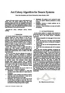
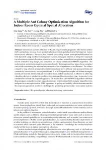
In a recent development 15, 61: much attention is given to the evolutionary design of arithmetic circuits as they provide the essential building blocks needed for larger DSP applications. Such effort has resulted in the development of arithmetic circuits that range from a simple sequential adder to the more complex 3-hit multiplier. The work of Fogarty [7] and Miller [5. 81 claimed to build some arithmetic circuits that cannot he produFed by human designer's conventional methods. Coello et al. [9] proposed a similar approach to evolve a circuit, which they claimed was hetter than that of Miller's. Several other algorithms such as Cartesian Genetic Programming. Ant Colony Optimization, and Particle Swarm Optimization have also been used for evolutionary logic design [6, IO, I I]. A complete review and taxonomy of the field could he found in [12. 13, 141. Although most of the existing techniques in evolutionary design were able to arrive at solutions that are difficult to obtain using conventional methods, there exist many open problems that were still not addressed. A numher of these problems are described below. Circuit representations: Most of. the puhlished work in evolutionary logic design used a two-dimensional matrix of n x m to represent a circuit. The position of circuit's outputs will most likely be placed at cell(0,rn - 1). However, it may happen that the hest solution can be found at ceIKi,j), 0 < i < n, 0 < j < m. But some redundant gates existing between this cell and the output cell may degrade the quality of the solution. The problem becomes complicated even further when the number of circuit's output is more than one. Figure I illustratrs the problem arises from circuit representation. Functional fitness calculation: The value of functional fitness depends on the numher of correct matchings between the output's pattern of the obtained solution and the truth table of the intended circuit. The higher the numher of hits achieved, the higher the value of the functional titness. This argument is not always true in logic design. A solution that has low functional fitness can be inverted to have a high functional fitness (see Figure 2). Objectives of the optimization: Most of the existing techniques use gate count as their objective for optimization. With the increasing need for high performance and low
708
(at
(b)
Figure 1: Problems that may appear in matrix representation.
e)
(a)
(d
Figure 2: An evolved two-hit odd parity circuit. (a) Fitness of F1 = 0 (h) Adding an inverter. fitness of FI = I (c)~Toggle the type of pate (XNOR --f XOR), fitness of FI = I power circuits. the ohjective of only minimizing pate count is not anymore acceptable.
that cell(i: k)? 0 < i < n, 0 < k any of the cells in column k 1.
This paper is organized as follows: first. problem and cost function formulation are presented. Then. the modified ACO for logic design is discussed. Finally. performance evaluation and comparison with existing tachniques are given.
It is known that each type of gate has different characteristics for different technology. These characteristics include area. base delay and capacitance input (output) of the gate. Although u'e can build any logic circuit using AND, OR and NOT pates. we need to have a rich (hut limited) gate library to he able to obtain different structures of the circuils. The best circuit can then be chosen based on the multiohjective critefia applied in the algorithm. Therefore, ien types of gates are considered. Table I shows these fates.
2 Problem and Cost Function Formulation Evolutionary computation views the problem of logic design as a search task. The methodology explores a solution space larger than that of the desired function. hut gradually pulls the specification of the circuit towards the target truth tahle. However. the design space of digital circuits is huge. There are 2" (C:") possible solutions that satisfy 2" - 1out of 2" truth tahle's pattern for a n n inputs single output function. In addition to that, the number of possible structures representing each of these solutions is many. These different structures represent different design ob.jectives and/or constraints. Exploring the whole search space is impractical. Therefore, the search space sampled hy the algorithm must have its size limited. In this paper, we use the structure proposed i n [3]. Each cell of the n x m matrix contains the information of the gate type and its corresponding inputs. However, unlike Ihc fixed interconnection rules used in [3].we allow the output of aach cell in column j to he connected to any of the cells in column j 1 (j > 0, j 1 < m ) . Thus, it is possible
+
+
+
Gate ID
I
Inputs
0
)
a,b
I 1
< m. is not connected to
Galr WlKEl
1
1
Output a
NOT2
9
Table I : Gate types. Gate ID. and its corresponding Boolean function.
2:l Fitness Calculation The fitness of a solution consists of two parts: functional fitness and ohjective fitness. These are explained below.
709
Functional Fitness: The functional fitness deals with the functionality of the solution. i.e.; how good the solution is in satisfying the truth table of the intended Boolean function. Several functional fitness formulations are reported in the literature 1131. The commonly used one is the ratio of the number of correct hits to the length ofthe truth table. If F F denotes the functional fitness, then the formulation below is applied.
FF =
Number of hits Length o f the truth table
(1)
The solution has to he 'inverted' if the value of F F is less than 0.5. Therefore. the formulation of irormali:ed F F (FF,) below is applied:
FF,, = h.laz{FF, 1 - F F }
(2)
Objective Fitness: The ob,jective fitness ( O F ) is the measure of the quality of solution in terms of optimization ohjectives such as area, delay, gate copni,and power consumption. Formulation of cost functions used to estimate these values is given as follows. If G is the set of possible gate types and gi E G, the cost for gate count is formalized as follows: COStgate.eount
si
=
Where C: is the capacitance of the input node of a gate j driven by gate'i and C; represents the interconnect capacitance at the output node of cell i. The total power consumption can he approximated by the following equation 1151.
Where Pt is the total power consumption, VDDis the supply voltage. Si is the switching probability at the output node of cell i, i.e.. the average numher of transitions per clock cycle at the output of gate i. f is the clock frequency and p is a technology dependent constant. The cost of the overall power consumption in VLSI circuits can then be estimate3 as follows.
COStpou,ler =
Obj =
iEG,i#WIRES
COStnreo =
'
itG,i#WIRES
4gi) .
(4)
Where A ( g i ) is the area.of gate g ( i ) . The propagation delay of signals in VLSI circuit consists of two elements, switching delay of gates and interconnect delay. If a path ?I consists of n gates {vl, v2, ..., vn}, then, the delay T, along ?I is expressed by the following equation: .. "-1
T,, = c ( C D i
+ ((LFi+ Ri)
X
C;))
i= 1
Where CDi is the switching delay of the cell driving gate ui. LFi is the load factor of the driving block, Ri is the interconnect resistance of net u i , and Ci is the load capacitance of cell i given-by Equation 5. Since the value of Ri is constant, it can he neglected. The overall circuit delay is determined by the delay along the longest path (the most critical path). The total'capacitance Ci of bate .i consists of ihe interconnect capacitance at the output node of gate i and the sum of the capacitances of the input nodes of the gates driven by gate i.
c, = c: +
'
(7)
In order to indicate whether a given solution is satisfying a certain constraint, objective fitness is formulated as follows. Note that the constraint values states the upper hound for a specific objective.
(3)
The cost for area of VLSI circuits is stated as follows.
c si ci
iEM
Cost
Cost + Constraint
(8)
With this formulation. the solution that satisfies the area constraint will have Obj,,,, greater than 0.5. Any solution that has Obj,,,, less than 0.5 will not he considered. The objective fitness is then calculated as follows.
The weights for each elements of O F decide the emphasis of the optimization process. It is also possible to consider more.than one objective,
Overall Fitness Calculation: The formulation of overall fitness function is shown in Equation IO. U,./ is the weight for functional fitness. The value of T4-t determines the trade-off in the searching process, whether to have solutions better in terms of F F (or O F ) . Since the goal is to ohtain working circuits. the value of IVj must he large enough. However, it should not be too large in order to accommodate the O F part. Initial experiments showed that the setting of bV/ = 0.5 is appropriate for small circuits (up to four variables). However, these values cannot he used for bigger circuit.
OvF = W f . F F F + (1 - W f ). O F
c," ]EM.
710
(IO)
Figure 3: Some ofthe possihle paths in the function .f ing locked cells will he locked as well. All other cells will assume the status 'I' (removed). The cells that assume status 'r' will he removed at the end of each iteration. These empty cells will he then filled up again at the beginning of the next iteration. Figure 5 shows the pseudocode of the proposed algorithm. ..
S(0,Ol
S(0.I)
......
SlI.0)
S(l.1)
...... S(1.m-11
.....
......
S(n-1.0)%n-1.1)
...... ......
Modified ACO algorithm For MAXITER numher of iteration d o Fill the matrix ' ACO algorithm Ant activity Pheromone update Remove unfit cells End For Return the hest path end Algorithm
SIO.rn-Il
Figure 5 : Modified Ant Colony Algorithm.
... .... S,,,-l.m-i
Figure 4: Nest cell and matrix A4 for ant tn he traversed. A circuit is modelled as a matrix A.I of sire n x m. The cnntent of matrix A I is dynamically filled. At first. matrix M is filled with randomly generated cells. Then, each ant will traverse the matrix. These ants originate from a dummy cell called nesf (see Figure 4). and traverse each state (a cell in a column) until it reaches the last column or a cell that has no successor. After the ants finish traversing the matrix, all cells are checked to see whether to he kept or not. Each cell can assume two different status, namely: 'I' (locked) or 'r' (removed). The cells that are included in the hest path(s) will assume the status of 'I' (locked). And the cells rhat are feed-
3.1 Pheromone Trail Calculation and,Update The selection of which edge to traverse is determined by a stochastic process. e.g.. Roulette Wheel. Therefore. the probability of choosing each edge must be calculated in advance. This probahility depends on the pheromone value ( r )and the heuristic value (7)of the corresponding edge (or the next cell), or can be formulated below.
The value of CY and fi imply the preference of the search, whether it depends more on the pheromone value or the heuristic value. Every newly created cell will he given an initial and small amount of pheromone value. This value will be updated every iteration hy the ant.
71 1
The heuristic value ( q )depends on the distance of FF, values between cells. The distance d between cells is formulated as follows. d = FF,(i
+ 1) - FF,(i)
1) = d
+ 0.5
1. Q = I 2. p = 2 3. p = 0 . I 4. 5. 6. 7.
(12)
Numherpf ants = 10 numher of inputs Numher of generation = 10 Maximum iteration = 2000 (four input circuits) or 3000 (five input circuits) 8. Number ofruns = 10-15 9. Size of the matrix = (2 * number of inputs) x (2 * number of inputs)
(13)
The addition of 0.5 in the calculation of 1) is meant to normalize the value o f q into l0.11. A decrease of the functional fitness means that the value of 1) is in the range of [0,0.5), while an increase of the functional fitness makes the value of 17 in the range of (0.5. I ] While traversing the matrix, every ant carries the information of the paths taken so far. e.g., the row index of all cells that are visited. If an ant reaches a cell that has no successor, the overall fitness ofthe solution built by the ant will he evaluated. When all ants finish their tour, pheromone update is performed. The pheromone update consists of two procedures. pheromone addition and pheromone evaporation. However, as has been shown in [161, it is better to limit the number of ants that can put addirional pheromone. Thus. only certain number of 'the best'. ants can track their path(s) hack and put some additional pheromone on it. The pheromone addition i~sperformed using the following equation:
T(t)
T(t)
+AT
It should he noted that we avoid using gate count as the measure of objective for sewral reasons. Firstly. the term 'gate' or hasic module for the evolutionary logic design depends on the definition of the gate library that is used. One may use NAND gates, or a set of AND, OR and XOR gates. or MUXes. or a combination of all these. Secondly. each of the aforementioned gates has different characteristics. We can assume that an XOR gate as an atomic gate. However. this may not be the case for all target implementations. For example, in standard cell design, an XOR. gate requires more area compared to an AND gate. and an AND gate requires more area than an NANDgate. This is in contrast with FPGA. in which all types of gate can tit into one cell. Nevertheless. if the target implementation is an P G A . calculating the area is proportional to calculating the gate count. In this context. the proposed algorithm is more general as compared to the existing techniques. However, since most ofthe published work in evolutionary logic design use the gate count as a measure of quality, u e provide a comparison of our results in terms of gate count as well.
(15)
where OvF(b) denotes the overall fitness of thc solution that the ants built, AT is the additional pheromone and A is a constant. Next, pheromone evaporation will take place using the following formula. 7
= (1 - p ) x
7,. with p
= ( 0 : 11
1r;f = [ O S . 0.751
5 Performance Evaluation and Comparison, Several circuits of different complexity have been used to test the proposed algorithm. For the sake of simplicity. the truth table of the circuits will he represented as a string of zeros and ones. Table 2 shows the circuits used for performance evaluation. Note that these circuits represent single output Boolean functions.
(16)
While traversing the matrix. the ants will memorize the best cell visited along the path. The paths from nest to the hest cell will hcreturned. The remaining part of the path . . will be discarded hy the ant. When,the maximum number of iterations is reached. the best solution is returned. In case of multiple output circuits. multiple colony of ants are used. In this context. each colony of ants is assigned to find a specific output of the circuit. All colonies will share the same matrix. The possibility of using the same suh-functions is established by sharing the pheromone value among different colonies.
4 Experimental Setup
Table 2: Circuits used to test the performance of the proposed approach.
The technology parameters are obtained using CMOS 0.25. micron library from MOSIS 1171. The parameters used for experiments are as follows:
Figure 6 shows the behavior of the proposed algorithm for area optimization of Circuit1 for the first 100 iterations.
712
8.2
-
4 ......... i -
;..
. .
...................................................
CL
..... Normalized Area 0.2
-
Normalized'Delay
I 21
51
I,
81
Figure 6: Functional fitness and satisfaction of objectives for the first 100 iterations. In this figure, the area, delay and power consumption are normalized so that the behavior of' the proposed approach can he ohserved easily. As can he seen. an increase in functional fitness mostly requires an increase in some of the objectives. But then. if there is no increase in the functional fitness. minimization of objectives is ohserved. The proposed algorithm is able to arrive at a functionally correct circuit for the intended truth table after only 20 iterations. Around iteration 100, a significant increase in the delay of the solution is ohserved. However. since the emphasi7.z of the current course of action is optimization of area. then new solution that has less area but higher delay is accepted. Circuit
Oh,ircrivrs ..
Circuill
Delay Optimized BeE, Ax'erage ~. ~. 0.99 0.81
delay
I
power
11.07
1 I I
1
1
Power Optimized Best Average ~.
1
~~
1
1 1
1.04 1.06
0.75
I
0.97
0.78
I
0.96
1.00
1.10
I1.00
1.00
1 1
Circuit?
__ Circuiii
__ Circuit4
, Circuit5
-.
area delay
power
, 1 I I
. .
0.94 1 1.05 1
0.91
0.94
0.97
I
1
1.54 I
1.09
Table 3: Results for the delay and power optimization. normalized with respect to the results of area optimization. The results of delay optimized and power optimized circuits are given in Tahle 3. Note that these values are normalized with respect to the results obtained from the area optimized circuits. The normalized area for each circuit in Ta-
ble ? should he less than or equal to one. As can he seen. except for Circuit5, the delay optimization scheme produced hetter circuits in terms of delay (normalized dclay 5 I ). at the expense of larger area andlor power consumption. These results show the effectiveness of the proposed algorithm. In order to compare our algorithm with known puhlished work. some circuits are tested and compared to the results reported in 19, IO]. Some selected circuits from Table 2 with the addition of ?-bit multiplier and 2-hit adder with carry circuits are used for comparison. An overall compdrison is shown in Table 4. For multiple output circuits. multiple colony of ants are used. In a 2-hit adder circuit for example, we need three colony of ants to find all the three outputs of the circuits. Each colony will find the assigned circuit's output. The sharing of pheromone value hetween colonies makes the sharing of sub-functions possible. However, this sharing can indeed bias the search..since the second colony of ants 'smell' the pheromone that was updated hy the first colony ofants, and the third colony will 'smell' the pheromone that will he updated by the second colony, and so on. This is the reason why the value of p of Equation I 1 is set equal to 2 during the course of the experiment. With higher value of /3. the search is more dependent on the heuristic value q. which emphasizes finding the functionally correct circuits. Figure 1 shows the functional fitness value of each outputs of a 2-hit adder circuit. Notice that the ants will find outputs of the circuit one by one. In analogy with the process of ants finding the food. the simplest function (the closest) will he obtained first and the most complex1 function (the furthest) will most likely be obtained the last. In this context. for 2bit adder circuit. the first sum will be obtained first while the carry out will he obtained the !as.
713
1 Gatr Count 1 Am(rnicron1
Resultins Function
___
F = (X + YjZ 0 XY
Proposed Approach
AnISystemjlO]
MGA I91 AnlSysleniIlOl
7"
17496
F=(((M'+Y)OZ)+Xf)((~'Z)'Q(X'CI.))
9
19197
+ (Y 0 2 ) )0 (Wm)
6
12393
6.:
1552
F = ((At? B)€J AD)
F = ( ( A0 D) . C')
(m0(.40E ) )
I8468 14337
7
17253
Fo = AB: FI = AD 8 BC Fz = C D 9 ABCD: F3 = ABCD
7
17253
e BC __ __ _ _ &=E.A F ~B =B :C . A D
7
12636
I1
24300
,
Fo = AB: Fi = AD 8 BC F2
[in]
,* 7
MGA (91
~ n Sysrrm t
+ ( C + (A 0 D))'
F=((B~D)R(A+D))e((B+C)+(.A0Dj)'
Proposed Approach
mu12
__
F = (-1
Proposed Approach
Circuit8
7776
F=((o'.ewx)0((z+x+Y)eZ)j'
MGA 191 Circuit7
1
= CD
.4BCD: F3 = ABCD
_ _
Fa = AB: F1 = A D
PlV3pOsrd AppKW2h
Fo = A O B O C add?,
PropusedApproach
.
__
FI = ( A O B ) + C i 3 ( D Q E O ( A + B ) j
_ _ _ Fs = D E .( ( A + B )i (DE, E ) ) + ( ( A B E ) + C )
. .
6 Conclusion . '
Bibliography
In this paper, we have presented a modified ant colony algorithm for evolutionary logic design. The modification is performed in order to suit the problem instance and to handle some of the problems that are not addressed by existing techniques. Performance ofthe proposed approach and comparison with the existing techniques are shown. In all cases, the results obtained using the proposed approach outperformed those obtained using existing techniques.
[ I ] M. Dorigo. M. Maniezzo. and A. Colorni. The Ant Systems: An Autocatalytic Optimizing Process. Revised 91-016. Dept.,ofElectronica. Milan Polytechnic. 1991.
Acknowledgment
[3] Sushi1 J. Louis. Geiieric AIgoritlints as U Conipurarioriul Tool f i r Desipri. PhD thesis. Department of Computer Science, Indiana University, Aug 1993.
121 Hugo de Garis. Evolvable Hardware: Genetic Programming of a Darwin Machine. Proceedings o f t h e Irirenrurioiial Coifereire irr Irrrrsbrirck. Austria, pages 4 4 1 4 4 9 , Springer-Verlag. 1993.
We would like to acknoa,ledge the continued support for our research from.King Fahd University of Petroleum & Minerals. This work was supported under project entitled "Iterative Heuristics for the Design of Combinational Logic Circuits".
[41 Adrian Thompson. Silicon Evolution. Proceedirigs of the Firsr Aiiriual Cori,fererrce on Genetic Prograniniing, pages 444-442, MIT Press, 1996.
714
oarI
0.7
0.6 :
i
0.5 1
>at
201
4a-
301
501
601
.
701
. .
Figure 7: Functional fitness of 2-hit adder.
[SI 1. F. Miller. D. Joh. and Vassilev V. K. Principles in the Evolutionary Design of Digital Circuits - Part I. Joiw iral of Genetic Progranriiriirg arid Ei:oli,ableMachiiies. 1(1):8-35. 20N).
fenis: Froiir
Coifererice. ICES 2003,2606:398-409, Mar 2003. [ 121
161 J. F. Miller and P. Thomson. A Developmental Method for Growing Graphs and Circuits. Fifth lriterriarioiral Coiifererice oti Evolvable S!sfeiiis: Frorir Biology to Hardware. 26069-104. Mar 2003. 171 T. Fogany. J. E Miller. and P. Thornson. Evolving Digital Logic Circuits on Xilinx WOO Family FPGAs. The 2rrd Oirlirie Coifereiice or1 Sof Corirpurirrg iri. €11girrecririg Desigir arid Moiiiifacrurirrg, pages 299-305, Springer-Verlag, London. 1998. [8] I. F. Miller. T. Fogarty. and P Thomson. Designing Electronic Circuits Using Evolutianary Algorithms. Arithmetic Circuits: A Case Study. Genetic Algor i t h m aird Evolution Strategy in Erigirieeririg aiid Conrputer Science. Johri Wile! arid Som. Chichesrer. pages 105-131. 1998.
[IO] C. A. Coello. A. D. Christiansen. and A. H. Aguirre. Ant Colony System for the Design of Combinational Logic Circuits. Esolvable Systenrs: From Biolog,! ro Hardware. Ediirburgh, Scotlarid. pages 21 -30. April Springer Verlag. 2000.
[ I I ] C . A. Coello and Hernandez Luna and Erika and A.H. Aguirre. Use of Panicle Swarm Optimization to De-
R. S. Zehulum. M. A. Pacheco. and Marley Vellasco. Evolvahle Systems in Hardware Design: Taxonomy. Survey and Applications. Esolvable S w e i i i : Frorii Biolog: to Hardwme. Proceeding of the First Interiiatioiral C o i f e r t k . ICES 94 T,rikba. Japan. Lecture Nore.7 01 Co171puterScience. 1259344-358, Oct. 1997.
[ I ? ] R. S. Zehulum. M. A. Pacheco, and Maria Vellasco. E i ~ o l a t i o i i oElectmiiics: ~ Autoniutic Design of Necrroiiic Circuits aird Systeiirs by .Gerieric Algorithiirr.
CRC Press. 2002.
1141 Xin Yao and Tetsuya Higuchi. Promises and Challenges of Evolvahle Hardware. IEEE Trans. on S w fenis. Maii. mid Cyberiierics - Part'C: Applicatiorrs aird
Reviews. 29( 1):87-97. 1999. [ 151 Srinivas Devadas and Sharad Malik. A Survey of Opti-
mization Techniques Targeting Low Power VLSI Circuits. 32iid ACM/IEEE Desigri Autoniation Cotiferetrce. pages 242-247. 1995:
[91 C. A. Coello and A. H. Aguirre.. Evolutionary Multiohjective Design of Cornhinational Logic Circuits. Proceedirrgs of die Secorid NASMDoD Workshop or1 Ei801vableHardwar-e,pages 161-1 70. Jul2000.
E~oI~~uB S lw e Biolog? to .Hardware. 5th Irireniariorral
sign Cornhinational Logic Circuits.
[ 161 T. Stutzle and H. Hoos. Improvements of the ant system: lntroducing MAX-MIN ant system. Proceedirig of rhe Iriterriatiorral Coifererice on Artificial Neilral Nencorks arid Genetic Algori/hnis. pages 245-249. 1997.
1171 MOSlS Standard Cell Library f o r ' CMOS. http:/lwww.mosis.org/Technical/Designsuppor~stdcell-library-scmos.html.
715