For example, Pentium-class proces- sors currently take well over 100W and processors in the year 2015 are expected to take close to 300W [7]. Increased.
In Proceedings of the Workshop on Complexity-Effective Design(WCED), June 2003
A Multi-Core Approach to Addressing the Energy-Complexity Problem in Microprocessors Rakesh Kumar Keith Farkas* Norman P Jouppi* Partha Ranganathan* Dean M. Tullsen Department of Computer Science and Engineering University of California, San Diego rakumar,tullsen @cs.ucsd.edu
�
� HP Labs
1501 Page Mill Road Palo Alto, CA 94304 keith.farkas,norm.jouppi,partha.ranganathan @hp.com
�
Abstract This paper proposes single-ISA heterogeneous multicore architectures as a mechanism to reduce processor power dissipation. It assumes a single chip containing a diverse set of cores that target different performance levels and consume different levels of power. During an application’s execution, system software evaluates the resources required by an application for good performance and dynamically chooses the core that can best meet these requirements while minimizing energy consumption. It describes an example architecture with five cores of varying performance and complexity. Initial results show a more than three-fold reduction in energy at a cost of only 18% performance.
1 Introduction As processors continue to increase in performance and speed, processor power consumption and heat dissipation have become key challenges in the design of future highperformance systems. For example, Pentium-class processors currently take well over 100W and processors in the year 2015 are expected to take close to 300W [7]. Increased power consumption and heat dissipation typically leads to higher costs for thermal packaging, fans, electricity, and even air conditioning. Higher-power systems can also have a greater incidence of failures. In this paper, we propose a single-ISA heterogeneous multi-core architecture to reduce processor power dissipa-
tion. Prior chip-level multiprocessors (CMP) have been proposed using multiple copies of the same core (i.e., homogeneous), or processors with co-processors that execute a different instruction set. We propose that for many applications, core diversity is of higher value than uniformity, offering much greater ability to adapt to the demands of the application(s). We present a multi-core architecture where all cores execute the same instruction set, but have different capabilities and performance levels. At run time, system software evaluates the resource requirements of an application and chooses the core that can best meet these requirements while minimizing energy consumption. The motivation for this proposal is that different applications have different resource requirements during their execution. For example, some applications may have a large amount of instruction-level parallelism (ILP), which can be exploited by a core that can issue many instructions per cycle (i.e., a wide-issue superscalar CPU). The same core, however, might be wasted on an application with little ILP, consuming significantly more power than a simpler core that is better matched to the characteristics of the application. Hence, it is might be possible to run an application on the core with appropriate-complexity instead of running on the core with highest complexity and yet achieve similar levels of performance. Previous work on power-related optimizations for processor design can be broadly classified into two categories (1) work that uses voltage and frequency scaling of the processor core to lower power [13, 21], (2) work that uses “gating” - the ability to turn on and off portions of the core - for power management [8, 18, 14, 19, 12, 15, 11]. Our hetero-
geneous multi-core architecture does not preclude the use of these techniques and can potentially address the drawbacks of these techniques to provide much greater power savings. For example, voltage and frequency scaling reduces the parameters of the entire core. While this reduces power, the power reductions are uniform, across both the portions of the core that are useful for this workload as well as the portions of the core that are not. Furthermore, the power benefits are fundamentally limited by the process technology in which the processor is built. Similarly, gating-based approaches do not address the power consumed from driving wires across the idle areas of the processor core. One way to implement a heterogeneous multi-core architecture is to take a series of previously implemented processor cores, modify their interfaces, and combine them into a single multiprocessor. This ensures complexity-effective designs which can be relatively easily tested and validated. Given the growth between generations of processors from the same architectural family, the entire family can typically be incorporated on a die only slightly larger than that required by the most advanced core. In addition, clock frequencies of the older cores would scale with technology, and would be much closer to that of the latest processor technology than their original implementation clock frequency. Then the primary criterion for selecting between different cores would be the performance (e.g., IPC) of each architecture and the resulting energy dissipation. In this paper, we consider implications of this single-ISA heterogeneous architecture, with particular attention to one example architecture – it includes five representative cores (three in-order cores and two out-of-order cores) from an ordered complexity/performance continuum.
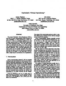
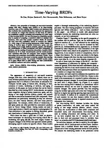
of power and performance) for one application may not be best for another. One application may benefit greatly from wide issue and dynamic scheduling, another benefits from neither. Thus, the latter gains nothing from the extra power required for it to run on a high-performance processor. This hypothesis motivates the inclusion of a diverse set of cores on the die. To provide an effective platform for a wide variety of application execution characteristics, the cores on the heterogeneous multi-core processor should cover both a wide and evenly spaced range of the complexity/performance design space. The initial study considers a design that takes a series of previously implemented processor cores with slight changes to their interface – this preserves one of the key advantages of the CMP architecture, namely the effective amortization of design and verification effort. For breadth, we include both a single-threaded version of the EV8 (Alpha 21464), referred to as EV8-, and the MIPS R4700, a processor targeted at very low-power applications. To fill out the design space, we also include the EV4 (Alpha 21064), EV5 (Alpha 21164), and EV6 (Alpha 21264). Core switching is greatly simplified if the cores can share a single executable, so we assume a variant of the R4700 that executes the Alpha ISA. Finally, we assume the five cores have private L1 data and instruction caches and share a common L2 cache, phase-lock loop circuitry, and pins. We chose the cores of these off-the-shelf processors due to the availability of real power and area data for these processors, except for the EV8 where we use projected numbers [10, 16, 6, 5]. All these processors have 64-bit architectures. Figure 1 shows the relative sizes of the cores used in the study, assuming they are all implemented in a 0.10 micron technology (the methodology to obtain this figure is described in the next section). It can be seen that the resulting core is only modestly (within 15%) larger than the EV8core by itself.
2 Architecture This section gives an overview of a potential heterogeneous multi-core architecture and core-switching approach. The architecture consists of a chip-level multiprocessor with multiple, diverse processor cores. These cores all execute the same instruction set, but include significantly different resources, and achieve different performance and energy efficiency on the same application. During an application’s execution, the operating system software tries to match the applications to the different cores so as to make the best use of the available hardware while maximizing energy efficiency for a given performance requirement or goal.
For this research, to simplify the initial analysis of this new execution paradigm, we assume only one application runs at a time on only one core. This design point could either represent an environment targeted at a single application at a time, or modelling policies that might be employed when a multithreaded multi-core configuration lacks thread parallelism. But because we assume a maximum of one thread running, the multithreaded features of EV8 are not needed. Hence, these are subtracted from the model, as discussed in Section 3. In addition, this assumption means that we do not need more than one of any core type. Finally, since only one core is active at a time, we implement cache coherence by ensuring that dirty data is flushed from the current core’s L1 data cache before execution is migrated to another core.
2.1 Choice of cores. Our heterogeneous multi-core architecture is based on the hypothesis that the performance difference between the cores varies across different workloads. In other words, the “best” core (defined, for now, as some desired combination 2
when we power down a processor core we do not power down the phase-lock loop that generates the clock for the core. Rather, in our multi-core architecture, the same phaselock loop generates the clocks for all cores. Consequently, the power-up time of a core is determined by the time required for the power buses to charge and stabilize. In addition, to avoid injecting excessive noise on the power bus bars of the multi-core processor, a staged power up would likely be used. We estimate that such a power up could be completed in roughly 1000 cycles, or 500ns.
R47 00 EV4
EV8-
EV5
EV6
3 Methodology Figure 1. Relative sizes of the cores used in the study
This section discusses the various methodological challenges of this research, including modeling the power, the real estate, and the performance of the heterogeneous multicore architecture.
This particular choice of architectures also gives a clear ordering in both power dissipation and expected performance. This allows the best coverage of the design space for a given number of cores and simplifies the design of core-switching algorithms.
3.1 Modeling of CPU Cores As discussed earlier, the cores we simulate are roughly modelled after cores of R4700, EV4 (Alpha 21064), EV5 (Alpha 21164), EV6 (Alpha 21264) and EV8-. EV8- is a hypothetical single-threaded version of EV8 (Alpha 21464). The data on the resources for EV8 was based on predictions made by Joel Emer [10] and Artur Klauser [16], conversations with people from the Alpha design team, and other reported data [6, 5]. The data on the resources of the other cores are based on published literature on these processors [1, 2, 3, 4]. The multi-core processor is assumed to be implemented in a 0.10 micron technology. The cores have private firstlevel caches, and share an on-chip 3.5 MB 7-way setassociative L2 cache. At 0.10 micron, this cache will occupy an area just under half the die-size of the Pentium 4. All the Alpha cores (EV4,EV5,EV6,EV8-) are assumed to run at 2.1GHz. This is the frequency at which an EV6 core would run if its 600MHz, 0.35 micron implementation was scaled to a 0.10 micron technology. All of the Alpha cores were designed to run at high frequency, so we assume they can all scale to this frequency (if not as designed, processors with similar characteristics certainly could). On the other hand, the R4700 is not designed primarily for high clock rate; thus, we assume it is clocked at 1 GHz. The input voltage for all the cores is assumed to be 1.2V. Table 1 summarizes the configurations that were modelled for various cores. We did not faithfully model every detail of each architecture, but we were most concerned with modeling the approximate spaces each core covers in our complexity/performance continuum. However, all architectures are modelled as accurately as possible, given the parameters in Table 1, on a highly detailed instruction-level simulator.
2.2 Switching of workloads between cores. The second hypothesis in our study is that different cores have varying energy efficiencies for the same workload. Typical programs go through phases with different execution characteristics – the best core during one phase may not be best for the next phase. This observation motivates the ability to dynamically switch cores in mid execution to take full advantage of our heterogeneous architecture. There is a cost to switching cores, so we must restrict the granularity of switching. One method for doing this would switch only at operating system timeslice intervals, when execution is in the operating system, with user state already saved to memory. If the OS decided a switch was in order, it would trigger a cache flush to save all dirty cache data to the shared L2, power up the new core, and signal the new core to start at a predefined OS entry point. The new core would then power down the old core and return from the timer interrupt handler. The user state saved by the old core would be loaded from memory into the new core at that time, as a normal consequence of returning from the operating system. Alternatively, we could switch workloads to different cores at the granularity of the entire application, possibly chosen statically. In this study, we consider both these options. In this work, we assume that unused cores are completely powered down, rather than left idle. Thus, unused cores suffer no static leakage or dynamic switching power. This does, however, introduce a latency for powering a core back up. We assume that a given processor core can be powered up in approximately one thousand cycles of the 2.1GHz clock. This assumption is based on the observation that 3
Processor Issue-width I-Cache D-Cache Branch Pred. Number of MSHRs
R4700 1 16KB, 2-way 16KB, 2-way Static 1
EV4 2 8KB, DM 8KB, DM 2KB,1-bit 2
EV5 4 8KB, DM 8KB, DM 2K-gshare 4
EV6 6 (OOO) 64KB, 2-way 64KB, 2-way hybrid 2-level 8
EV88 (OOO) 64KB, 4-way 64KB, 4-way hybrid 2-level (2X EV6 size) 16
Table 1. Configuration of the cores As noted, our emphasis was on evenly covering the complexity space rather than complete faithfulness to the original designs. Specific details of the implication of this emphasis include the followig. Associativity of the EV8caches is double the associativity of equally-sized EV6 caches to account for increased speculation due to higher issue-width. EV8- uses a tournament predictor double the size of the EV6 branch predictor. All the caches are assumed to be non-blocking, but the number of MSHRs is assumed to double with successive cores to adjust to increasing issue width. All the out-of-order cores are assumed to have big enough re-order buffers and large enough load/store queues to ensure no conflicts for these structures. The various miss penalties and L2-cache access latencies for the simulated cores were determined using CACTI. CACTI [29, 25] provides an integrated model of cache access time, cycle time, area, aspect ratio, and power. To calculate the penalties, we used CACTI to get access times and then added one cycle each for L1-miss detection, going to L2, and coming from L2. For calculating the L2 access time, we assume that the L2 data and tag access are serialized so that the data memories don’t have to be cycled on a miss and only the required set is cycled on a hit. Memory latency was determined to be 150ns.
from datasheets (except for EV8-). For the EV8 L2, we assumed 32 byte (288 bits including ECC) transfers on reads and writes to the L1 cache. We also assumed the L2 cache to be doubly pumped. The power dissipation at the output pins was calculated using the formula: .
����� ��
������������
The values of V (bus voltage), f (effective bus frequency) and C (load capacitance) were obtained from datasheets. Effective bus frequency was calculated by dividing the peak bandwidth of the data bus by the maximum number of data output pins which are active per cycle. The address bus was assumed to operate at the same effective frequency. For processors like the EV4, the effective frequency of the bus connecting to the BCache is different from the effective frequency of the system bus, so power must be calculated separately for those buses. We assume the probability that a bus line changes state was 0.5. For calculating the power at the output pins of EV8, we used the projected values for V and f. We assumed that half of the pins are input pins. Also, we assume that pin capacitance scales as the square root of the scaling factor. Due to reduced resources, we assumed that the EV8- core consumes 80% of the calculated EV8 core-power. This reduction is assumed primarily due to smaller issue queues and register files. The power data was then scaled to the 0.10 micron process. For scaling, we assumed that power dissipation varies directly with frequency, quadratically with input-voltage and is proportional to feature-size.
3.2 Modeling Power Table 2 shows our power and area estimates for the cores. Power dissipation for all implemented cores is derived from published numbers, forcing us to start with peak power data obtained from datasheets and conference publications [1, 2, 3, 4, 16, 6]. Actual power dissipation will vary with activity, which we do not model inside the cores (but do at the L2 cache).While this basis ensures that our power estimates are high, we believe that the typical power for each core scales roughly with peak power. This gives us an adequate yardstick to determine the initial feasibility of this approach, which is the primary goal of this paper. To derive the peak power dissipation in the core of a processor from the published numbers, the power consumed in the L2-caches and at the output pins of the processor must be subtracted from the published value. Power consumption in the L2 caches under peak load was determined using CACTI, starting by finding the energy consumed per access and dividing by the effective access time. Details on bitouts, the extent of pipelining during accesses etc. were obtained
The second column in Table 2 summarizes the power consumed by the cores at 0.10 micron technology. As can be seen from the table, the EV8- core consumes almost 200 times the power and 80 times the real estate of the R4700 core. CACTI was also used to derive the energy per access of the shared L2-cache, for use in our simulations. We also estimated power dissipation at the output pins of the L2cache due to L2-misses. For this, we assumed 400 output pins. We assumed a load capacitance of 50pF and a bus voltage of 2.5V. Again, an activity factor of 0.5 for bit-line transitions was assumed. We also ran some experiments with a detailed model of off-chip memory access power, but found that the level of off-chip activity is highly constant across cores. 4
Core R4700 EV4 EV5 EV6 EV8-
Core-power (Watts) 0.453 4.970 9.827 17.801 92.880
�����
Core-area ( ) 2.80 2.87 5.06 24.5 236
�����
Benchmarks are simulated using SMTSIM, a cycleaccurate, execution-driven simulator that simulates an outof-order, simultaneous multithreading processor [26, 27]. SMTSIM executes unmodified, statically linked Alpha binaries. The simulator was modified to simulate a multi-core processor comprising five heterogeneous cores sharing an on-chip L2 cache and the memory subsytem. Because the R4700 does not execute Alpha binaries, what we are modeling is an R4700-like architecture targeted to the Alpha ISA. In all simulations in this research we assume a single thread of execution running on one core at a time. Switching execution between cores involves flushing the pipeline of the “active” core and writing back all its dirty L1 cache lines to the L2 cache. The next instruction is then fetched into the pipeline of the new core. Both the execution time and energy of this overhead, as well as the startup effects on the new core, is accounted for in our simulations of the dynamic switching heuristics in Section 4. Programs are fast-forwarded for 2 billion committed instructions and simulated for 1 billion committed instructions, starting with a cold cache. All benchmarks are simulated using ref inputs. In experiments to understand application phase behavior, data was collected after every 1 million committed instructions.
Power/area Watt/ 0.162 1.732 1.942 0.726 0.393
Table 2. Peak Power and area statistics of the cores Program ammp applu apsi art bzip2 crafty eon equake fma3d gzip mcf twolf vortex wupwise
Description Computational Chemistry Parabolic/Elliptic Partial Differential Equations Meteorology:Pollutant Distribution Image Recognition/Neural Networks Compression Game Playing:Chess Computer Visualization Seismic Wave Propagation Simulation Finite-element Crash Simulation Compression Combinatorial Optimization Place and Route Simulator Object-oriented Database Physics/Quantum Chromodynamics
Table 3. Benchmarks simulated.
3.3 Estimating Chip Area
4 Initial Results
Table 2 also summarizes the area occupied by the cores at 0.10 micron (also shown in Figure 1). The area of the cores (except EV8-) is derived from published photos of the dies after subtracting the area occupied by I/O pads, interconnection wires, BIU (bus-interface unit), L2 cache, and control logic. Area of the L2 cache of the multi-core processor is estimated using CACTI. The die size of EV8 was predicted to be 400 [22]. To determine the core size of EV8-, we subtract out the estimated area of the L2 cache (using CACTI). We also account for reduction in the size of register files, instruction queues, reorder buffer, and renaming tables to account for the single-threaded EV8-. We used detailed models of the register bit equivalents (rbe) [20] for each structure at the original and reduced sizes. The sizes of the original and reduced instruction queue sizes were estimated from examination of MIPS R10000 and HP PA-8000 data [9, 17], assuming that the area grows more than linear with respect to the number of entries ( ). The area data is then scaled for the 0.10 micron process.
Figure 2 shows results for applu. Performance and power are modeled for each processor, with the ratio ) (essentially, the inverse of energy-delay ( product) shown on the Y axis. The bold line shows the core at each interval which minimizes the energy-delay product over that interval, with the constraint that we never choose a core that sacrifices more than 50% performance relative to EV8- over an interval. The line is drawn based on an offline analysis where locally-optimal decisions are made for each interval. Note that this does not represent an upper-bound on the savings because globally-optimal decisions might be very different. We could not find the upper-bound because of the quadratic integer-linear-programming nature of the problem. In this figure, four different cores are used for some interval. Compared to a single-core architecture (e.g., one that only contained the EV8- core), this configuration could ideally reduce the energy-delay product by 73.5% (a nearly 4X improvement in ). This comes from a combination of a 15% performance loss and a 77.7% energy savings (that’s a five-fold reduction in energy). The coarse granularity of switching means that the cost of switching has less than 1% effect on the overall performance. Table 4 shows the results for all the benchmarks assuming perfect knowledge(locally-optimal) on when to context switch. The results are shown relative to EV8-. As can be seen, the average reduction in energy-delay is 65%; the
46587 ")9�:�; *,*
!#"
4


![ModelSim Tutorial - UCSD CSE [PDF]](https://m.moam.info/img/260x300/modelsim-tutorial-ucsd-cse-pdf_64799306098a9e495b8b45ed.jpg)