A Multi-Energy Method of Non-Destructive Testing by Determination of the Effective Atomic Number of Different Materials Volodymir D. Ryzhikova, Oleksandr D. Opolonina, Serhiy M. Galkina, Yevheniy F. Voronkina Olena K. Lysetskaa, Serhiy A. Kostioukevitch b a Institute for Scintillation Materials of STC “Institute for Single Crystals”, NAS of Ukraine 60 Lenin ave., 61001, Kharkov, Ukraine,
[email protected] b Institute of Semiconductor Physics, Kiev, Ukraine ABSTRACT Development and studies of characteristics are reported for X-ray radiation detectors of “scintillator-photodiode” type showing improved spatial resolution with photosensitive area step of 1.6, 0.8, 0.4 and 0.2 mm and number of channels 16, 32, 128 and 256, respectively. The receiving-detecting channel has been adjusted and tested, appropriate software has been developed, and shadow X-ray images of tested objects were obtained. Evaluations were made of spatial resolution, resolution over thickness and detecting ability of the digital radiographic sysyem based on the detector array. Recommendations are formulated on application of such devices for non-destructive testing and technical diagnostics. Further studies on obtaining two-energy images show possibilities of substantial broadening of the application fields of the digital radiographic system, allowing determination of the effective atomic number Zeff for component substances of the tested objects. A possibility is shown of substance discrimination by their effective atomic number even for “light” elements with Zeff from 6 to 13. Clear distinction could be observed between such substances as water (Н2О) with Zeff≈7.43 and glycerol (СН2ОНСНОНСН2ОН) with Zeff≈ 6.87. Keywords: non-destructive testing, scintillator-photodiode, receiving-detecting circuit, spatial resolution.
1. INTRODUCTION The worldwide trend of transition from film radiography to digital radiography requires creation of advanced digital radiography systems (DRS) [1-4]. Materials of the 9th European Conference on non-destructive testing show that the main direction of DRS development is improvement of spatial resolution (SR) [4]. This work was aimed at looking for new possibilities of improvement of SR, resolution over thickness and detection ability of DRS based on X-ray radiation detectors of “scintillator-photodiode” (S-PD) type. Preliminary studies indicated two main technological problems hindering creation of S-PD detectors with improved SR [5]. One of them is preparation of scintillator arrays (assemblies) with small aperture of each scintillation element. The other is compact arrangement of pre-amplifiers (PA). We have proposed technical solutions for production and improvement of PD and scintillation arrays with number of channels from 32 to 256 on each PD, as well as detector design as a whole. 128- and 256-channel detectors using PD obtained from Hamamatsu or Bit, Kyiv, Ukraine have integrated electronics with amplifiers directly on the PD housing and a commutator scanning the channels, resulting in only 4 outlets at the PD output.
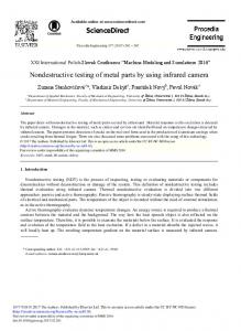
2.DESIGN DEVELOPMENT OF A DETECTOR WITH IMPROVED SR The X-ray radiation detector of S-PD type comprises two main elements – a multi-channel PD and a scintillator array (assembly). Previously used design of 16- and 32-channel PD imposes limitations on the directions of PD irradiation. These detectors can be used correctly only if irradiation is normal to the plane of photosensitive elements. In collaboration with Bit, Kyiv, Ukraine we have developed a new design of the 32-channel PD (Fig.1). Its advantages are: 1) all contacts of photosensitive elements are from one side of the silicon board;
Hard X-Ray, Gamma-Ray, and Neutron Detector Physics XII, edited by Arnold Burger, Larry A. Franks, Ralph B. James, Proc. of SPIE Vol. 7805, 78051P · © 2010 SPIE · CCC code: 0277-786X/10/$18 · doi: 10.1117/12.858267
Proc. of SPIE Vol. 7805 78051P-1 Downloaded From: http://proceedings.spiedigitallibrary.org/ on 05/19/2015 Terms of Use: http://spiedl.org/terms
2) the presence and location of a connector allows any desired position of the board with respect to the irradiation direction; 3) 2 adjustment openings are envisaged on the face side of the housing (the side without contacts). The first and the third feature allow reaching the identity of characteristics of detector couples (high-energy and lowenergy detectors, HED and LED).
Fig.1. Design of 32-channel photodiode.
The second feature allows easy attachment of detectors with minimum gap between them, which is important for preserving the channel step in 0.8 mm arrays. Also, the PD design ensures sufficiently large distance between the detector and the PA board, which protects the element base from effects of direct and scattered ionizing radiation. Protection of the elements of electronics is especially important when, e.g., high-energy X-ray sources (XRS) with anode voltage up to 450 keV are used. Experimental samples of 1D-arrays were prepared using monolithic scintillator pieces. 32-channel scintillator assemblies made from plates had dimensions 25.4х4х0.6 mm, showed good uniformity of scintillation characteristics and could be precisely placed on photosensitive elements of multi-channel PD.
3. PREPARATION OF MODEL DETECTORS AND STUDIES OF THEIR CHARACTERISTICS According to the developed design documentation and technological regulations, model samples of 32-channel X-ray radiation detectors were made. Requirements to parameters of the 32-channel detector were formulated at the level of foreign analogs: 1. Detector output window area 0.6х0.6mm2 2. Detector step 0.8 mm 3. Number of elements 32 4. Static detector current without irradiation (Т=20° С, Ubias = 10 mV) < 20 pA 5. Maximum breakdown voltage, not less than 5V 6. Detector sensitivity in the current mode for X-ray radiation (W- anode, Ua= 100 kV)
Proc. of SPIE Vol. 7805 78051P-2 Downloaded From: http://proceedings.spiedigitallibrary.org/ on 05/19/2015 Terms of Use: http://spiedl.org/terms
for scintillators СsI(Tl) and ZnSe(Te) > 50 nA× min×R-1×cm-2 for scintillator CdWO4 > 20 nA× min×R-1×cm-2 7. Sensitivity scatter of module detectors < ±20 % 8 . Detector signal decay after 10 ms: СsI(Tl) to 2% level ZnSe(Te) to 0,2% level CdWO4 to 0,1% level 9. Detector capacitance (Т=20° С, Ubias = 100mV) < 50pF 10.Topology of the detector module should allow sequential attachment of modules into a line preserving the detector step at the module junction.
4. MODEL SAMPLE OF DRS ON THE BASIS OF RECEIVING-DETECTING CIRCUIT WITH AN ARRAY OF 32-CHANNEL DETECTORS A model sample was assembled of DRS based on receiving-detecting circuit (RDC) with an array of 32-channel detectors. External appearance of the model DRS sample is shown in Fig.2. Array of 32-channel detectors
RAPAN 140/140 X-ray source
Scanning mechanism Fig.2. Model sample of DRS based on RDC with array of 32-channel detectors.
Main characteristics of the DRS model sample: X-ray source RAPAN 140/140: Anode voltage 60 ÷140 kV with step 10 kV Anode current 0.5; 0.75; 1 mA Mechanism for movement of the inspected object: Vertical displacement – 0 ÷297mm with step 0.033 ÷4.2 mm Mass of the inspected object, not more than 10kg Receiving-detecting circuit: Sampling time of the detector array – 10 ms ADC digit capacity – 14 Number of channels – 256 Connection to PC – USB, LPT, Com We also used an X-ray source obtained from IMD, Italy. This allowed control of radiation parameters in a broad range: X-ray tube voltage 40÷120 kV with step 1 kV, X-ray tube current 20 ÷ 160 mA with step 1: 10 mA, X-ray tube focal spot diameter – 0.6 and 0.3 mm, depending on the operation mode.
5. TESTING OF DETECTOR ARRAY AS PART OF MODEL RDC Testing of the model RDC detector array included determination of relative X-ray sensitivity of detectors based on scintillator assemblies of different thickness, determination of detector X-ray sensitivity as function of irradiation angle, measurement of spatial resolution, and obtaining two-energy images.
Proc. of SPIE Vol. 7805 78051P-3 Downloaded From: http://proceedings.spiedigitallibrary.org/ on 05/19/2015 Terms of Use: http://spiedl.org/terms
Fig.3 shows a graphic presentation of detector signals under X-ray radiation. It can be seen that larger thickness of scintillation elements (0.4 mm to 0.8 mm) increases the signal level by only ≈10%. Substantially stronger detector signal (increase by ≈30%) with scintillation element thickness of 1 mm is probably due to larger light output of the zinc selenide crystal used for preparation of that element. The scintillation elements of 0.4 mm, 0.6 mm and 0.8 mm thickness were made of another crystal with lower light output. It was established that, when the detector is irradiated from the side of smaller aperture (variant b, Fig.4), the detector current signal is decreases not proportionally to the aperture contraction.
1мм
0,4мм
0,6мм
0,8мм
Fig.3. Signals from the tested detector array (no calibration, X-ray irradiation at Ua=140 kV; Ia=1 mA)
а b
Fig.4. Possible variants of irradiation of 32-channel detector.
When the channel aperture is decreased by ≈2.1 times – from 1.3х4 mm2 (16-channel detector) to 0.6х4 mm2 (32channel detector), the photocurrent is decreased by ≈2.1 times from ≈3.2 nA to ≈1.5 nA. With aperture contraction to 0.6х0.6 mm2 (Fig.4, irradiation variant b), the photocurrent value was ≈1 nA. This allowed us to assume that small deviations of the irradiation direction could lead to substantial changes in X-ray sensitivity. To check up this assumption, we calculated the number of light quanta emerging from a scintillation element under Xray irradiation at anode voltage 150 kV. The calculation results show that a detector with 0.5 mm scintillator thickness irradiated at an angle of 10° can give a signal larger than a detector with 0.8 mm shintillator thickness irradiated at 0°. When the irradiation angle is increased to ≈15° , the detector signal increase is ≈15÷20%.
Proc. of SPIE Vol. 7805 78051P-4 Downloaded From: http://proceedings.spiedigitallibrary.org/ on 05/19/2015 Terms of Use: http://spiedl.org/terms
Next, using detectors with scintillation elements of different thickness, spatial resolution of DRS was determined using several test objects, namely, EN 462 (calibrated pairs of wires) and a brass gauze with step 1.23 mm and wire diameter 0.38 mm.
16-channel detectors (step 1.6 mm)
32-channel detectors (step 0.8 mm)
Inspected object – brass gauze with step 1.23 mm and wire diameter 0.38 mm. Magnification: ≈2 Fig.5. Comparison of shadow X-ray images of a brass gauze obtained using 16-channel detectors and 32-channel detectors of old design.
First, we compared shadow images obtained using 32-channel detectors of old design and detectors under the present development. The images of a brass gauze obtained using 16- and 32-channel detectors of old design is shown in Fig.5. Using an array of detectors of new design, we obtained a shadow X-ray image of the gauze under the same conditions (anode voltage 140 kV, magnification ≈2) – see Fig.6. Comparison of these images is a clear evidence of higher spatial resolution with detectors of new design. Tests of detector arrays with different thickness of scintillation elements as part of model DRS, with obtaining images of tested objects (calibrated wire pairs), have shown that, depending upon thickness of the scintillation assembly, the spatial resolution is 1÷1.25 line pairs/mm, and detecting ability is better than 0.1 mm steel wire (Fig.7).
Fig.6. Shadow X-ray image of a brass gauze obtained using 32-channel detectors of a new design.
Proc. of SPIE Vol. 7805 78051P-5 Downloaded From: http://proceedings.spiedigitallibrary.org/ on 05/19/2015 Terms of Use: http://spiedl.org/terms
For quantitative determination of the spatial resolution, we used an EN 462 test object (calibrated wire pairs), the sizes are given in Table 1. Table 1. Dimensions of wire pairs of a standard metrological sample of testing object EN 462
Pair Diameter, mm
1D 2D 3D 4D 5D 6D 7D 8D 9D 10D 11D 12D 13D 1.60 1.26 1.00 0.80 0.64 0.50 0.40 0.32 0.26 0.20 0.16 0.13 0.10
Thickness of scintillation element 1 mm
Thickness of scintillation element 0.4 mm
Fig.7. Shadow X-ray image of the test object obtained using detectors with different thickness of scintillation elements.
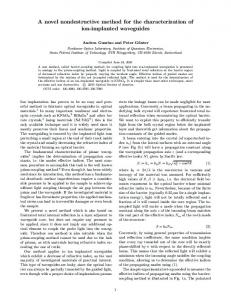
To assess the possibilities of DRS using two-energy method for substance discrimination by their effective atomic number, we carried out experiments using a graphite plate of 11 mm thickness (Z=6) and five aluminum plates (Z=13) of 1.5 mm thickness each. The possibilities of our developed software ensure visualization of color X-ray images on the basis of two images obtained in two different energy ranges. To attribute a color to an individual pixel of the two-energy image, two parameters are calculated: the total LED+HED signal, summing up the signals obtained in the low- and high-energy ranges, which characterizes the total level of attenuation of the X-ray radiation by the inspected object, and the ratio HED/LED, which characterizes the effective atomic number of the detected substance. To improve the resolution of “light” substances (with effective atomic number below 13) we carried out formation of two-energy images of the chosen inspected objects using different values of anode voltage (70 and 140 kV) and additional filtration (copper filter 0.75 mm at anode voltage 140 kV) – Fig.8.а). Then, with LED+HED values on the x axis, and HED/LED values on the y axis, we obtain, using the identification palette, the effective color of the image pixel. Using the data obtained, we analyzed averaged signal values in specified regions of the image in coordinates LED+HED, LED/HED. It can be seen from Fig.8,b,c that, depending on the total signal HED+LED, the HED/LED ratio characterizes the effective atomic number of the tested substance. The information thus obtained allows distinguishing one substance from another by the values of their effective atomic numbers. Higher accuracy in distinguishing between the substances by their effective atomic number can be reached using quasimonochromatic X-ray radiation [13] or a spectrometric RDC.
Proc. of SPIE Vol. 7805 78051P-6 Downloaded From: http://proceedings.spiedigitallibrary.org/ on 05/19/2015 Terms of Use: http://spiedl.org/terms
Using quasimonochromatic X-ray filters [13], it is possible to get close to the monochromatic case with identification of substances by their effective atomic number not dependent upon thickness [8,9,14]. With these filters, it is possible to obtain up to five fan-shaped beams of quasimonochromatic radiation from one X-ray source. This allows obtaining, in one scanning, up to five shadow X-ray images in different energy ranges, which, in turn, makes it possible to use the multi-energy method for determination of Zeff. This method can be considered as quasi-spectrometric. Also, it allows in principle detection of certain “heavy” elements with Z ≈ 50÷80 in the inspected objects (including gold, tungsten, gadolinium etc.).
а)
Al (5x1.5mm) Al (1.5mm) Graphite + Al (4x1.5mm) Al (5x1.5mm)
Air
Graphite + Al (4x1.5mm)
Graphite
b)
HED/LED
Graphite + Al (1.5mm)
HED+LED
c)
d)
Fig.8. Two-energy images of graphite plate of 11 mm thickness and aluminum plates of 1.5 mm thickness (a); average signal values in specific image areas in coordinates (HED/LED) vs. (HED+LED) (b); color identification palette (c); histogram of HED and LED signals (d).
For two-energy digital radiography, we carried out an experiment on determination of the best possible discrimination between substances by their effective atomic number. As inspected objects, we chose two substances with close effective atomic number values– water (Н2О), Zeff≈7.43, and glycerol (СН2ОНСНОНСН2ОН), Zeff≈ 6.87. To study the HED/LED ratio as function of the object thickness (characterized by HED+LED), we used small-sized polyethylene packages as containers for liquids. The use of such containers allowed obtaining X-ray images. To obtain the highest level of discrimination by Zeff , we obtained two shadow X-ray images of the tested objects. Large separation of the energies allowed reliable distinction between water and glycerol by their effective atomic numbers. In our measurements with 128- and 256-channel detectors, we used a Hamamatsu module with the following characteristics (Table 2):
Proc. of SPIE Vol. 7805 78051P-7 Downloaded From: http://proceedings.spiedigitallibrary.org/ on 05/19/2015 Terms of Use: http://spiedl.org/terms
Table 2. Characteristics of the module of S8865 series (Hamamatsu)
Module step, mm
Photosensitive area, mm2
Module length, mm
Spectral range, nm
0.4-0,2
0.3 х 0.6 0.15 х 0.3
51.2
200-1000
Photosensitivity peak, nm 720
Dark output voltage,mV 0.01
Output voltage, V 3.5
Sensitivity nonuniformity, % ±10
Working range of temperatures, °С −5 - +60
As a PD array, we used photodiode modules of S8865 (Hamamatsu, Japan) of the active type based on ССD structures. The block diagram of RDC is presented in Fig.9. arrays of photodiodes
to PC
arrays of charge-sensitive amplifiers
synchronization generator
RAM
displacement register
Fig.9. Block diagram of RDC
To lower the requirements to ADC fast response and speed of preliminary processing of all modules forming the detector array, signal processing is carried out in parallel. Data acquisition rate is rather low (time of read-out, processing and storage is ≈ 15 μs per one element - pixel). After photographic shooting, each RAM unit stores 1/8 of the image shot. Then, PC receives information on completion of the shot and, under control of the manager microprocessor, data from RAM are sequentially transferred to PC via USB port. From the acquired data (illuminance of the pixels), an image is synthesized, which is further processed using basic functions: scaling (magnification by 29 times), isolation of fragments, selection of required grades of gray from 4096 grades of the initial image, measurement of brightness at any point (12-digit grade of brightness, i.e., 4096 levels), construction of brightness profile, etc. The RDC software envisages a number of service functions – variation of density and contrast of the image, scaling, separation of fragments, image correction, etc. Thus, the model set of RDC based on multi-element arrays with different step ensures high quality solutions of nondestructive testing problems in different industrial applications. Fig.10 shows a shadow X-ray image of a standard metrological reference sample (wire pair of different diameter and gap) without absorber and with absorber in the form of steel plate.
а
б
Fig.10. Shadow X-ray image of standard metrological reference sample: a – without absorber, b – with absorber (steel plate of 10 mm thickness)
Proc. of SPIE Vol. 7805 78051P-8 Downloaded From: http://proceedings.spiedigitallibrary.org/ on 05/19/2015 Terms of Use: http://spiedl.org/terms
From general considerations, with a 256-channel detector with step of X-ray sensitive elements 0.2 mm it should be possible to obtain spatial resolution of 5÷6 line pairs/mm. The problem is that with detector apertures smaller than 0.8 mm (32-channel detector) substantial technical difficulties emerge in assembling the detector from elements; therefore, for 128- and 256-channel detectors the scintillator plate used should be not segmented, but solid. This, in turn, increases interference between channels, and even for 256-channel assemblies the obtained spatial resolution values were not better than 2,5 ÷3 line pairs/mm. Our further work will be directed towards optimization of material and thickness of scintillators to fully realize potential possibilities of such detectors. It can be concluded that X-ray detectors reported in this work can be successfully used for creation of fast DRS with improved SR. Their applications include welded joints, pipelines, fabricated metals and metalworks, as well as various objects with components made of materials with different effective atomic number.
REFERENCES [1] Ryzhikov, V.D., Opolonin O.D., Serhiy M. Galkin “Development of Receiving-Detecting Circuit for Digital Radiographic Systems with Improved Spatial Resolution”, Proc. SPIE 7450, 0J1-0J6 (2009). [2] Ryzhikov, V.D., Opolonin, O.D., Kozin, D.N., “X-ray radiation detectors of "scintillator-photoreceiving device" type for digital industrial radiography with improved spatial resolution,” Nuclear Instruments and Methods in Physics Research (A 505), 192-199 (2003). [3] Ryzhikov, V., Kozin, D.,Grynyov, B., “Scintillator-photodiod detectors for scanning introscopy with high special resolution”, Nuclear Instruments and Methods in Physics Research (A 505), 181-184 (2003). [4] Naydenov, S.V., Ryzhikov, V.D., Smith, C.F., “Multi-energy ZnSe-based radiography against terrorism: theory and experiments,” Proc. SPIE 6319, A1-A8 (2006). [5] Seminozhenko, V.P., Ryzhikov, V. D., Opolonin, A.D., “ZnSe(Te)-Based Crystals and Detectors for Nondestructive Testing and Cargo Inspection,” Proc. SPIE 6319, B-1-B-8 (2006). [6] Bavendiek, K., Ewert, U., Zscherpel, U., Meade, “New Digital Radiography Procedure Exceeds Film Sensitivity Considerably in Aerospace Applications” Proc.9-th Europian Conference on NDT, 44-48 (2006). [7] Grinyov, B.V., Ryzhikov, V.D., SeminozhenkoV.P., [Scintillation detectors and radiation monitoring systems on their base], Naukova Dumka, Kyiv, 447 (2007). [8] Ryzhikov, V., Grynyov, B., Opolonin, A., “Scintillation materials and detectors on their base for non-destructive two-energy testing”, Radiation Measurements (42), 915– 920 (2007) [9] Scherbakov, V.I., Grezdov, G.I.., [Electronic circuits on operational amplifiers], Tekhnika, Kyiv, 280(1983). [10] Naydenov, S.V., Ryzhikov, V.D., Smith,C.F., “Radiographic spectroscopy of composition of materials: a multienergy approach” Proc. IEEE Nuclear Science Symposium, 119-125 (2004). [11]Naydenov, S.V., Ryzhikov, V.D., “Determining Chemical Compositions by Method of Multi-Energy Radiography”, Technical Physics Letters 28(5), 357-360 (2002). [12]Grinyov, B., Ryzhikov, V. and Lecoq, P., “Dual-energy radiography of bone tissues using ZnSe-based scintielectronic detectors,” Nuclear Instruments and Methods in Physics Research, (A 571), 399–403 (2007) [13]http://www.mxftech.com/ [14]Naydenov, S.V., Ryzhikov, V.D. and Seminozhenko,V.P., “Multi-energy approach in non-destructive testing of functional materials,” Reports of NANU (11), 95-100(2002).
Proc. of SPIE Vol. 7805 78051P-9 Downloaded From: http://proceedings.spiedigitallibrary.org/ on 05/19/2015 Terms of Use: http://spiedl.org/terms