plied during the development of a wireless LAN application. The target of the ... Using this validation methodology, the prototype of the HIPERLAN/2 modem has ...
A Multi-level Validation Methodology for Wireless Network Applications* C. Drosos, L. Bisdounis, D. Metafas, S. Blionas, and A. Tatsaki INTRACOM S.A. 19.5 Km Markopoulo Ave., GR-19002 Peania, Athens, Greece {cdro,lmpi,dmeta,sbli,atat}@intracom.gr
Abstract. This paper presents the validation methodology established and applied during the development of a wireless LAN application. The target of the development is the implementation of the hardware physical layer of the HIPERLAN/2 wireless LAN protocol and its interface with the upper layers. The implementation of the physical layer (modem) has been validated in two different levels. First, at the functional level, the modem was validated by a high-level UML model. Then, at the implementation level, a new validation framework drives the validation procedure at three different sub-levels of design abstraction (numerical representation, VHDL coding, FPGA-based prototyping). Using this validation methodology, the prototype of the HIPERLAN/2 modem has been designed and validated successfully.
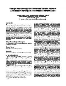
1 Introduction In wireless data communications there have been many standardization efforts in order to meet the increased needs of users and applications. In the 5 GHz band, there are the IEEE 802.1a [1] and the HIPERLAN/2 [2], both specified to provide data rates up to 54 Mbps for wireless LAN applications in indoor and outdoor environments. The market for these applications is growing rapidly and it is estimated to reach more than 61 million wireless products shipments by 2006 [3]. Both aforementioned standards operate in the same frequency band, and utilize orthogonal frequency division multiplexing (OFDM) for multicarrier transmission [4]. The purpose of this paper is to present a new multi-level validation methodology that was applied during the development of a HIPERLAN/2 modem. For the development of this modem an innovative flow was followed. This flow is based on the use of UML and its modeling capabilities for the high-level design and validation of the system. The flow is presented graphically in Fig. 1. Furthermore, the presented flow offers significant support for the validation of the hardware parts of the system, and more specifically, the implementation of the physical layer (modem) at three different levels of design abstraction (mathematical analysis, HDL design, FPGA prototype). These increased levels of support are achieved through a validation framework that integrates the validation of the modem with the validation of the high-level system model and its validation. *
This work was partially supported by the IST-2000-30093 EASY project.
E. Macii et al. (Eds.): PATMOS 2004, LNCS 3254, pp. 332–341, 2004. © Springer-Verlag Berlin Heidelberg 2004
A Multi-level Validation Methodology for Wireless Network Applications
333
System Specification
High-level System Modelling
High-level System Validation Validation Framework Software Design
Hardware Design
Software Validation
Hardware Validation
System Integration and Validation
Fig. 1. Design and validation flow for the implementation of the HIPERLAN/2 system
Other proposed methodologies for telecommunication systems (such as the one presented in [5]) do not offer support for the validation of the modem's design at different levels of design abstraction (system model, mathematical analysis, HDL design, FPGA prototype), even if they propose UML for the modeling of the system, as in the design methodology presented in [6]. The use of UML for the modeling and validation of the modem, as it is proposed in this paper, boosts its development significantly and automates the validation process.
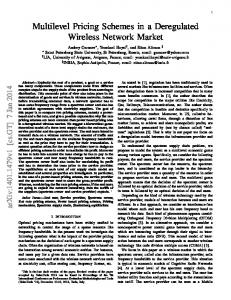
2 High-Level Modem Modeling The major problem in the design of a complicated system, such as a wireless LAN modem, is the verification of the design and the early detection of design faults [7]. For this reason a UML based flow for the system design of the modem was followed in order to produce an executable system specification (virtual prototype) for early verification of its control functions. This virtual prototype is based on a UML model, which uses the UML-RT profile [8]. The high-level model of the system (including the functionality of the modem) can be used to early validate the design of the HIPERLAN/2 system. The validation scenarios are based on the captured system-level use case and sequence diagrams. The structure of the UML based system model is presented in Fig. 2. Within the structure of the AP model there is a group of three objects that model the interface of the modem with the rest system, as well as the behavior of the mo-
334
C. Drosos et al.
E C L S en der
E C L R e c e iv e r
DUCC
M anagem ent and In itia liz a tio n E n tity
EC R e c e iv e r
ACF
EC S ender
S c h e d u le r
RLC
RRC
F ra m e B u ild e r
F ra m e D e c o d e r
M o d e m D a ta In te r fa c e
M o d e m C o n tr o l In te r fa c e
M o d e m B u r s ts C r e a tio n
Fig. 2. Object structure of the high level model of the HIPERLAN/2 system
dem’s control parts. These objects are the “modem data IF”, the “modem control IF”, and the “modem bursts creation”. The first object models the behavior of the data manipulation parts of the modem's interface (memories and registers), the second object models the behavior of the control parts of the interface (commands accepted by the modem, interrupts), while the third object models the behavior of the modem (creation of broadcast, downlink and uplink data bursts). The remaining objects inside the system structure (Fig. 2) are specific to the upper layers of the protocol stack and the custom implementation of the MAC layer and the error control mechanisms.
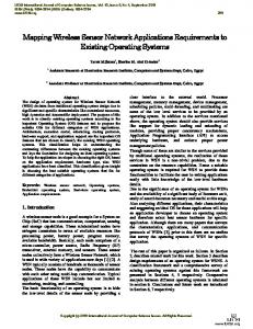
3 Modem’s Hardware-Software Mapping and Implementation An important task during the design of the modem is the mapping of its processes to the used instruction-set processors (i.e. software implemented processes) and to custom hardware (i.e. hardware implemented processes), as well as the determination of the interface of the processes implemented in software with those implemented in hardware. The mapping scheme that is used in this development is heuristic (based on our previous experience from similar systems' development). The architecture of the platform (ARM Integrator) in which the modem’s prototype is implemented was selected in order to realize the produced mapping scheme of the overall system. The prototype platform mainly consists of two ARM processor cores for the realization of the processes that were mapped for implementation in software, and FPGA
A Multi-level Validation Methodology for Wireless Network Applications
ARM CORE MODULE 1
335
ARM CORE MODULE 2 Modem Control processor
Protocol processor
SRAM
SRAM
AMBA BUS
BOTTOM LOGIC MODULE
TOP LOGIC MODULE
Modem functionality
SYSTEM CONTROL FPGA
Fig. 3. Block diagram of the system mapping on the ARM Integrator
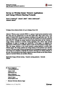
devices for the implementation of the hardware parts of the modem. The processor cores are responsible for the execution of the upper layers of the HIPERLAN/2 protocol stack and the software parts of the modem. The physical layer of the protocol (modem’s data path and control units) was implemented onto the FPGA devices of the prototype platform. Details on the architecture of the overall system implementing the HIPERLAN/2 wireless LAN standard can be found in [9], while the mapping of the system to the various elements of the selected architecture is presented in Fig 3. For the implementation of the interface between the modem and the HIPERLAN/2 DLC layer, a fully programmable hardware unit has been designed, capable of executing a set of suitable instructions. The selection of the instruction set of the modem is based on the results of alternative instructions sets using the high-level, UML based, virtual prototype of the system. The interface block of the modem is presented in Fig. 4. The interface of the modem’s hardware with the software parts of the modem includes a number of memory buffers, a number of interrupt signals and a command set. The command set of the modem includes suitable commands for transmission and reception of the various physical layer packets and commands for controlling the RF interface. Apart from the commands, the interface unit includes a number of storage buffers (e.g. command memory, transmit and receive data memories) and a series of interrupts (e.g. synchronization, end of receive, end of transmit), as acknowledgements to the protocol’s requests.
4 Validation Framework The validation of the design of the modem is performed in three different phases. The first one concerns the validation at the algorithmic level, where both receive and transmit algorithms of the modem are developed and verified at the numerical level. The second phase concerns the VHDL development environment and its simulator
336
C. Drosos et al. Bus interface Digital From modem
Symbol
Data in
Command Register
management
File
translator To modem
CRC
counter
To modem
Command
Status register generator EOB generation
Data out management
Puncturing Slot counter
Preamble Transmit Tx memory
Receive Rx memory _
Scrambler initialization
Memory address generator
Interrupt generator
To ARM
Fig. 4. Block diagram of the modem's interface
(modem design), while the third validation phase concerns the reconfigurable hardware and its accompanying platform (modem implementation). Before the validation of the modem’s algorithms, for the purposes of system validation, an executable specification model of the system has been developed, using UML. This model helps the validation of the specifications of the system early in the design process. An important artifact of the UML modeling is a set of system usage scenarios, captured formally using the UML’s modeling techniques. These usage scenarios, accompanied with sequence diagrams formally presenting each one, are a helpful resource for the validation of the system’s design at various levels of abstraction. This model is also used to validate the design of the system’s software, using as input the formally captured system specifications in the form of sequence diagrams. The novel approach to the validation of the hardware design of the system, and more specifically the modem, is to use the formal validation techniques offered by UML modeling for this purpose, and the developed UML model of the system. The idea is to use the same sequence diagrams and the same UML system’s model for the validation of the hardware blocks of the modem, suitably modified to meet the nature and specific requirements of hardware validation. The way to achieve this is to create a methodology and a validation framework that takes as its input usage scenarios from the system level and produces validation patterns for all the three modem’s validation phases. In order for the validation to be accurate, the transformation of the high-level usage scenarios to low-level test patterns for the validation of the modem has to be automatic and formal. In order to automate and facilitate the method for generating test input for all the three phases of the modem’s validation from the high-level system scenarios, a custom validation framework was developed. This framework provides an automatic connection of the whole system’s validation with the validation of the modem at the various phases of its development process. The operation of the developed framework is presented graphically in Fig. 5. Its major advantage is that from a given high-level frame description it can produce test patterns for the three validation phases that are consistent, and perform the same validation scenario at the corresponding validation environment.
A Multi-level Validation Methodology for Wireless Network Applications
337
Fig. 5. Modem's validation framework
As input to the validation framework, we use a description of the map of the HIPERLAN/2 frame at a high-level format. These descriptions are captured during the execution of the UML model of the system, under the stimulus of the usage scenarios in the form of sequence diagrams. During the execution of these testing scenarios by the UML system model the outputs of the scheduler class of the system are logged. These logs contain the maps for a selected number of MAC frames, as these maps have been generated by the central scheduler of the system and its policies for allocating transmission resources. The validation framework is able to process these types of high-level frame information to produce test patterns for all three phases of the modem's validation. The first phase of the validation of the modem concerns the validation of receive and transmit algorithms in a MATLAB environment. An ad-hoc testbench has been created inside this environment to validate the developed algorithms. This testbench can be driven by a simulation scenario file and data files containing data to be processed by the algorithms. All these types of files are generated automatically by the validation framework to efficiently validate the algorithms of the modem with the same operating scenarios as the ones used for the validation of the system’s UML model. The second validation phase supports the VHDL-based design of the modem. Inside the context of this phase, a VHDL-based testbench has been developed to help the verification task. The role of the validation framework during this phase is to produce input files and to support the operation of this VHDL-based testbench. More specifically, the framework produces force files that fill the memory blocks of the modem (configuration, transmit and control command memories) with valid contents, according to the high-level frame description. Furthermore, inputs and outputs of each algorithmic block are produced during the validation of the algorithms at the numerical level (MATLAB environment), which can also be used for the verification of the VHDL-based design, in direct comparison with the algorithmic results. The last phase of the modem’s validation concerns the FPGA-based prototype platform. The platform contains the reconfigurable blocks that realize the modem’s cir-
338
C. Drosos et al.
cuitry and the system’s processors. The validation phase at this platform is performed through the hardware-software interface of the modem, and is driven by the processor that is responsible for the modem control. The role of the validation framework during this phase is to produce automatically the processor source code that will drive the validation, by using the high-level frame description. The code must fill all modem’s memories with valid data specific to the validation scenario and control the execution of this scenario. In order to present the detailed operation of the validation framework and the functions that it performs in the context of the verification of the system’s algorithms, results from its application to the verification process of the wireless LAN modem are given below. The modem verification case presented here is based on an in-filed usage scenario, suitably modified to meet the specific validation environments used for the development of the algorithms. The scenario used for the testing of the modem design is a part of the protocol’s RLC association scenario, between the Access Point and the Mobile Terminal. A number of protocol frames are captured during this highlevel usage scenario and are translated into suitable test vectors for the verification of the modem. One of these frames is presented in Fig. 6, showing the bursts comprising a protocol frame, along with the starting time slot, duration, number of data units for each burst. The presented frame includes the broadcast burst (access point identity, capabilities and map of the current frame), the downlink burst (which contains a train of 5 short (SCH) and 12 long (LCH) packets), and the uplink burst (1 long and 10 short packets). Furthermore, the frame includes a random access burst, during which unassociated mobile terminals can perform their initial contact with the access point.
5 Validation Results In the timing diagrams of Fig. 6, the signal “AP_Tx_IQ_data_out” and “MT_Tx_IQ_data_out” are the transmitter’s output for the Access Point and the Mobile Terminal, respectively. The signals “AP_Rx_data_out” and “MT_Rx_data_ out” are the receiver’s output (the data that are inserted in the receive memory of the modem interface unit) for the Access Point and the Mobile Terminal, respectively. Also, the basic control signals for both Access Point and Mobile Terminal are shown (“data_valid”, enable and control commands for the receiver and start of transmission for the transmitter). Note, that analog interpretation of the data signals is used for better understudying of the results (data contained within the packets). Fig. 6 illustrates the simulated signals for a complete frame (broadcast, downlink and uplink bursts). These signals were generated after the execution of the simulation scenario that was produced automatically by the validation framework for the input frame depicted in Fig. 6. The different bursts of the simulated frame are clearly presented in the same figure. For each burst of the frame, the packets that it contains are also displayed in the same figure. For the transmission of the user packets (LCHs), this example uses QPSK 3/4 physical mode. Similar test cases were also performed in order to cover all the physical layer modes [10] supported by the HIPERLAN/2 standard. The complete set of the performed test cases is given in the following table, where the type and the number of data units for each burst are listed.
A Multi-level Validation Methodology for Wireless Network Applications
Fig. 6. Modem validation results
339
340
C. Drosos et al. Table 1. Modem’s test cases
6 Discussion and Conclusions This paper presents the validation of the software and hardware parts of the baseband modem for a wireless LAN application. For the design of the modem, a flexible implementation scheme was followed, where some parts of the modem were implemented in hardware, for efficiency reasons, and some parts in software, for flexibility reasons. The specialized communication between the hardware and the software parts of the modem was designed and validated by using the high-level model of the system. The functional validation of the modem and its interface was based on a high-level system model, developed using UML. This UML-based model of the HIPERLAN/2 system was validated using scenarios from real-life usage. The modem implementation was validated using an innovative validation framework. The framework uses as input a high-level frame format, as it has been produced by the simulation of the UML system model, and produces specific test patterns for the validation of the modem’s algorithms, at three different phases of the development (algorithmic, HDL, FPGA-based prototyping). The developed framework can be efficiently used for designing/validating wireless network applications. However, the application of the proposed methodology is not limited to wireless network applications, but can be applied in any embedded system development that incorporates telecommunication services. Current trends in System-on-Chip design tend to adopt UML as high-level modeling language; therefore, the proposed validation environment can be applied seamlessly to embedded system designs that are based on the use of UML. The main benefit of validation framework that was presented in this paper is that it integrates the validation of the modem’s development with the validation of the rest of the system, which is performed at a high level of abstraction using UML modeling. The use of this validation framework helps in the easy and efficient identification and correction of the modem's design errors. Furthermore, the proposed validation frame-
A Multi-level Validation Methodology for Wireless Network Applications
341
work is based on the modeling of the system with UML, which is becoming a trend in today's embedded systems [11]. The prototype of the presented HIPERLAN/2 modem was implemented successsfully on an FPGA-based platform (ARM Integrator). Furthermore, results from the co-simulation of the modem through the testing scenarios produced by the validation framework are also presented, along with sample outputs of the framework.
References 1.
The Institute of Electrical and Electronics Engineers (IEEE), ‘Supplement to IEEE standard for information technology – Telecommunications and information exchange between systems – Local and metropolitan area networks – Specific requirements – Part 11: Wireless LAN Medium Access Control (MAC) and Physical Layer in the 5 GHz band’, IEEE Std. 802.11a, (1999) 2. European Telecommunication Standards Institute (ETSI), Broadband Radio Access Network (BRAN): HIPERLAN Type 2: System Overview, TR 101 683, February 2000. 3. iSuppli Corp: "The future of wireless connectivity: Bluetooth and WLAN", Market analysis report, Q3 2002. 4. Van Nee, R., Prasad, R.: OFDM for mobile multimedia communications. Artech House, Boston, MA (1999) 5. Kneip, J., Weiss, M., Drescher, W., Aue, V., Strobel, J., Oberthur, T., Bole, M., Fettweis, G.: Single chip programmable baseband ASSP for 5 GHz wireless LAN applications, IEICE Trans. Electronics, Vol. 85 (2002) 359–367 6. Chen, R., Sgroi, M., Martin, G., Lavagno, L., Sangiovanni-Vincentelli, A., Rabaey, J.: Embedded System Design Using UML and Platforms, Proc. Forum on Specification and Design Languages, Marseille, France, 24-27 September, (2002) 7. Sangiovanni-Vincentelli, A., McGeer, P., Saldanha, A.: Verification of electronic systems, Proc. Design Automation Conf., Las Vegas, Nevada, 3-7 June (1996) 106-111 8. Selic, B., and Rumbaugh, J.: Using UML for Modeling Complex Real-Time Systems, Technical report, Rational Software (1998) 9. Bisdounis, L., Dre, C., Blionas, S., Metafas, D., Tatsaki, A., Ieromnimon, F, Macii, E., Rouzet, Ph., Zafalon, R., Benini, L.: Low-power system-on-chip architecture for wireless LANs, IEE Proc. Computers and Digital Techniques, Vol. 151 (2004) 2-15 10. Khun-Jush, J., Schramm, P., Wachsmann, U., Wegner, F.: Structure and performance of the HIPERLAN/2 physical layer, Proc. IEEE Vehicular Technology Conf., Houston, TX, 16-20 May (1999) 2667-2671 11. Martin, G.: UML for embedded systems specification and design: Motivation and overview, Proc Design Automation and Test in Europe Conf., Paris, France, 4-8 March (2002) 773-775