329
A Multi-Material Virtual Prototyping System for Product Development and Biomedical Engineering S. H. Choi1 and H.H. Cheung2 1
The University of Hong Kong,
[email protected] The University of Hong Kong,
[email protected]
2
ABSTRACT This paper proposes a multi-material virtual prototyping (MMVP) system that integrates the virtual reality (VR) and the layered manufacturing (LM) technologies for digital fabrication of heterogeneous multi-material prototypes for advanced product development and biomedical engineering. The system consists mainly of two algorithms for sequential and concurrent multitoolpath planning, and a virtual prototyping system. The algorithms adopt a topological hierarchysorting algorithm to establish the hierarchy relationship of multi-material slice contours for facilitating toolpath planning of multi-material layered manufacturing (MMLM). Subsequently, the sequential multi-toolpath planning algorithm generates sequential toolpaths that avoid redundant tool movements. To reduce build time further, the concurrent multi-toolpath planning algorithm generates collision-free concurrent toolpaths. Based on the hierarchy information, a bounding box can be adopted to approximate envelopes of contour families of the same material property to simplify detection of tool collisions. The algorithms are integrated to form the MMVP system for planning, stereoscopic simulation, and validation of multi-toolpaths for MMLM. Keywords: Multi-material layered manufacturing; sequential and concurrent multi-toolpath planning; virtual reality simulation; virtual prototyping.
1. INTRODUCTION Layered Manufacturing (LM) can fabricate a physical prototype from a 3D CAD model layer-by-layer without incurring expensive tooling costs. As high value-added products now often involve complex designs while surgical operations become more complicated, there are strong demands for multi-material prototypes, especially for advanced product development and biomedical applications. Multi-material prototypes can differentiate clearly one part from others, or tissues from blood vessels of a human organ; they perform better in rigorous environments than single-material prototypes. It is therefore desirable and timely to develop the multi-material layered manufacturing (MMLM) technology for fabrication of multi-material prototypes [1]. MMLM technology provides a relatively convenient way for fabricating multi-material parts, such as electronic products, advanced communication components, drug delivery devices, and innovative cellular and cell-containing tissue scaffolds [2, 3]. Although its benefits have been widely recognised, practical MMLM machines have yet to be developed, particularly for fabrication of relatively complex objects. In general, an MMLM machine may mainly consist of two sub-systems namely: (i) a hardware material-depositing mechanism, and (ii) a computer software system for processing complex slice contours to plan multi-toolpaths that control the material deposition mechanism. Some researchers have developed experimental MMLM machines for relatively simple objects. Lappo et al. [4] developed a Discrete Multiple Material Selective Laser Sintering (M2SLS) machine for fabrication of prototypes with discrete multiple materials. Evans and Yang [1] proposed a multi-component powder-dispensing device for Selective Laser Sintering (SLS) to make parts of 3D functional gradients. Jafari et al. [5] extended the Fused Deposition Modelling (FDM) hardware mechanism to form a Fused Deposition of Multiple Ceramics (FDMC) machine that could deposit up to four different materials in a layer of a multi-material ceramic part. However, an intelligent control software system would be required to deposit more materials. Cho et al. [6] reported a 3D Printing (3DP) machine developed in the Massachusetts Institute of Technology (MIT) that contained a multiple nozzle print-head mechanism for fabrication of objects with Local Composition Control (LCC), such as drug delivery devices and gradient index Computer-Aided Design & Applications, Vol. 2, Nos. 1-4, 2005, pp 329-338
330
lenses. For biomedical products, a Multi-nozzle Deposition Manufacturing (MDM) system was proposed for direct fabrication of tissue-engineering scaffold with gradient 3D structure [7]. Some companies have also attempted to produce commercial MMLM machines. Examples include FDMM and MP [8] for electroceramic components, and DMDTM [9] and LENSTM [10] for tooling parts and mould cavities. These systems are among the pioneering work, although they could only handle relatively simple parts of a limited variety of materials. Indeed, they can be adapted for further development of the hardware material-depositing mechanism. However, a viable computer software system for MMLM has yet to be developed. To address the software issue, some researchers have proposed CAD representation schemes for heterogeneous objects to provide geometric and material information needed for fabrication of multi-material prototypes [11, 12]. Qiu et al. [13] developed a CAD system to plan multi-toolpaths for MMLM of relatively simple objects. Nevertheless, it is crucial to develop an integrated software system to process complex objects for practical applications of MMLM. The system should be able to process complex multi-material slice contours, which are subsequently sorted and intra-connected to relate specific slice contours to a particular tool, such that the area is appropriately deposited with the desired material. This facilitates effective control of tools to deposit the selected materials at the appropriate contours, and to avoid redundant movements and possible collisions of the tools that move otherwise independently to increase efficiency. 2. THE PROPOSED MMVP SYSTEM This paper proposes a multi-material virtual prototyping (MMVP) system for digital fabrication of heterogeneous multimaterial prototypes to facilitate advanced product development and biomedical applications. The MMVP system addresses the key software issue of MMLM; it may be adapted as an intelligent control software system for practical and viable MMLM machines. It consists mainly of two topological hierarchy-based algorithms for sequential and concurrent multi-toolpath planning, and a virtual prototyping system for digital fabrication of multi-material prototypes. The sequential multi-toolpath planning algorithm generates sequential toolpaths without redundant tool movements. The algorithm is based on a topological hierarchy-sorting algorithm that establishes an explicit topological hierarchy relationship and a parent-and-child list of the complex slice contours, and subsequently arranges the contours in an appropriate sequence that facilitates multi-toolpath planning for MMLM by avoiding redundant movements. As a result, build time can be shortened accordingly. The concurrent multi-toolpath planning algorithm may reduce build time further, particularly for relatively large and complex objects. Based on the hierarchy information, the contours are sorted into contour families. Subsequently, work envelopes of contour families of the same material property are approximated by bounding boxes to facilitate tool collision detection, resulting in significant simplification of computation. Consequently, concurrent toolpaths can be effectively planned. These multi-toolpath planning algorithms are implemented and integrated with a virtual prototyping system to form the proposed MMVP system, which simulates MMLM processes to provide stereoscopic visualisation of the resulting digital multi-material prototypes for quality analysis, and process optimisation. Using the MMVP system, the designer can improve the prototype quality before physical fabrication by optimising the process parameters, such as layer thickness, hatch space, and build direction. With this approach, the lead-time and the cost of product development can be reduced significantly. The following sections describe the topological hierarchy-based multi-toolpath planning algorithms and the virtual prototyping system. Case studies are given in Section 3 to demonstrate possible applications of the MMVP system. 2.1 Topological Hierarchy-Based Multi-Toolpath Planning for MMLM 2.1.1 Sequential Multi-Toolpath Planning
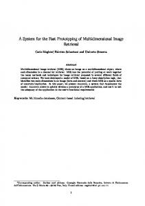
Multi-toolpath planning for MMLM requires geometric and material information of a part. As shown in Fig 1a, a layer of a skateboard consists of six materials, namely from m1 to m6. Based on such raw, random contours, there will be redundant tool movements. In order to reduce build time, six nozzles, namely from N1 to N6, should be appropriately controlled to deposit materials from m1 to m6 respectively on the related contours without redundant movements. To achieve this, a topological hierarchy-sorting algorithm is used to establish the explicit topological hierarchy relationship that represents the connectivity of the external contours and the internal cavities, as shown in Fig. 1b. A parent-andchild list is built to define the containment relationship of the contours. Hence, five entities, namely C10, C12, Computer-Aided Design & Applications, Vol. 2, Nos. 1-4, 2005, pp 329-338
331
C3→C4→C2→C1→C5, C8→C9→C7→C6→C13, and C11, are formed accordingly. Based on this information, the entities are sorted into nine contour families, namely C10 (Family 1), C12 (Family 2), C3→C4 (Family 3), C2→C1 (Family 4), C5 (Family 5), C8→C9 (Family 6), C7→C6 (Family 7), C13 (Family 8), and C11 (Family 9), are formed. Subsequently, the nine contour families of the skateboard layer are treated as nine independent inputs to generate nine sets of hatch vectors that define the multi-toolpaths accordingly. Thus, nine toolpaths (PC10, PC12, PC3,4, PC2, 1, PC5, PC8,9, PC7,6, PC13, and PC11) for the nozzles to deposit the respective materials are generated. Slicing plane
Build direction Z
Y
Material
m1 m2 m3 m4 m5 m6
X Slicing
C10
C11
C12 C9
C6 C8 C13
Name
C4
C2
C7
C1
C3 C5
Fig. 1a. A layer of contours of a multi-material toy skateboard.
Topological hierarchy relationship of contours Parent-and-child list for contour containment Level 0
C10
C12
C3
C8
Entity 1 Entity 2
Level 1
C4
C9
Level 2
C2
C7
Level 3
C1
C6
C5
C13
Level 4
C11 Entity5
Contour Families 1. C10 2. C12 3. C3→C4 4. C2→ C1 5. C5 6. C8→C9 7. C7→ C6 8. C13 9. C11
Toolpaths Material PC10 PC12 PC3,4 PC2, 1 PC5 PC8,9 PC7,6 PC13 PC11
m1 m2 m3 m4 m5 m3 m4 m5 m6
Entity 3 Entity4
Fig. 1b. Topological hierarchy relationship of contours.
In order to avoid redundant tool movements, the nine toolpaths should be further arranged based on the specific geometric and material information of each contour. For instance, PC3,4 and PC8,9 are grouped into a toolpath-set {S3(PC3,4→PC8,9)}, which is associated with nozzle N3 because contour families 3 and 6 are of material m3. In the same way, PC10, PC12, PC2,1 and PC7,6, PC5 and PC13, and PC11 are grouped into {S1(PC10)}, {S2(PC12)}, {S4(PC2,1→PC7,6)}, {S5(PC5→PC13)}, and {S6(PC11)}, which are associated with N1, N2, N4, N5, and N6, respectively. After associating with the related nozzles, the toolpath-sets are arranged in a sequence of S1→S2→S3→S4→S5→S6 according to the hierarchy levels of the contours. As a result, practical sequential multi-toolpaths can be conveniently generated, and the
Computer-Aided Design & Applications, Vol. 2, Nos. 1-4, 2005, pp 329-338
332
movement sequence of the nozzles is given as N1→N2→N3→N4→N5→N6. The sequential multi-toolpaths reduce build time by avoiding redundant tool movements, as shown in Fig. 2. Step 1: N1 deposits m1 on the related contours, and then returns to the datum position.
Step 2: N2 deposits m2 on the related contours, and then returns to the datum position.
Step 3: N3 deposits m3 on the related contours, and then returns to the datum position. N2 :{S3(PC3,4→PC8,9)}
N1 :{S1(PC10)} N2 :{S2(PC12)}
N6 :{S6(PC11)}
N5 :{S5(PC5→PC13)}
N4 :{S4(PC2,1→PC7.6)}
Step 6: N6 deposits m6 on the related contours, and then returns to the datum position.
Step 5: N5 deposits m5 on the Step 4: N4 deposits m4 on the related contours, and then related contours, and then returns to the datum position. returns to the datum position. Fig. 2. Sequential multi-toolpaths without redundant tool movements.
2.1.2 Concurrent Multi-Toolpath Planning
Build time can be reduced further, particularly for relatively large and complex prototypes, by depositing specific materials on the related contours of different materials simultaneously. However, planning of concurrent multitoolpaths requires detection of tool collisions, which may occur when the tools move at the same time. To detect and avoid tool collisions, an axis-aligned bounding box is adopted to approximate the area covered by a toolpath-set. The size of a nozzle, Ni, is assumed circular of radius RNi, which is offset outwards from the bounding box to form a work envelope for the nozzle. A work envelope is an area in which only the related nozzle is allowed to move. Potential tool collisions may now be detected by overlap tests of envelopes by checking the minimum separation distances between all pairs of envelopes. If the minimum separation distance between two envelopes is larger than zero, the two nozzles can move concurrently in their respective envelopes without collision. Hence, the number of overlap queries is given
1 n ( n − 1) , where n is the number of toolpath-sets in a layer. In comparison, the number of queries without 2 1 topological hierarchy relationship is O m ( m − 1) , where m is the total number of individual contours of a layer. 2 by O
Since n is generally much smaller than m, the proposed algorithm simplifies collision detection considerably. Fig. 3 shows the work envelopes of nozzles in Fig.1a. Six axis-aligned bounding boxes, namely from B1 to B6, for the toolpath-sets from S1 to S6 and six work envelopes, namely from E1 to E6, for six nozzles from N1 to N6, are formed. It is observed that N1, N2, N3, and N6 cannot move concurrently since there are overlapping between some of these nozzles work envelopes. In addition, N3, N4, and N5 cannot move simultaneously because E5 is in both E3 and E4 while E3 encloses E4. In such cases, it is not necessary to perform any overlap tests on envelopes E3, E4, and E5 since their containment relationships, C3→C4→C2→C1→C5 and C8→C9→C7→C6→C13, have already established in the topological hierarchy. Thus, the number of overlap queries,
1 O n ( n − 1) , can be further reduced. 2
Computer-Aided Design & Applications, Vol. 2, Nos. 1-4, 2005, pp 329-338
333
E1, work envelope of nozzle N1 The bounding box (B1) of RN1 contour families C10 RN2
E6, work envelope of E2, work envelope of nozzle N6 nozzle N2 The bounding box (B6) of The bounding box (B2) of contour families C11 contour families C12
RN5 RN4 E5, work envelope of E4, work envelope of E3, work envelope of nozzle N5 nozzle N4 nozzle N3 The bounding box (B4) of The bounding box (B3) of contour families C2→C1 and contour families C3→C4 and C7→C6 C8→C9 RN3
RN6 The bounding box (B5) of contour families C5 and C13
Fig. 3. Work envelopes of nozzles for contours in Fig. 1a.
Nozzle
Name N1 N2 N3 N4 N5 N6
Subsequently, concurrent multi-toolpaths can be easily planned based on the result of overlap tests for the pairwise combinations of the six work envelopes. However, there may be many feasible groupings of concurrent tool movements depending on geometry of each slice if there is not an appropriate grouping and sorting the result of overlap tests. Therefore, an algorithm was developed to plan and generate sequence of concurrent movement of tools by grouping and sorting the result of overlap tests for each layer [14]. The resulting sequence of concurrent nozzle movements for the layer is shown in Fig. 4. Compared with the six steps in Fig. 2, the resulted tool movements as shown in Fig. 4 are reduced to five steps only, and build time is reduced accordingly. Indeed, as the model becomes larger and more complex, the reduction of build time resulting from concurrent multi-toolpath planning will be more prominent.
Step 1: N1 deposits m1 on the related contours, and then returns to the datum position. N1
Step 2: N2 deposits m2 on the related contours, and then returns to the datum position.
Step 3: N3 and N4 move concurrently, and deposit m3 and m4 on the related contours, respectively on the contours, and then return to the datum position.
N2 N3
N6
Fig. 4. Digital simulation of concurrent nozzle movements.
Step 5: N6 deposits m6 on the related contours, and then returns to the datum position.
N4
N5
Step 4: N5 deposits m5 on the related contours, and then returns to the datum position.
2.2 Digital Fabrication of Multi-Material Prototypes The algorithms above are integrated with a virtual prototyping system to form the proposed MMVP system for multitoolpath planning, simulation, optimisation, and visualisation of MMLM processes. Subsequently, when digital Computer-Aided Design & Applications, Vol. 2, Nos. 1-4, 2005, pp 329-338
334
fabrication of a prototype is completed, it can be superimposed on its STL model to identify the resulting dimensional deviations. The overall accuracy of the prototype can be highlighted by showing the maximum and the average cusp heights as shown in Fig. 5. Hence, the designer can perform quality analyses of prototypes iteratively without incurring much cost until an acceptable set of process parameters, such as build direction, layer thickness, and hatch space, are obtained. Green pins showing unacceptable deviation
Excessive materials
Fig. 5. Dimensional deviations of the skateboard prototype beyond design limit.
3. CASE STUDIES The following two case studies demonstrate some possible applications of the MMVP system in product development and biomedical engineering. 3.1 A Necklace Hong Kong is famous for jewellery products. In response to frequent market changes, most jewellery manufacturers have adopted CAD/CAM and LM systems. Thus, the MMVP system is particularly useful to help the jewellery industry reduce the lead-time and the cost of product development. Fig.6a shows a layer of a necklace that contains ninety contours to be made of fifteen materials. Fig. 6b lists the topological hierarchy relationship of the slice contours, which are sorted into five hierarchy levels. Based on the hierarchy and material information, fifteen toolpath-sets, namely from S1 to S15, are generated and are associated with fifteen nozzles, from N1 to N15, respectively. Each nozzle is assigned to deposit a specific material. To generate concurrent multi-toolpaths, fifteen work envelopes, namely from E1 to E15 for the nozzles from N1 to N15, respectively, are established. Subsequently, overlap tests of the envelopes from E1 to E15 are carried out to facilitate collision detections of concurrent movements of the nozzles from N1 to N15. Based on the result of overlap tests of the envelopes, six sequences of concurrent nozzle movements are generated. The complete multi-material digital prototype is shown in Fig. 7a. Designers can perform quality analysis through visualisation of the prototype and its superimposition of the necklace STL model. Fig. 7b shows that the necklace prototype is superimposed on its STL model, in which the excessive materials on the prototype are highlighted. The average and maximum cusp heights of the prototype, which are 0.260mm and 0.554mm, respectively, are calculated for evaluation of the overall accuracy of the prototype. Green pins and red pins are used to highlight unacceptable deviations exceeding 0.550mm and the maximum deviations, respectively. Therefore, using the MMVP system, the designers can perform quality analysis and iterate the prototyping process conveniently in the computer without incurring extra cost. Thus, an optimal combination of process parameters, such as the build direction, layer thickness, and hatch space, can be obtained for subsequent fabrication of physical prototypes. Computer-Aided Design & Applications, Vol. 2, Nos. 1-4, 2005, pp 329-338
335
Slicing plan
Build direction Z Y X
Slicing
Fig. 6a. A layer of multi-material slice contours of a necklace. Level 0
C1 C24 to C90
Level 1
C2
Level 2
C3 C4 C5 C6 C7 C9 C10 C11 C14 C15 C16 C17 C18 C19C20 C21 C22 C23
Level 3
C8
Level 4
C12 C13
Fig. 6b. Topological hierarchy relationship of the slice contours.
Red pins showing maximum deviations
Excessive materials
A complete digital multi-material prototype of the necklace
Stereoscopic view
Fig. 7a. Digital fabrication process of a multi-material necklace prototype.
Green pins showing unacceptable deviations Fig. 7b. Areas of the necklace with dimensional deviations beyond design limit.
Computer-Aided Design & Applications, Vol. 2, Nos. 1-4, 2005, pp 329-338
336
C12 Slicing plan
Build direction Z
C10 C11
Two implant teeth
C2 C1 C3
Y
X C4
C5
C8 C6
Slicing Material
Name m1 m2 m3 m4
C7 C9
Fig. 8. A slice of a human jaw with two implant teeth.
3.2 A Human Jaw Multi-material prototypes are helpful for doctors to study and plan surgical operations. Therefore, a model of a human jaw with tooth implants, as shown in Fig. 8, is used to illustrate how the MMVP fabricates digital prototypes for biomedical applications. A layer of the jaw containing twelve contours is to be made of four kinds of materials, namely m1, m2, m3, and m4. Four nozzles, namely N1, N2, N3, and N4, are assigned to deposit materials m1, m2, m3, and m4, respectively. Fig. 9a shows simulation of concurrent nozzle movements of the digital fabrication process of the jaw prototype in Fig. 9b. In addition, the jaw prototype is superimposed on its STL model to highlight the excessive materials and the dimensional deviations, as shown in Fig.9c. Step 1: N1 and N2 move concurrently, and deposit m1 and m2 on the related contours, respectively on the contours, and then return to the datum position. N1 N2
Step 2: N3 deposits m3 on the related contours and then returns to the datum position.
Step 3: N4 deposits m4 on the related contours and then returns to the datum position.
N3
Fig. 9a. Digital simulation of concurrent nozzle movements.
Computer-Aided Design & Applications, Vol. 2, Nos. 1-4, 2005, pp 329-338
N4
337
Excessive materials
Green pins showing unacceptable deviation
Red pins showing maximum deviation
Fig. 9c. Dimensional deviations of the jaw prototype beyond design limit. Stereoscopic view
A complete digital multimaterial jaw prototype Fig. 9b. Digital fabrication process of a multi-material jaw prototype.
4. CONCLUSION An MMVP system for digital fabrication of heterogeneous multi-material prototypes has been developed. The system integrates the VR and the MMLM technologies for advanced product development and biomedical applications. The MMVP system consists of a suite of algorithms for multi-toolpath planning, simulation, optimisation, and visualisation of MMLM processes. The topological hierarchy-sorting algorithm is used to process complex multi-material contours to establish the topological hierarchy relationship of the contours. Based on this, the sequential multi-toolpath planning algorithm can arrange the contours in an appropriate sequence to generate sequential toolpaths without redundant movements. To reduce build time further, the concurrent multi-toolpath planning algorithm can generate concurrent toolpaths. It first sorts the contours into contour families, and subsequently adopts an axis-aligned bounding box approach to approximate the area covered by the contour families with the same material property to facilitate detection of tool collisions. The MMVP system addresses the key software issue of MMLM; it may be adapted as an intelligent control software system for practical and viable MMLM machines. ACKNOWLEDGEMENT The authors would like to acknowledge the Research Grant Council of the Hong Kong SAR Government and the CRCG of the University of Hong Kong for their financial support for this project. 5. REFERENCES [1] Yang SF, Evans JRG. A multi-component powder dispensing system for three dimensional functional gradients. Materials Science & Engineering A 2004; 379(1-2):351-359.
Computer-Aided Design & Applications, Vol. 2, Nos. 1-4, 2005, pp 329-338
338
[2]
[3] [4]
[5] [6] [7] [8] [9] [10] [11]
[12] [13] [14]
Safari A, Cesasrano III J, Clem PG, Bender B. Fabrication of advanced functional electroceramic components by layered manufacturing (LM) methods. Proceedings of the 13th IEEE International Symposium on Applications of Ferroelectronics, Nara, Japan; 2002. p.1-6. Sachlos E, Reis N, Ainsley C, Derby B, Czernuszka JT. Novel collagen scaffolds with predefined internal morphology made by solid freeform fabrication. Biomaterials 2003; 24(8):1487-1497. Lappo K, Jackson B, Wood K, Bourell D, Beaman JJ. Discrete multiple material selective laser sintering (M2SLS): experimental study of part processing. In: Bourell DL, et al., editors, Austin, Texas. Solid Freeform Fabrication Symposium, Austin, Texas. The University of Texas; 2003. p.109-119. Jafari MA, Han W, Mohammadi F, Safari A, Danforth SC, Langrana N. A novel system for fused deposition of advanced multiple ceramics. Rapid Prototyping Journal 2000; 6(3):161-175. Cho WJ, Sachs EM, Patrikalakis NM, Troxel DE. A dithering algorithm for local composition control with threedimensional printing. Computer-Aided Design 2003; 35(9):851-867. Yan YN, Xiong Z, Hu YY, Wang SG, Zhang RJ, Zhang C. Layered manufacturing of tissue engineering scaffolds via multi-nozzle deposition. Materials Letters 2003; 57(18):2623-2628. Bremnan RE, Turcu S, Hall A, Hagh NM, Safari A. Fabrication of electroceramic components by layered manufacturing (LM). Ferroelectrics 2003; 293(1): 3-17. http://www.pom.net/ http://mfgshop.sandia.gov/1400_ext/1400_ext_LENS.htm Kumar V, Rajagopalan S, Cutkosky M, Dutta D. Representation and processing heterogeneous objects for solid freeform fabrication. Sixth IFIP WG 5.2 International Workshop on Geometric Modelling: Fundamentals and Applications, Tokyo, Japan. The University of Tokyo; 1998. Morvan SM, Fadel GM. Heterogeneous solids: possible representation schemes. In: Bourell DL, et al., editors, Austin, Texas. Solid Freeform Fabrication Symposium, Austin, Texas. The University of Texa; 1999. p.187-198. Qiu D, Langrana NA, Danforth SC, Safari A, Fafari M. Intelligent toolpath for extrusion-based LM process. Rapid Prototyping Journal 2001; 7(1):18-24. Cheung HH. A multi-material virtual prototyping system. MPhil Thesis. The University of Hong Kong, 2004.
Computer-Aided Design & Applications, Vol. 2, Nos. 1-4, 2005, pp 329-338