Available online at www.sciencedirect.com
ScienceDirect Procedia CIRP 52 (2016) 251 – 256
Changeable, Agile, Reconfigurable & Virtual Production
A multi-objective design approach to include material, manufacturing and assembly costs in the early design phase. Claudio Favia*, Michele Germania, Marco Mandolinia a
Department of Industrial Engineering and Mathematical Sciences , Università Politacnica delle Marche, via Brecce Bianche 12, 60131 Ancona, Italy
* Corresponding author. Tel.: +39-071-2204880; Fax: +39-071-2204801. E-mail address:
[email protected]
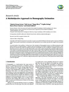
Abstract Conceptual design is a crucial activity in the product development process. The design freedom must consider a trade-off analysis among several aspects such as assembly, manufacturing, and costs. The goal of this approach is to define a multi-objective design approach for the determination of feasible design options. The approach is grounded on the concept of functional basis for the analysis of product modules and the theory of Multi Criteria Decision Making (MCDM) approach for the assessment of the best design option. A complex product (tool-holder carousel of a machine tool) is used as a case study to validate the approach. © Published by Elsevier B.V. This © 2016 2016The TheAuthors. Authors. Published by Elsevier B.V.is an open access article under the CC BY-NC-ND license (http://creativecommons.org/licenses/by-nc-nd/4.0/). Peer-review under responsibility of the scientific committee of the Changeable, Agile, Reconfigurable & Virtual Production Conference. Peer-review under responsibility of the scientific committee of the Changeable, Agile, Reconfigurable & Virtual Production Conference 2016 Keywords: Conceptual design, multi-objective design, complex products, design for assembly.
1. Introduction Different Design-for-X (DfX) methods have been developed in recent years to aid designers during the design process and in the product engineering stage. Methods for efficient Designfor-Assembly (DfA) are well-known techniques and widely used throughout many large industries. DfA can support the reduction of product manufacturing costs and it provides much greater benefits than a simply reduction in assembly time [1] [2]. However, these methods are rather laborious and in most cases, they require a detailed product design or an existing product/prototype. Other approach investigates the product assemblability starting from the product functional structure [3] [4]. In this way, the DfA technique can be applied during the conceptual design phase when decisions greatly affect production costs. Even so, the conceptual DfA, as the authors call their method, do not consider manufacturability aspects such as the material selection or the most appropriate process to build up components and parts. Furthermore, product design and optimization is a multi-objective activity and not only limited to the assembly aspects.
In this context, this paper proposes an improvement to overcome the above mentioned weak points and to optimize the product assemblability as well as the parts manufacturability by taking into account the best cost-effective technical solutions. The step beyond the current state of the art is the possibility to optimize both assembly and manufacturing in the early design stage when the product model is not yet available and defined. The main goal of this work is to define a multi-objective design approach which aims to have a comprehensive analysis of the manufacturing aspects (including assembly, materials, processes, costs and times). This is particularly important to avoid design solutions which can be excellent, for example, from the assembly point of view but not cost-efficient in terms of manufacturing costs and investments. The novelty of this approach is to make systematic a random process which is currently based on the company know-how and experiences. Moreover, the mathematical model makes the approach repeatable and applicable in any manufacturing context. §2 reports a brief review of the research background. §3 reports in detail the steps of the approach. A case study (toolholder carousel) is analysed in §4. Results discussion and concluding remarks are reported in §5.
2212-8271 © 2016 The Authors. Published by Elsevier B.V. This is an open access article under the CC BY-NC-ND license (http://creativecommons.org/licenses/by-nc-nd/4.0/). Peer-review under responsibility of the scientific committee of the Changeable, Agile, Reconfigurable & Virtual Production Conference 2016 doi:10.1016/j.procir.2016.07.043
252
Claudio Favi et al. / Procedia CIRP 52 (2016) 251 – 256
2. Research background on target design methodology and multi-objective design The design stage is a long and iterative process for the development of certain products. Design stage activities can be divided into four main phases: (i) Problem definition and customer needs analysis, (ii) Conceptual design, (iii) Embodiment design, and (iv) Detail design. In the first phase, customer requirements are collected and analyzed, then, the requirements are translated into product features, and finally, concepts that can satisfy the requirements are generated and modelled [5]. It is well-known that, although design costs consume approx. 10% of the total budget for a new project, typically 80% of manufacturing costs are determined by the product design [6] [7]. Manufacturing and assembly costs are decided during the design stage and their definition tend to affect the selection of materials, machines and human resources that are being used in the production process [8]. DfA is an approach which gives the designer a thought process and guidance so that the product may be developed in a way which favors the assembly process [9]. In the industrial practice, the Boothroyd and Dewhurst (B&D) is one of the most diffused DfA approach [2]. Different design solutions can be compared by evaluating the elimination or combination of parts in the assembly and the time to execute the assembly operations [10]. Usually, DfA methods are applied in the detailed design phase when much of the design process has been deployed and solutions have been identified [11]. This is the main drawback of this approach. Stone et al. [3] define a conceptual DfA method in order to support designers during the early stages of the design process. The approach uses two concepts: the functional basis and the module heuristics [12]. The functional basis is used to derive a functional model of a product in a standard formalism and the module heuristics are applied to the functional model to identify a modular product architecture [13]. The approach has two weak points: (i) the identification of best manufacturing process for part production and (ii) related cost-efficient material. The selection of the most appropriate manufacturing process is dependent on a large number of factors but the most important considerations are shape complexity and material properties [14]. According to Das et al. [15], Design-forManufacturing (DfM) is defined as an approach for designing a product which: (i) the design is quickly transitioned into production, (ii) the product is manufactured at a minimum cost, (iii) the product is manufactured with a minimum effort in terms of processing and handling requirements, and (iv) the manufactured product attains its designed level of quality. DfA and DfM hardly integrate together, and the Design-forManufacturing-and-Assembly (DfMA) procedure can typically be broken down into two stages. Initially, DfA is conducted, leading to a simplification of the product structure and economic selection of materials and processes. After iterating the process, the best design concept is taken forward to DfM, leading to detailed design of the components for minimum manufacturing costs [16]. Cost estimation is concerned with the predication of costs related to a set of activities before they have actually been executed. Cost estimating or Design-to-Cost (DtC) approaches
can be broadly classified as intuitive method, parametric techniques, variant-based models, and generative cost estimating models [17]. However, the most accurate cost estimates are made using an iterative approach during the detail design phase [18]. While DtC is usually applied at the embodiment design or even worse in the detail design phase, to be efficient DtC requires to be applied at the same time of DfMA (conceptual design phase) [19] [20]. In this way, DtC is only an optimization of an already selected design solution from the manufacturing/cost point of view. The only way to overcome the aforementioned issues is the multi-objective approach which takes into account all the production aspects (assemblability, manufacturability, materials, costs, etc.) at the same time. Different mathematical models can be used as a solver for the multi-objective problem. Multi Criteria Decision Making (MCDM) approach is one of the common approach for multi-objective problems [21]. Novelty of the proposed approached is based on the application of MCDM in the conceptual design phase to account multiple production aspects in the development of complex products. 3. The multi-objective conceptual design approach The first step of the proposed approach is a standard practice in the conceptual design phase, that is the set out the product modules and properties considering the functional basis and the module heuristics. Then, by the concept of morphological matrix, a list of possible and feasible design solutions can be pointed out in order to fulfill the rows of the morphological matrix for each specific module. This step can be assisted and carried out using the company knowledge and the skills of designers and engineers. Finally, considering the multiobjective approach (DfA, DfM and DtC) based on the MCDM (Multi Criteria Decision Making) theory, suggestions for the product structure simplification and for the selection of economic materials and manufacturing processes are stated. Fig. 1 shows the workflow of the proposed multi-objective design approach in relation to the standard practice of DfA. It is important to highlight that the proposed approach is able to consider different target design methodologies (DfX) early in the conceptual design of product development process and not in the embodiment design or even worse in the detail design phase. In particular, the focus of this research work is related to the production (assembly, manufacturing, material selection and cost) aspects. The steps of the proposed approach are detailed here below.
3.1. Step 1: Product modules definition and related properties Through functional analysis and module heuristic approach, it is possible to determine the number of functions which identify a product and the related flows (energy, material and signal). The functional analysis is able to break up the product in its constituent functions as a first step of design process. This is the first step of the conceptual design and helps designers and engineers in the definition of the product functions as well as in the identification of the overall product structure. The module heuristic identifies the in/out flows of each function.
Claudio Favi et al. / Procedia CIRP 52 (2016) 251 – 256
Fig. 1. Flow diagram of the proposed multi-objective conceptual design approach and the comparison with the DfA approach.
By using this approach, it is possible to translate the product functions into functional modules. Functional modules define a conceptual framework of the product and the initial product configuration. A one-to-one mapping between product functions and modules is expected, but it can be possible that several functions are developed only by one physical module. Furthermore, heuristics allow determining the specific properties of each functional module. Attributes and properties need to be defined for each module in order to identify the technical and functional aspects which must be guaranteed as well as a basis for the definition of the feasible and not-feasible design solutions.
costs and productivity. Designers skills, suppliers and stakeholders’ surveys as well as well-structured and updated knowledge repositories can help in the definition of the design options suitable to implement the module under investigation and for the population of the morphological matrix. The morphological matrix finally shows existing alternative design options for each functional module of a complex system and it permit a rapid configuration of the product with the selection of the best option for a specific module. Design options must be reliable and compliant with the properties defined in the module definition.
3.3. Step 3: Multi-objective analysis 3.2. Step 2: Design solutions definition The transition from product modules to potential design solutions (components or sub-assemblies) is based on the knowledge of specific properties identified during the generation of the product modules. A very helpful tool at this step is the morphological matrix which can improve the effectiveness of the conceptual analysis and translates functional modules to physical modules such as sub-assemblies or components. A morphological matrix is traditionally created by labelling each line with all the identified products’ modules and, for each module, the possible design options, listing the solutions as columns and the product’ modules as rows [22]. In a manual engineering design context, the morphological matrix is limited to the concepts generated by the engineer, although the morphological matrix is one technique that can be used in conjunction with other design activities (brainstorming processes, company knowledge analysis, designer’s skills and attitude to problem solving, etc.) [23]. In particular, the alternative design options are developed and analyzed based on the concepts of DfA, DfM and DtC to retrieve, at conceptual level, the best configuration in terms of
The multi-objective analysis is the core of the proposed approach and aims to give a trade-off among different aspects of industrial production, such as assembly, materials and manufacturing processes taking into account the overall cost as a driver for the optimization process. The multi-objective analysis is following the product modules definition and the classification of design solutions, but it is still part of the conceptual design phase. In fact, in this phase are available only general information and not specific details about geometry, shape, manufacturing parameters, material designation, etc. Design options, retrieved in the previous step, are analysed based on rough cost estimation and based on designers’ and engineers’ knowledge. This is an iterative process, as highlighted in Fig. 1, in which all the design solutions are evaluated in order to retrieve useful suggestions for the development of the product and its constituent components. The best design concept is not the best assembly concept optimized considering the minimum cost for the parts manufacturing, but the optimal solution in terms of costs, assembly, material and manufacturing process considering for example the production rate (batch) and all the other product
253
254
Claudio Favi et al. / Procedia CIRP 52 (2016) 251 – 256
features. In this approach, the selection of the best design options is made using a MCDM (Multi Criteria Decision Making) method call TOPSIS (Technique for Order of Preference by Similarity to Ideal Solution). The TOPSIS was first developed by Hwang & Yoon and it is attractive in that limited subjective input (the only subjective input needed from decision makers is weights) [21]. According to this technique, the best alternative would be the one that is nearest to the positive ideal solution and farthest from the negative ideal solution [24]. The positive ideal solution is a solution that maximizes the benefit criteria and minimizes the cost criteria, whereas the negative ideal solution maximizes the cost criteria and minimizes the benefit criteria [25]. Using a TOPSIS method, the different design options, identified in the previous step, are ranked in order to choose the best module configuration which takes into account several aspects such as assemblability, manufacturability, materials and costs. The TOPSIS method is not time consuming due to the easy implementation in a common spreadsheet or in a dedicated software tool. Inputs required are only: (i) attributes weight (based on company targets and requirements) and (ii) scores for each design option in relation to the selected attributes (based on engineers expertizes and knowledge). Anyway, a sensitivity analysis of results is necessary to take into account the rates and weights of the evaluation. Finally, in the embodiment design phase, based on the conceptual design solution selected, properties and parameters are specifically defined such as the material (i.e. Al wrought alloy EN-AW6005 from the Aluminum alloy class) or the specific manufacturing process (High Pressure Die Casting 1200 [ton] from the Casting processes). Furthermore, process parameter optimization (the definition of the virtual model, the tuning of manufacturing process parameters, the arrangement of assembly lines, etc.) is pointed out by the traditional design tools (CAD, FEM, etc.). Afterwards, the detailed design is defined and physical prototypes are realized before to start the production phase. 4. Case study: A tool-holder carousel of a CNC machine A tool-holder carousel of a CNC machine tool for wood processing and machining has been analysed within this work as a case study. The tool holder carousel is a complex assembly as highlighted by the original design model proposed in Fig. 2.
On the basis of the functional analysis and the modular approach, several product modules have been identified in the conceptual design stage. The overall function of this complex system is “to feed the CNC machine tools with specific tool”. The functional analysis has general validity for this kind of product and can be used also as a conceptual analysis for other CNC machine models. Here below, two different modules of this product are proposed and analysed in detail: x The Bracket support for compressed air nozzle/photocell. x The carousel Grippers. As demonstrative example, in the following paragraphs, a complete re-design process has been carried out to compare, accurately, design alternatives after the conceptual design phase and so in the detail design phase. For this reason, complete 3D CAD models have been built up for a comprehensive and detailed analysis which can be considered as part of the method validation.
4.1. The Bracket support The Bracket support has the following function: “to support nozzle for compressed air and photocell”. The morphological matrix for the Bracket support is presented in Table 1. Several other design options are not stated in in the morphological matrix because they are not feasible considering the requirements and constrains defined during the properties definition. Table 1: Morphological matrix for the Bracket support. Design options for Bracket support #1 - Welded structure
#2 - Casting piece Al
Alternative design solutions have been analyzed following the multi-objective design approach and the MCDM methodology. The results of the MCDM analysis is reported below in Fig. 3. Moreover, in the Fig. 3 the weight and the score assessment have been reported. Rating scale ASSEMBLY MATERIAL MANUFACTURING COST
0 - not important 0 - not important 0 - not important 0 - not important
10 - very important 10 - very important 10 - very important 10 - very important
Weight 8 5 7 10
S1 S2 S1+S2 S2/(S1+S2) Best option
Fig. 2. Tool-holder carousel of a CNC machine tool.
#3 - Plastic piece
Fig. 3. MCDM analysis for the Bracket module.
Design options Welded Casting Plastic Structure piece Al piece 6 7 9 7 5 10 7 4 10 5 2 9 IDEAL SOLUTION (S1) 3.5 1.5 0.0 1.3 3.6 0.0 2.7 10.7 0.0 14.5 44.5 0.0 4.7 7.8 0.0 NEGATIVE IDEAL SOLUTION (S2) 0.0 18.9 3.5 0.6 0.0 3.6 2.7 0.0 10.7 8.2 0.0 44.5 3.4 4.3 7.9 4.7 7.8 0.0 3.4 4.3 7.9 8.1 12.1 7.9 0.42 0.36 1.00 1.00
Plastic piece
255
Claudio Favi et al. / Procedia CIRP 52 (2016) 251 – 256
The score of each attribute for each design option has been assigned based on the expertizes and knowledge of company engineers and designers supported by the R&D team. The Bracket support for compressed air nozzle and photocell has been traditionally made by steel plates bended and welded together to create the desired geometry. The Welded structure is an assembly solution which guarantees a good productivity without significant investment costs. Plastic piece is another possible solution for the Bracket realization which guarantee even better productivity and costefficiency considering a high production rate (approx. 2500 pieces in 10 years of production). This can be considered the best solution in terms of assemblability, as well as in terms of material class (low cost thermoplastics), equipment and manufacturing process (injection moulding). A CAD model of the two solutions have been built up and proposed in Fig. 4 for the comparison and the analysis.
Alternative design solutions have been analyzed following the multi-objective design approach and the MCDM methodology. The results of the MCDM analysis is reported below in Fig. 5. Moreover, in the Fig. 5 the weight and the score assessment have been reported. Rating scale ASSEMBLY MATERIAL MANUFACTURING COST
0 - not important 0 - not important 0 - not important 0 - not important
10 - very important 10 - very important 10 - very important 10 - very important
Weight 8 5 7 10
Design options Casting Casting Plastic piece Zn piece Al piece 9 9 6 8 6 10 7 7 9 8 5 9 IDEAL SOLUTION (S1) 0.3 0.0 0.0 2.5 2.9 0.7 2.9 0.0 3.3 1.5 1.5 0.0 23.8 1.0 15.2 0.0 5.5 1.8 4.4 1.6 NEGATIVE IDEAL SOLUTION (S2) 1.1 22.9 2.5 0.0 0.0 0.7 0.0 2.9 0.0 0.4 0.4 3.3 0.0 15.2 1.0 23.8 1.1 6.3 2.0 5.5 5.5 1.8 4.4 1.6 1.1 6.3 2.0 5.5 6.6 8.0 6.4 7.1 0.16 0.78 0.31 0.77
Machined pieces 8 6 6 4
S1 S2 S1+S2 S2/(S1+S2)
Best option 0.78 Casting piece Zn
Fig. 5. MCDM analysis for the carousel Grippers.
Fig. 4. CAD model of the two proposed design options (Welded structures vs. Plastic piece).
Moreover, it is important to highlight that the Plastic piece has several other advantages such as the possibility to easily assemble the air compressor tool and photocell (snap-fits vs. screws) as well as to fix other components which is currently considered as part of another module which are assembled with threaded elements (power unit control, etc.). Detail design analysis for the different design options highlights how the plastic piece is the most cost-efficient solution compared with the other options.
The carousel Grippers do not require particular structural properties but the necessity to be replaced due to possible damages or wear which can happening during their use. Each carousel has at least 16 Grippers and this means that the production rate of the Grippers is 16 times the production rate of the carousel itself (approx. 40000 pieces in 10 years of production). Die casting process and zinc alloy guarantee an excellent productivity and the use a rigid plastic material as a body cover (e.g. Acrylonitrile Butadiene Styrene - ABS) assures the wear resistance property and the grasp efficiency. This is an excellent solution in terms of assemblability and manufacturability (material, equipment and process) including the cost and the estimated batch. A 3D CAD model of the proposed solutions has been built up and analysed in detail for the approach validation (Fig. 6). Few design changes from the original design solution have been done to reduce the part complexity and the number of components.
4.2. The carousel Grippers The carousel Grippers have the following function: “to hold several tools during the machining operations and to feed the spindle with the proper tool”. The morphological matrix for the carousel Grippers is presented in Table 2. Several other design options are not stated in in the morphological matrix because they are not feasible considering the requirements and constrains defined during the properties definition. Table 2: Morphological matrix for the carousel Grippers. Design options for carousel Grippers #1 - Machining piece
#2 - Casting piece Zn
#3 - Casting piece Al
#4 - Plastic piece
Fig. 6. CAD model of the proposed design options (Casting piece Zn).
Detail design analysis for the different design options highlights how the die casting process of zinc alloy is the most cost-efficient solution compared with the other options. Even if the MCDM analysis pointed out that plastic piece has a similar score compared with the casting piece Zn (0.77 vs. 0.78) this solution is to prefer because can guarantee a better resistance to crack and to fatigue for this kind of component (lower replacement rate).
256
Claudio Favi et al. / Procedia CIRP 52 (2016) 251 – 256
5. Results discussion and concluding remarks The proposed work aims to develop a multi-objective design approach for a comprehensive analysis of the manufacturing aspects (assembly, materials, processes, costs and times) in the conceptual design phase. The approach is able to support engineering team in the selection of the optimal design solution during the early design phase of the product development process (conceptual design). The presented case study (toolholder carousel) is a good example to demonstrate the advantages of a multi-objective approach for decision-making during the early product design phase. An overview of the product results is presented in Table 3. Table 3: Main attributes comparison for the tool holder carousel before and after re-design. Number of components
Assembly time
Total Cost (material + manuf. + assembly)
Original Design
325 pcs.
88 min.
359.73
After re-design
123 pcs.
33 min.
225.74
Considering the modules analysed in detail in this work here below are reported the main results. For the Bracket support, the new design solution highlight not only a cost reduction based on material and related manufacturing process but also an easier assembly phase (less components, use of snap-fits, etc.). Furthermore, the support has been conceived to fix and to integrate other components which is currently considered as part of another module (power unit control, etc.). In this way a product simplification has been obtained. For the Carousel Grippers, the new developed solution consisting in a new shape for the body cover which is able to meet, at the same time, assembling, manufacturing and cost requirements, improving the design of the old solution. Obviously, a sensitivity analysis of the results is recommended due to the dependency between the result obtained and scores assigned during the evaluation. This issue does not limit the applicability of the approach but encourage to set weights based on the specific targets and to implement a sensitivity analysis to investigate the influence of each score for each attribute. Future perspectives on this topic will be a deeply validation of the method for other case studies and product typologies as well as the definition of a framework for the implementation of the proposed approach in a design tool. A step forward will be to include other interesting production aspects such as environmental impacts, machine energy consumptions, etc. References [1] De Fazio, T.L., Rhee, S.J., Whitney, D.E. Design Specific Approach to Design for Assembly (DFA) for Complex Mechanical Assemblies. In IEEE Robotics and Automation. 1999, 15(5), 869-881. [2] Boothroyd, G., Dewhurst, P., Knight, W. Product Design for Manufacture and Assembly, 2nd edition, 2002 (Marcel Dekker). [3] Stone, R.B., McAdams, D.A. A product architecture-based conceptual DFA technique. Design Studies, 2004, 25, 301-325.
[4] Favi, C., Germani, M. A method to optimize assemblability of industrial product in early design phase: from product architecture to assembly sequence. International Journal on Interactive Design and Manufacturing, 2012, 6(3), 155-169. [5] Pahl, G., Beitz, W. Engineering Design: A Systematic Approach. 2nd edition, 1996 (Springer). [6] Ulrich, K.T. and Eppinger, S.D. Product Design and Development, 3rd Edition, 2003 (McGraw-Hill Inc.). [7] Huang, Q. Design for X: Concurrent Engineering Imperatives, 1996 (Chapman and Hall). [8] Nitesh-Prakash, W., Sridhar V.G., Annamalai K. New Product Development by DfMA and Rapid Prototyping. Journal of Engineering and Applied Sciences. 2014, 9(3), 274-279. [9] Otto, K., Wood, K. Product design: techniques in reverse engineering and new product development, 2001 (PrenticeHall). [10] Samy, S.N., ElMaraghy, H.A. A model for measuring products assembly complexity. International Journal of Computer Integrated Manufacturing, 2010, 23(11),1015-1027. [11] Azman, Y., Nurnasran, P., Ruslizam, D., Mazni, O., Sharifah L.S.A. Product assembly sequence optimization based on genetic algorithm. International Journal of Computational Science and Engineering, 2010, 02(9), 3065-3070. [12] Stone, R.B., Wood, K.L., Crawford, R.H. A heuristic method for identifying modules for product architectures. Design Studies, 2000, 21, 5-31. [13] Dahmus, J.B., Gonzalez-Zugasti, J.P., Otto, K.N. Modular product architecture. Design Studies, 2001, 22(5), 409-424. [14] Estorilio, C., Simião, M.C. Cost reduction of a diesel engine using the DFMA method. Product: Management & Development, 2006, 4, 95-103. [15] Das, SK., Datla, V., Samir, G. DFQM - An approach for improving the quality of assembled products. International Journal of Production Research, 2000, 38(2), 457-477. [16] Annamalai, K., Naiju, C.D., Karthik, S., Mohan-Prashanth, M. Early Cost Estimate of Product During Design Stage Using Design for Manufacturing and Assembly (DFMA) Principles. Advanced Materials Research, 2013, 622-623, 540-544. [17] Nepal, B., Monplaisir, L., Singh, N., Yaprak, A. Product Modularization Considerıng Cost and Manufacturability of Modules. International Journal of Industrial Engineering, 2008, 15(2), 132-142. [18] Hoque, A.S.M., Halder, P.K., Parvez, M.S., Szecsi, T. Integrated manufacturing features and Design-for-manufacture guidelines for reducing product cost under CAD/CAM environment. Computers & Industrial Engineering, 2013, 66, 988-1003. [19] Shehab, E.M., Abdalla, H.S. Manufacturing cost modelling for concurrent product development. Robotics and Computer Integrated Manufacturing, 2001, 17, 341-353. [20] Durga Prasad, K.G., Subbaiah, K.W., Rao, K.N. Multi-objective optimization approach for cost management during product design at the conceptual phase, Journal of Industrial Engineering International, 2014, 10(48). [21] Hwang, C.L., Yoon, K. Multiple Attribute Decision Making: Methods and Applications, 1981 (Springer-Verlag). [22] Ölvander, J., Lundén, B., Gavel, H. A computerized optimization framework for the morphological matrix applied to aircraft conceptual design. CAD, 2009; 41, 187-196. [23] Bryant Arnold, C.R., Stone, R.B., McAdams, D.A. MEMIC: An Interactive Morphological Matrix Tool for Automated Concept Generation. In the proceedings of Industrial Engineering Research Conference, 2008. [24] Wang, Y.J., Lee, H.S. Generalizing TOPSIS for fuzzy multiple-criteria group decision-making. Computers & Mathematics with Applications, 2007, 53, 1762ϋ1772. [25] Mohammadi, A., Mohammadi, A., Aryaeefar, H. Introducing a new method to expand TOPSIS decision making model to fuzzy TOPSIS. The Journal of Mathematics and Computer Science. 2011; 2(1):150159.