This copy is the accepted manuscript by Environment Systems and Decisions. The final version of the paper is available on Springerlink: https://link.springer.com/article/10.1007/s10669-017-9632-y
Title: A multi-objective location-allocation optimization for sustainable management of municipal solid waste
Author: Hao Yua, Wei Deng Solvanga a
Department of Industrial Engineering, Faculty of Engineering Science and Technology, UiT The Arctic University of Norway, Postboks 385, Lodve Langes gate 2, NO-8505 Narvik, Norway Email:
[email protected];
[email protected]
Corresponding author: Hao Yu Email:
[email protected] Tel.: (+47)-76966328 Address: Department of Industrial Engineering, Faculty of Engineering Science and Technology, UiT The Arctic University of Norway, Postboks 385, Lodve Langes gate 2, NO-8505 Narvik, Norway
Cite this article as: Yu, H. & Solvang, W.D. Environ Syst Decis (2017) 37: 289. https://doi.org/10.1007/s10669-017-9632-y
This copy is the accepted manuscript by Environment Systems and Decisions. The final version of the paper is available on Springerlink: https://link.springer.com/article/10.1007/s10669-017-9632-y
A multi-objective location-allocation optimization for sustainable management of municipal solid waste Abstract: The location problem of treatment and service facilities in municipal solid waste (MSW) management system is of significant importance due to the socio-economic and environmental concerns. The consideration of waste treatment costs, environmental impact, greenhouse gas (GHG) emissions, social fairness as well as other relevant aspects should be simultaneously taken into account when a MSW management system is planned. Development of sophisticated decision support tools for planning MSW management system in an economic-efficient and environmental friendly manner is therefore important. In this paper, a general multi-objective location-allocation model for optimally managing the interactions among those conflicting factors in MSW management system is proposed. The model is comprised of a three-stage conceptual framework and a mixed integer mathematical programming. The inclusion of environmental impact and GHG emission objectives push the output of the model tightening towards more environmentally friendly and sustainable solutions in MSW management. The application of this model is demonstrated through an illustrative example and the computational efficiency of the programming is also tested through a set of incremental parameters. Latter in this paper, a comparison with previous case studies of MSW system design is presented in order to show the applicability and adaptability of the generic model in practical decision-making process, and the perspectives of future study are also discussed. Key words: Waste management, environmental impact, sustainable development, municipal solid waste, MSW, multi-objective programming, mixed integer programming, location-allocation problem
1. Introduction The management of municipal solid waste (MSW) has become increasingly important over the past few decades due to significant growth of public’s awareness and concern of environmental issues. The planning of MSW management system is therefore of essential importance and needs usually taking careful consideration of many critical factors, i.e., waste treatment costs, potential environmental impact, greenhouse gas (GHG) emissions, social fairness, opposition of local residents it influences, as well as the interests of different stakeholders. In most cases, those factors are in conflict with each other and the optimal scenario for one factor may be irrational for others. For instance, if an incineration plant is located near to populated areas, the system operating costs can be decreased due to the reduction in waste transportation costs, however, the environmental impact it imposes to the health and lifestyle of nearby residents will be greatly increased, which may lead to serious opposition and dissatisfaction of local people. On the other hand, if the incinerator is located far away from populated areas, the local residents’ satisfaction could be improved, while the substantial increasing on waste transportation costs may become a big burden for the service providers of MSW management. Therefore, it is extremely important to take all the influencing factors into consideration in order to find out an overall optimal solution which balances the economicefficiency and environmental influences in MSW management system. In this paper, a multi-objective location-allocation model is formulated for managing the trade-off among system operating costs, potential environmental impact, GHG emissions as well as social fairness in an optimal manner, and the weighted sum method is employed to generate the optimal solution of the multiobjective optimization problem. The reminder of this paper is structured as follows. A comprehensive literature review of previous multi-objective models for waste management is given in section 2, and the problems of existing models are also discussed and presented in this section. In section 3, the general Cite this article as: Yu, H. & Solvang, W.D. Environ Syst Decis (2017) 37: 289. https://doi.org/10.1007/s10669-017-9632-y
This copy is the accepted manuscript by Environment Systems and Decisions. The final version of the paper is available on Springerlink: https://link.springer.com/article/10.1007/s10669-017-9632-y conceptual framework of MSW management system is established, and the mathematical model is accordingly formulated in order to solve those problems, and the weighted sum method for aggregating the three objective functions is also presented and discussed in this section. In section 4, a small-scale case study is proposed and resolved for explicitly demonstrating the application of this multi-objective locationallocation model. Section 5 presents numerical experiments of the proposed model with incremental parameters so as to test its computational performance in resolving complex problems. Section 6 provides the comparison and discussion of the proposed mathematical model with previous case studies in MSW system design. The last section concludes this paper with a summary and outlook. 2. Literature review The application of multi-objective programming in location and allocation optimization related to waste management have been introduced and extensively studied for over three decades. This section provides the literature review of the application of multi-objective mathematical programming in waste management, and a comprehensive review of other multi-criteria decision analysis tools in waste management is given by Achillas et al. (2013). An early mathematical model proposed by Koo et al. (1991) handling especially the location problem of hazardous waste disposal facilities from a long-term perspective. The model involves linear objective functions as well as a set of non-linear membership functions. The linear objective functions are defined to find out the break-even point at which total costs and system risks are minimized while equity, public satisfaction, ease of construction and maintenance are maximized. Fuzzy set theory is applied for quantification of non-linear membership functions and determining the time-varying changes of above mentioned five parameters. Caruso et al. (1993) introduced a multi-objective model for waste management based on three objectives: minimization of overall waste treatment costs, waste of resources and environmental risks, respectively. The environmental risks are defined as a sum of fixed and variable risks related to waste treatment, while the waste of resources is determined by the quantity of solid waste being landfilled. Li and Wang (2011) developed a bi-objective integer-programming (IP) model for planning of waste collection and transportation. The objective function includes a cost-minimization function accompanying with a disutility function that represent the potential risks. A similar attempt can also be found in Sun and Gao (2002). Other research works also focus on the equity and technical factors, i.e., the optimization model of toxic waste transportation by Wyman and Kuby (1995). The significant difference between this model and the previous ones is that its inequity factor is formulated as linearly related to waste quantity and transport distance. Potential risks related to toxic waste transportation are also fairly allocated to all communities along the transportation routes. The highlight of this paper is that the costs of different types of technologies are involved, and in their case study in Maicopa County, Arizona, they perform a comparative study of traditional incineration and photolytic detoxification for demonstrating the difference and characteristics of treatment technologies. A similar model is given by Nema and Gupta (1999), unlike that of Wyman and Kuby´s, the inequity factor is not referred. Instead, the researchers took waste treatment techniques for hazardous waste into calculation. Rakas et al. (2004) further introduced social risks into multi-objective waste management model. They proposed a single-stage multi-objective model for determining the location of undesirable facilities. This model only includes waste generation points and candidate points for treatment facilities. The objective of their model is to achieve the minimization of overall system costs and social risks. The social risks are measured by quantification of the opposition from local communities. They also extend their model by using fuzzy set optimization techniques so as to increase the flexibility in dealing with the uncertainty from parameters. A composite model which combines both fuzzy set theory and mixed integer programming (MIP) is given by Galante et al. (2010). This composite model is designed for locating transfer stations in MSW management system by achieving the minimization of overall system costs and environmental impact. There are two parts in this model, the first part is preliminary selection for the potential locations of transfer stations, which is based upon fuzzy equivalence relations, and the second part is the final selection process Cite this article as: Yu, H. & Solvang, W.D. Environ Syst Decis (2017) 37: 289. https://doi.org/10.1007/s10669-017-9632-y
This copy is the accepted manuscript by Environment Systems and Decisions. The final version of the paper is available on Springerlink: https://link.springer.com/article/10.1007/s10669-017-9632-y where the MIP model is employed. In this model, the environmental impact is simply related to total fuel consumption. As the target of the research is only to locate transfer stations, and as negative environmental influence from the transfer station is insignificant comparing to GHG emissions form the transportation of solid waste among different facilities, the simplification is both reasonable and cost-effective. Location-routing is another topic that has high relevance in the field of waste management. Alumur and Kara (2007) developed a location-routing model for the transportation of hazardous waste. Their locationrouting model comprises three levels of facilities: hazardous waste generation node, treatment center and disposal center. The model is designed for minimizing the system operating costs and waste transportation risk. The transportation risk is proportional to the population exposure along the transport routes of hazardous waste. To consider time-varying changes related to waste management, Hu et al. (2002) proposed a time-discrete single objective model to minimize the total costs of a reverse logistics system for hazardous waste. In this model, the reverse logistics system for multi-sourced hazardous waste is comprised of waste collection, treatment, distribution, disposal and/or reuse. By using this model, the overall system costs can be reduced greatly in terms of facility operating costs, waste storage and distribution costs, especially from long-term perspective. Sheu (2007) further developed this model into a multi-objective dynamic model that emphasizes the minimization of both system operating costs and risks. The risks of hazardous wastes system are constituted by uncollected hazmat exposure risks, transportation risks, treatment risks and storage risks. Sheu (2007)'s model also takes into account the reusable processed wastes storage costs and the useless processed wastes storage costs. Su et al. (2008) developed a multi-objective model for dealing with the dynamic, interactive and inexact characteristics of the MSW management system in Fo Shan, China. The interval representation is employed in this inexact model to express the uncertain parameters, and the negative environmental influence is monetized for denoting the potential risks and simplifying further calculation. Furthermore, the discount factor for calculating net present value (NPV) is also introduced to adopt the characteristics in a long-term context. Yu et al. (2015) developed a multi-objective linear programming for waste allocation problem of MSW management over several continuous periods, and the objective of this model is to balance the overall system costs, environmental impact and waste of resources. Table 1 Literature survey of multi-objective programming for waste management
Article
Mathematical programming LP
Alcada-Almeida et al. (2009) Alumur and Kara (2007) Badran and ElHaggar (2006) Coruso et al. (1993) Eiselt (2007) Eiselt and Marianov (2014) Erkut et al. (2008) Galante et al. (2010) He et al. (2006) Hu et al. (2002) Koo et al. (1991) Li and Wang (2011)
NLP
MIP
DP
FP
Objective functions IP
CT
○
○
○
○
○
○
○
○
○
○ ○ ○
○ ○ ○
○ ○ ○
○ ○ ○ ○ ○ ○
○ ○ ○
○ ○ ○ ○ ○ ○
○ ○ ○
○
○
RK
EQ
WR
FC
PO
EC
OT ○
○
○
○ ○ ○
○ ○ ○ ○
○ ○
○
○
○
Cite this article as: Yu, H. & Solvang, W.D. Environ Syst Decis (2017) 37: 289. https://doi.org/10.1007/s10669-017-9632-y
This copy is the accepted manuscript by Environment Systems and Decisions. The final version of the paper is available on Springerlink: https://link.springer.com/article/10.1007/s10669-017-9632-y Nema and Gupta (1999) Noche and Chinakupt (2010) Or and Akgiil (1994) Rakas et al. (2004) Sheu (2007) Su et al. (2008) Sun and Gao (2002) Wang et al. (1997) Wyman and Kuby (1995) Yu et al. (2015) Zhao and Ma (2010) Zhang et al. (2011)
○
○
○
○
○
○
○ ○ ○ ○ ○ ○ ○
○
○ ○ ○
○
○
○ ○
○ ○ ○
○ ○ ○ ○ ○
○ ○
○
○ ○ ○ ○ ○ ○ ○ ○ ○
○ ○ ○ ○ ○ ○ ○ ○
○ ○ ○
a LP=Linear
programming, NLP=Non-linear programming, MIP=Mixed integer programming, DP=Dynamic programming, FP=Fuzzy programming, IP=Interval programming, CT=Costs, RK=Risks, EQ=Equity, WR=Waste resource, FC=Fuel consumption, PO=Public opposition, ECM=Ease of construction and maintenance
Through reviewing a number of previous studies and research works, multi-objective models for waste management are formulated based upon linear programming (LP), non-linear programming (NLP), mixed integer programming (MIP), dynamic programming (DP), fuzzy programming (FP) and interval programming (IP). The main goal of those models is to seek the balance among several interactive objectives i.e., system operating costs, potential risks, inequity, waste resource, ease of construction and maintenance, etc. Table 1 gives a summary of previous multi-objective models for waste management. As shown in Table 1, the most frequently used method is MIP combined with LP or NLP, and the most common goal is to achieve the simultaneous minimization of both costs objective and risks objective. This is mainly due to the fact that not only MSW but also hazardous wastes are considered in those models, however, the concern of potential risks is less important in MSW management system, so it is replaced by environmental impact objective in this paper. Furthermore, some objective functions, i.e., ease of construction and maintenance, are quantified through qualified analysis or estimation. Although great efforts have already been contributed to multi-objective models for waste management system, it is still difficult to find a model which can completely depict the general characteristics of MSW management system due to the following reasons:
In most previous studies, the MSW management system is usually modeled as single-stage system which merely includes waste collection point and treatment facility, or two-stage system where transfer station is introduced as an intermediate point. The transportation and treatment of the residue from some waste recycling or treatment facilities, i.e., incineration plant, are not involved in most of the previous models, but in reality, they may incur higher system operating costs, larger environmental impact (i.e., secondary pollution caused by improper treatment of waste residue) and higher level of GHG emissions. The environmental impact and GHG emissions have not been formulated in most of the previous location models for MSW management. The inclusion of those two objectives will lead to more application of environmentally friendly technologies applied in waste transportation and treatment. In some models, the fair allocation of environmental impact to each waste generation point is attempted, and it follows the principle that the environmental impact should be borne by the one who generate it. However, some other locations that do not generate any waste or are served by the waste treatment facility may be affected from the environmental impact as well, so the interests of communities or other types of affected points next to the waste treatment facility but not be served by it due to jurisdiction or other reasons should also be taken into account.
Cite this article as: Yu, H. & Solvang, W.D. Environ Syst Decis (2017) 37: 289. https://doi.org/10.1007/s10669-017-9632-y
This copy is the accepted manuscript by Environment Systems and Decisions. The final version of the paper is available on Springerlink: https://link.springer.com/article/10.1007/s10669-017-9632-y
The loss of weight in transfer station has rarely been discussed in mass-balance constraints of previous models, but it may be crucial, especially in some transfer stations at which compression of MSW is performed. For example, the MSW are not separately collected in China, so a great weight is lost when the mixed MSW is compressed at transfer station due to the loss in the moisture content. The transportation of MSW from waste collection points to treatment facilities may combine both direct shipment and transshipment, and this characteristic is not addressed in previous studies.
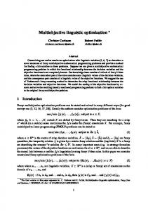
Therefore, in order to resolve those deficiencies, a general multi-objective model for location-allocation problems of MSW management system is developed in this paper. 3. Model development The multi-objective location-allocation model established in this section consists of two parts. In order to explicitly demonstrate the waste flow among different facilities in MSW management system, the conceptual flow chart is initially modeled and the mathematical model is then formulated. 3.1 Conceptual waste flow chart Different from previous single-stage or two-stage models, in this paper, the conceptual flow chart of MSW management system is modeled as a three-stage system in which direct shipment, transshipment, transportation and treatment of residue are taken into consideration. According to the functionality, facilities in MSW management system can be categorized into four levels. The first-level is waste collection point which is not only the end point of product life span but also the starting point of waste management. Waste collection service is usually provided by specialized waste management company or sanitation department of the government, and the waste collection points are always located next to the populated areas so as to deliver timely and efficient waste collection service to local residents. The second-level facility is transfer station which is the intermediate point between waste collection point and waste treatment facility. The introduction of transfer station can greatly enhance the integration of MSW management system and improve the transport efficiency, because it is much cheaper to transport a large amount of solid waste over long distance due to economy of scale. In transfer station, different types of waste are collected and distributed to corresponding facilities for further treatment. Besides, pre-processing of MSW including sorting, crushing and compression is also performed at some transfer stations in order to improve the processing efficiency and quality of downstream treatments within MSW management system. In this threestage MSW management system, waste handling facilities are classified into two types. The recycling facility and waste-to-energy (WTE) facility, i.e., incineration plant, composting plant, mechanical biological treatment (MBT), etc., at which residues may be generated in the waste recycling/treatment process, are defined as third-level facility. The fourth-level facility is disposal facility which is the final destination of both waste and residue. Normally, it is the sanitary landfill in MSW management system. Fig. 1 shows the waste flow through the entire MSW management system. As shown in this figure, the MSW is transported along one direction from the starting point (first-level facility) via intermediate point (second- and third-level facility) towards final destination (fourth-level facility). The MSW collected at each generation point can either be directly transported to third- and/or fourth-level facility for recycling/treatment/proper disposal, or be first transported to second-level facility for pre-processing and further distribution. In MSW management system, direct shipment and transshipment are usually combined to distribute different types of waste. Due to this reason, the three-stage conceptual waste flow chart has better adaptation for the general characteristics of MSW management system. In addition, from the logistics perspective, the reverse waste flow from downstream facilities to upstream facilities, which may increase the level of difficulty in model formulation and computation, can be effectively eliminated in this system.
Cite this article as: Yu, H. & Solvang, W.D. Environ Syst Decis (2017) 37: 289. https://doi.org/10.1007/s10669-017-9632-y
This copy is the accepted manuscript by Environment Systems and Decisions. The final version of the paper is available on Springerlink: https://link.springer.com/article/10.1007/s10669-017-9632-y
Fig.1 Conceptual framework of MSW management
Before the multi-objective location-allocation model for MSW management system is formulated, some assumptions have to be primarily defined as follows.
The related data of locations of each waste collection points and candidate points for new facilities, (planned) facility capacity, waste generation, unit waste treatment/transportation costs as well as the other necessary parameters are known or can be estimated in the studied area. Both heterogeneous and homogenous solid waste from one waste collection point can either be directly transported for treatment or be distributed through transshipment. The number of service (second-level) and treatment (third- and fourth-level) facilities that serve one waste collection point is unlimited, which means MSW from one collection point can be simultaneously allocated to several facilities for treatment or transshipment. The costs objective function is assumed to be linear function or segmented linear function in nature. The transportation costs of MSW are directly proportional to the transported waste quantity and distance, and the waste treatment costs are directly proportional to the processed waste amount. The time-varying parameters are not taken into consideration in this model. For example, the net present value (NPV) and discount factor are not formulated when facility depreciation costs are calculated. The model and decision making consider normal operation of MSW management system, so the additional costs associated with the equipment failure or malfunction of facilities are not taken into account.
3.2 Mathematical model The mathematical model formulated in this section aims to thoroughly describe the three-stage waste management system and to optimally manage the interactions among different objectives. There are three objective functions in this model, which are illustrated in Eq. (1), Eq. (2) and Eq. (3), respectively. The definitions of decision variables and parameters are first given as follows. Cite this article as: Yu, H. & Solvang, W.D. Environ Syst Decis (2017) 37: 289. https://doi.org/10.1007/s10669-017-9632-y
This copy is the accepted manuscript by Environment Systems and Decisions. The final version of the paper is available on Springerlink: https://link.springer.com/article/10.1007/s10669-017-9632-y
Parameters: I, i
Set and index of first-level point (waste generation and collection);
J, j
Set and index of the candidate point of second-level facilities;
K, k
Set and index of the candidate point of third-level facilities;
L, l
Set and index of the candidate point of fourth-level facilities;
H, h
Set and index of the communities or other type of important points affected by waste treatment;
cij, cik, cil, cjk, cjl, ckl
Unit waste transportation costs from i to j, from i to k, from i to l, from j to k, from j to l and from k to l;
F j , F k, F l
Fixed facility costs of facility j, k and l;
f j , f k, f l
Unit variable waste treatment costs of facility j, k and l;
bk
Unit profit generated from waste recycling or treatment at facility k;
Eij, Eik, Eil, Ejk, Ejl, Ekl
Emission coefficient of waste transportation from i to j, from i to k, from i to l, from j to k, from j to l and from k to l;
Lij, Lik, Lil, Ljk, Ljl, Lkl
Load capacity of transport vehicle from i to j, from i to k, from i to l, from j to k, from j to l and from k to l;
Sh
Size of affected community or relevant importance of other type of affected point;
R k, R l
level of environmental impact of waste treatment facility;
Xkh, Xlh
Pollution compensation coefficient to each affected point;
CAj, CAk, CAl
Capacity of facility j, k and l;
Limitj, Limitk, Limitl
Lower limits of facility j, k and l;
dhk, dhl
Euclidean matric between h and k, and between h and l;
α, δ, µ, θ
Adjustment parameters;
Dx
Depreciation costs of facility x;
Ccx
Construction costs of facility x including the interests of bank loan;
Lx
Expected life span of facility x;
Z
An infinite positive number;
Al
The waste amount treated at facility l;
Gi
The waste amount collected at facility i;
pj, pk, pl
Maximum number of each kind of facility to be built;
rj, rk
Input-Output rate at facility j and facility k;
Decision variables
Cite this article as: Yu, H. & Solvang, W.D. Environ Syst Decis (2017) 37: 289. https://doi.org/10.1007/s10669-017-9632-y
This copy is the accepted manuscript by Environment Systems and Decisions. The final version of the paper is available on Springerlink: https://link.springer.com/article/10.1007/s10669-017-9632-y xj, xk, xl
Boolean variable which decides whether the candidate point is selected for building waste treatment facility, if it equals to 1, the candidate point is chosen, if it equals to 0, otherwise;
wij, wik, wil, wjk, wjl, wkl
The waste amount transported from i to j, from i to k, from i to l, from j to k, from j to l and from k to l;
Minimize overall system costs: Min ∑ ∑ 𝑐𝑖𝑗 𝑤𝑖𝑗 + ∑ ∑ 𝑐𝑖𝑘 𝑤𝑖𝑘 + ∑ ∑ 𝑐𝑖𝑙 𝑤𝑖𝑙 + ∑ ∑ 𝑐𝑗𝑘 𝑤𝑗𝑘 + ∑ ∑ 𝑐𝑗𝑙 𝑤𝑗𝑙 𝑖∈𝐼 𝑗∈𝐽
𝑖∈𝐼 𝑘∈𝐾
𝑖∈𝐼 𝑙∈𝐿
𝑗∈𝐽 𝑘∈𝐾
𝑗∈𝐽 𝑙∈𝐿
+ ∑ ∑ 𝑐𝑘𝑙 𝑤𝑘𝑙 + ∑ 𝑥𝑗 (𝐹𝑗 + 𝑓𝑗 ∑ 𝑤𝑖𝑗 ) 𝑘∈𝐾 𝑙∈𝐿
𝑗∈𝐽
𝑖∈𝐼
(1)
+ ∑ 𝑥𝑘 (𝐹𝑘 + 𝑓𝑘 (∑ 𝑤𝑖𝑘 + ∑ 𝑤𝑗𝑘 )) 𝑘∈𝐾
𝑖∈𝐼
𝑗∈𝐽
+ ∑ 𝑥𝑙 (𝐹𝑙 + 𝑓𝑙 (∑ 𝑤𝑖𝑙 + ∑ 𝑤𝑗𝑙 + ∑ 𝑤𝑘𝑙 )) 𝑙∈𝐿
𝑖∈𝐼
𝑗∈𝐽
𝑘∈𝐾
Minimize GHG emissions: Min ∑ ∑ 𝑖∈𝐼 𝑗∈𝐽
𝐸𝑖𝑗 𝑤𝑖𝑗 𝐸𝑗𝑘 𝑤𝑗𝑘 𝐸𝑗𝑙 𝑤𝑗𝑙 𝐸𝑖𝑘 𝑤𝑖𝑘 𝐸𝑖𝑙 𝑤𝑖𝑙 +∑∑ + ∑∑ +∑∑ + ∑∑ 𝐿𝑖𝑗 𝐿𝑖𝑘 𝐿𝑖𝑙 𝐿𝑗𝑘 𝐿𝑗𝑙 𝑖∈𝐼 𝑘∈𝐾
𝑖∈𝐼 𝑙∈𝐿
𝑗∈𝐽 𝑘∈𝐾
𝑗∈𝐽 𝑙∈𝐿
𝐸𝑘𝑙 𝑤𝑘𝑙 +∑∑ 𝐿𝑘𝑙
(2)
𝑘∈𝐾 𝑙∈𝐿
Minimize Environmental impact: Min ∑(𝑆ℎ )𝛼 ∑ ℎ∈𝐻
𝑘∈𝐾
(𝑋𝑘ℎ 𝑅𝑘 )𝛿 (∑ 𝑤𝑖𝑘 + ∑ 𝑤𝑗𝑘 ) (𝑑𝑘ℎ )𝜃 𝑖∈𝐼
+ ∑(𝑆ℎ )𝛼 ∑ ℎ∈𝐻
𝑙∈𝐿
𝑗∈𝐽
(3)
)𝛿
(𝑋𝑙ℎ 𝑅𝑙 (∑ 𝑤𝑖𝑙 + ∑ 𝑤𝑗𝑙 + ∑ 𝑤𝑘𝑙 ) (𝑑𝑙ℎ )𝜃 𝑖∈𝐼
𝑗∈𝐽
𝑘∈𝐾
Eq. (1) is the cost-minimization objective function. The overall system costs are comprised of facility operating costs and waste transportation costs. Facility operating costs include the fixed annual costs and variable waste treatment costs. In MSW management, the first one usually refers to facility depreciation costs, maintenance costs, personnel costs as well as other fixed annual investments, while the other one mainly refers to the energy consumption costs, overtime costs and other variable costs that are directly proportional to the waste amount. Facility depreciation costs constitute a great share of fixed annual costs, and it is related to facility construction costs and expected life span. Eq. (4) is a simplified formula which can be applied in roughly calculating and estimating the depreciation costs. The facility depreciation costs Cite this article as: Yu, H. & Solvang, W.D. Environ Syst Decis (2017) 37: 289. https://doi.org/10.1007/s10669-017-9632-y
This copy is the accepted manuscript by Environment Systems and Decisions. The final version of the paper is available on Springerlink: https://link.springer.com/article/10.1007/s10669-017-9632-y are determined by the construction costs and bank interests over the entire payback period (overall investment for constructing the facility), and expected life span of the facility, and it is noted that the value change of currency within the facility life span caused by inflation or deflation is not taken into account in this equation. When the system design is performed on a multi-period basis, the different cost components in Eq. (1) should be discounted, as discussed in Zhang et al. (2011), and the facility depreciation costs should be considered and calculated as an equivalent annual costs. For more information and discussion for the facility cost estimation of MSW management, the research works conducted by Tsilemou and Panagiotakopoulos, (2006) and Komilis and Liogkas (2014) can be referred.
𝐷𝑥 =
𝐶𝑐𝑥 , 𝑥 ∈ {𝑗, 𝑘, 𝑙 } 𝐿𝑥
(4)
Excessive GHG emissions have become the most important driving force for global warming and climate change (Nojima et al., 2016), so the minimization of GHG emissions is of importance. Eq. (2) aims at minimizing the GHG emissions from the transportation of MSW. In this model, GHG emissions are directly proportional to the transported waste amount and the emission coefficient. The emission coefficient is mainly determined by the type transport distance, and it increases with the increase of transport distance. Furthermore, the emission coefficient is also affected by the type of transport vehicle, fuel consumption, technical level, terrain, and driving habits (Elhedhli and Merrick, 2012). In this equation, the GHG emissions are inversely proportional to the load capacity of transport vehicle, because, as a general rule, the number or frequency of transportation of MSW decreases accordingly with the increase of the load capacity of transport vehicles. Herein, it is noted that the facility-related GHG emissions are not formulated in this equation due to the fact that it may lead to inappropriate solutions in the design of MSW management system. For example, a large amount of MSW may be allocated to landfill but not incineration plant due to its more GHG emissions, however, this is not the proper solution for a sustainable MSW management system, because the environmental impact of landfill is much severer than incineration plant. Therefore, the facilityrelated GHG emissions are considered as one of the indicators of environmental impact of the waste treatment facility. Eq. (3) aims at minimizing the environmental impact of waste treatment facilities and it is derived from a disutility function. In Eq. (3), the environmental impact is directly related to the amount of MSW treated and the size (population) of influenced community or the relative importance of affected point, while it is inversely related to the Euclidean matric (straight-line distance) from waste treatment facility to affected point. Meanwhile, the waste treatment technology applied in each facility determines the level of environmental impact, which pushes the result of this objective function to more application and practices of environmentally friendly technologies. Some affected points may be more sensitive to and severely influenced by a certain type of waste treatment facility. For instance, the leak of high-density toxic leachate from landfill imposes much higher level of environmental impact to surface and ground water source than other types of affected points. The pollution compensation coefficient is therefore introduced to Eq. (3) for balancing the level of environmental impact of waste treatment facilities with respect to each affected point. Adjustment parameters 𝛼, 𝛿 and 𝜃 represent the corresponding importance of each impact factor, which increase the flexibility of this objective function. For example, if adjustment parameter 𝛼 is set to 0, the influence of community size is eliminated, but the equity or social fairness will be improved, which means a larger share of potential risks associated with waste treatment cannot be imposed to a community due to its small size or population. In addition, the environmental impact of waste collection points and transfer stations are not accounted in Eq. (3) due to their insignificant influences on the environment. When determining the value of adjustment parameters, stakeholders’ involvement is important due to the potential influence on the design and planning of MSW
Cite this article as: Yu, H. & Solvang, W.D. Environ Syst Decis (2017) 37: 289. https://doi.org/10.1007/s10669-017-9632-y
This copy is the accepted manuscript by Environment Systems and Decisions. The final version of the paper is available on Springerlink: https://link.springer.com/article/10.1007/s10669-017-9632-y management system. The influence of adjustment parameters (𝛼 = 1, 𝛿 = 1 and 𝜃 = 1) may be eliminated in decision-making when time or relevant information are in scarce. Besides the objective functions, six sets of constraints are also formulated in this model so that the mass balance requirements, national and regional environmental legislations, pre-assumptions, facility capacity and compatibility as well as other relevant requirements can be fulfilled. And they are presented as follows.
∑ 𝑤𝑖𝑗 + ∑ 𝑤𝑖𝑘 + ∑ 𝑤𝑖𝑙 = 𝐺𝑖 , ∀𝑖 ∈ 𝐼 𝑗∈𝐽
𝑘∈𝐾
(∑ 𝑤𝑖𝑗 ) 𝑟𝑗 = ∑ 𝑤𝑗𝑘 + ∑ 𝑤𝑗𝑙 , ∀𝑗 ∈ 𝐽 𝑖∈𝐼
𝑘∈𝐾
𝑗∈𝐽
𝑗∈𝐽
(7)
𝑙∈𝐿
∑ 𝑤𝑖𝑙 + ∑ 𝑤𝑗𝑙 + ∑ 𝑤𝑘𝑙 = 𝐴𝐿 , ∀𝑙 ∈ 𝐿 𝑖∈𝐼
(6)
𝑙∈𝐿
(∑ 𝑤𝑖𝑘 + ∑ 𝑤𝑗𝑘 ) 𝑟𝑘 = ∑ 𝑤𝑘𝑙 , ∀𝑘 ∈ 𝐾 𝑖∈𝐼
(5)
𝑙∈𝐿
(8)
𝑘∈𝐾
The first group of equations is mass balance constraint. Eq. (5) restricts the MSW collected at each demand point can be totally served and transported to downstream facilities for further treatment. Eq. (6) depicts the relationship between input and output waste amount at second-level facilities, and rj is less than 1 when preprocessing of MSW is performed at transfer station. Eq. (7) illustrates the output waste amount equals to the product of input waste amount and waste-to-residue rate at third-level facilities. Eq. (8) guarantees the residue generated in waste treatment process and the wastes cannot be treated at third-level facilities are totally disposed at four-level facilities. Mass balance constraint is the basic logistical requirement and is of significant importance due to its necessity to the computation of this model, and the weight loss at transfer stations is emphasized to better represent the characteristics of MSW management system.
𝐿𝑖𝑚𝑖𝑡𝑗 𝑥𝑗 ≤ ∑ 𝑤𝑖𝑗 ≤ 𝐶𝐴𝑗 𝑥𝑗 , ∀𝑗 ∈ 𝐽
(9)
𝑖∈𝐼
𝐿𝑖𝑚𝑖𝑡𝑘 𝑥𝑘 ≤ (∑ 𝑤𝑖𝑘 + ∑ 𝑤𝑗𝑘 ) ≤ 𝐶𝐴𝑘 𝑥𝑘 , ∀𝑘 ∈ 𝐾 𝑖∈𝐼
(10)
𝑗∈𝐽
𝐿𝑖𝑚𝑖𝑡𝑙 𝑥𝑙 ≤ 𝐴𝑙 ≤ 𝐶𝐴𝑙 𝑥𝑙 , ∀𝑙 ∈ 𝐿
(11)
The second group of formulas is facility capacity constraint. Eqs. (9), (10) and (11) restrict the waste amounts treated at facility j, k and l are less than their capacity or planned capacity, and more than their lower limits. Herein, the lower limits are introduced into capacity constraint in order to maintain the utilization of facilities at an acceptable level. 𝑤𝑖𝑗 ≤ 𝑥𝑗 𝑍, ∀𝑖 ∈ 𝐼, 𝑗 ∈ 𝐽
(12)
Cite this article as: Yu, H. & Solvang, W.D. Environ Syst Decis (2017) 37: 289. https://doi.org/10.1007/s10669-017-9632-y
This copy is the accepted manuscript by Environment Systems and Decisions. The final version of the paper is available on Springerlink: https://link.springer.com/article/10.1007/s10669-017-9632-y 𝑤𝑖𝑘 ≤ 𝑥𝑘 𝑍, ∀𝑖 ∈ 𝐼, 𝑘 ∈ 𝐾
(13)
𝑤𝑖𝑙 ≤ 𝑥𝑙 𝑍, ∀𝑖 ∈ 𝐼, 𝑙 ∈ 𝐿
(14)
𝑤𝑗𝑘 ≤ 𝑥𝑗 𝑥𝑘 𝑍, ∀𝑗 ∈ 𝐽, 𝑘 ∈ 𝐾
(16)
𝑤𝑗𝑙 ≤ 𝑥𝑗 𝑥𝑙 𝑍, ∀𝑗 ∈ 𝐽, 𝑙 ∈ 𝐿
(17)
𝑤𝑘𝑙 ≤ 𝑥𝑘 𝑥𝑙 𝑍, ∀𝑘 ∈ 𝐾, 𝑙 ∈ 𝐿
(18)
The third group of constraints restricts the transportation between two nodes within MSW management system can happen only when the respective candidate locations are selected. For example, Eq. (12) restricts the waste can be transported to and treated at second-level facility j only when the candidate point j is selected for opening transfer station. Likewise, Eqs. (13)-(18) are transportation constraints for third-level and fourth-level facility.
∑ 𝑥𝑗 ≤ 𝑝𝑗 , ∀𝑗 ∈ 𝐽
(19)
𝑗∈𝐽
∑ 𝑥𝑘 ≤ 𝑝𝑘 , ∀𝑘 ∈ 𝐾
(20)
𝑘∈𝐾
∑ 𝑥𝑙 ≤ 𝑝𝑙 , ∀𝑙 ∈ 𝐿
(21)
𝑙∈𝐿
Eqs. (19), (20) and (21) restrict the maximum number of second-level, third-level and fourth-level facility to be opened in MSW management system, respectively. 𝑥𝑗 ∈ {0,1}, 𝑥𝑘 ∈ {0,1}, 𝑥𝑙 ∈ {0,1}, 𝑖 ∈ 𝐼, 𝑗 ∈ 𝐽, 𝑙 ∈ 𝐿
(22)
𝑤𝑖𝑗 ≥ 0, 𝑤𝑖𝑘 ≥ 0, 𝑤𝑖𝑙 ≥ 0, 𝑤𝑗𝑘 ≥ 0, 𝑤𝑗𝑙 ≥ 0, 𝑤𝑘𝑙 ≥ 0, 𝑖 ∈ 𝐼, 𝑗 ∈ 𝐽, 𝑘 ∈ 𝐾, 𝑙 ∈ 𝐿
(23)
The last group of constraints is the basic requirements for decision variables. Eq. (22) determines if the candidate point is selected for opening the respective facility. Eq. (23) guarantees the waste amount transported from/to each facility is a positive number.
Min {(∑ 𝑤𝑖𝑘 + ∑ 𝑤𝑖𝑙 ) , ∑ 𝑤𝑖𝑗 } , 𝑖 ∈ 𝐼 𝑘∈𝐾
𝑙∈𝐿
(24)
𝑗∈𝐽
In addition, as a general model for the design of MSW management system, some prerequisites and constraints can be relaxed or tightened for adapting the characteristic of a specific MSW management system. For instance, if the direct shipment and transshipment of solid waste from one collection point cannot be performed simultaneously and only one transportation mode can be applied in each waste collection point, Eq. (24) can be applied in order to select the proper transportation mode for each waste collection point. Cite this article as: Yu, H. & Solvang, W.D. Environ Syst Decis (2017) 37: 289. https://doi.org/10.1007/s10669-017-9632-y
This copy is the accepted manuscript by Environment Systems and Decisions. The final version of the paper is available on Springerlink: https://link.springer.com/article/10.1007/s10669-017-9632-y
3.3 Model solution In the design and planning of MSW management system, qualitative analysis and quantitative calculations are usually combined in order to generate an appropriate solution. For resolving this multi-objective location-allocation model, the qualitative analysis should first be applied in narrowing the set of feasible solutions. Due to the significant environmental impact of some waste treatment facilities, it is necessary to select qualified candidate locations that minimize the risks of pollution and negative influence on the health and lifestyle of nearby residents. In most countries, a buffer area for waste treatment facility as well as other undesirable facilities is imposed in order to decrease the potential risks. In addition, similar with the function of adjustment parameter 𝛼, the buffer area requirement can also be used for increasing the social fairness and equity. In this model, although the inequity-minimization objective is not formulated independently, the inequity can still be maintained in an acceptable range through adjusting those two parameters. After the preliminary selection of candidate locations, quantitative calculation will be performed for providing decision-makers with analytical scenario-based results. In this model, the objective functions cannot be combined directly in a quasi-addictive form (i.e., distributing weights to each of them), because their formulas have different measures of units. The units of Eq. (1) is a kind of currency while Eqs. (2) and (3) are index and unitless. Therefore, a normalization function from Nema and Gupta (1999) is employed in order to composite those three objective functions (Eq. (25)). Practices with similar methods for combining multiple objectives with different measures of units are also provided in Sheu (2007), Sheu and Lin (2012), Yu et al. (2014) and Yu et al. (2015). 𝐶𝑜𝑠𝑡 𝑜𝑏𝑗𝑒𝑐𝑡𝑖𝑣𝑒 𝐺𝐻𝐺 𝑜𝑏𝑗𝑒𝑐𝑡𝑖𝑣𝑒 ) + 𝑊𝑡𝐺𝐻𝐺 ( ) Min 𝑊𝑡𝑐𝑜𝑠𝑡 ( 𝑂𝑝𝑡𝑖𝑚𝑎𝑙 𝑐𝑜𝑠𝑡 𝑂𝑝𝑡𝑖𝑚𝑎𝑙 𝐺𝐻𝐺 𝐸𝑛𝑣𝑖𝑟𝑜𝑛𝑚𝑒𝑛𝑡 𝑜𝑏𝑗𝑒𝑐𝑡𝑖𝑣𝑒 ) + 𝑊𝑡𝑒𝑛𝑣𝑖𝑟𝑜𝑛𝑚𝑒𝑛𝑡 ( 𝑂𝑝𝑡𝑖𝑚𝑎𝑙 𝐸𝑛𝑣𝑖𝑟𝑜𝑛𝑚𝑒𝑛𝑡
(25)
Herein, 𝑊𝑡𝑐𝑜𝑠𝑡 , 𝑊𝑡𝐺𝐻𝐺 and 𝑊𝑡𝑒𝑛𝑣𝑖𝑜𝑟𝑛𝑚𝑒𝑛𝑡 are the weight of each utility function, and 𝑂𝑝𝑡𝑖𝑚𝑎𝑙 𝑐𝑜𝑠𝑡, 𝑂𝑝𝑡𝑖𝑚𝑎𝑙 𝐺𝐻𝐺 and 𝑂𝑝𝑡𝑖𝑚𝑎𝑙 𝐸𝑛𝑣𝑖𝑟𝑜𝑛𝑚𝑒𝑛𝑡 represent the individual optimal value of each objective function, respectively. Eq. (25) aims at eliminating the units in the objective functions and optimizing the overall system performance with respect to the given weight combination. The individual optimal system operating costs, GHG emissions and environmental impact can be calculated by separately solving each single objective function. The cost utility, GHG emissions utility and environmental impact utility can then be calculated through using Eqs. (1), (2) and (3) divided by their respective individual optimal value, so each utility function should be more than or equal to 1 (best-case scenario). Similar with the meaning of standard deviation in quality management, which represents the level of deviation of tested products to the standard size and determines if the quality of this batch of products is satisfied with the requirement, the utility of each objective function in Eq.(25) illustrates the level of deviation from the individual optimal value. Therefore, the less the utility of each objective function achieves, the better the result is (low level of deviation from the individual optimal value). The overall system performance can then be obtained through multiplying by the respective weights of costs, GHG emissions and environmental impact, and the optimal solution to this composite objective function is the one with the smallest utility. In addition, the summation of the weights is specified in this model, and it equals to 1. Therefore, the optimal achievable overall utility is 1 when the utility of each objective function equals to 1, but in practice, it is impossible to be achieved and the value of the overall utility of this composite model should always be more than 1.
4. Numerical experiment Cite this article as: Yu, H. & Solvang, W.D. Environ Syst Decis (2017) 37: 289. https://doi.org/10.1007/s10669-017-9632-y
This copy is the accepted manuscript by Environment Systems and Decisions. The final version of the paper is available on Springerlink: https://link.springer.com/article/10.1007/s10669-017-9632-y An example is given in this section to illustrate the application of proposed model. The parameters are defined as a very small set representing a real-world decision-making for the network configuration of MSW management system. The purpose of this example is to determine the optimal configuration of a regional MSW management system with six communities (i1,i2,i3,i4,i5,i6), five candidate points for transfer stations (j1,j2,j3,j4,j5), four candidate points for incineration plants and composting plants (k1,k2,k3,k4,k5), and four candidate points for landfills (l1,l2,l3,l4). In this example, the set of waste generation points equals to the set of affected communities (i=h). The maximum number of transfer stations, incineration plants and composting plants, and landfills to be opened are pj=2, pk=2 and pl=1, respectively. In order to have a better representation of generality, the input parameters are generated randomly, and the units of parameters are not specified. Table 2 presents the parameter intervals used for generating random numerical values. As shown in the table, the population of communities is between 10000 and 50000, and the waste generation of each community is directly related to the population and waste generation per capita. In this example, a reasonable assumption is applied for depicting the proportionality of both unit transportation costs and GHG emission factors with transport distance. And the different intervals for multiplying the distance in unit transportation costs and GHG emissions represents the different types of transport vehicles used in each itinerary. Besides, it is also noted that the ratio between Emission coefficient and location capacity in Eq. (2) is linearized for simplifying the problem. And intervals for other parameters are also given in the table. In addition, adjustment parameters 𝛼, 𝛿 and 𝜃 are set to 1, 2 and 0.8 for calculating the environmental impact, and the weight of individual cost objective, individual GHG emission objective and individual environmental impact objective are given as 0.4, 0.3 and 0.3 for determining the optimal value of the overall performance. The proposed model is resolved by using Lingo 11.0 optimization solver on a personal computer with Inter Core2 Quad 2.4 GHz CPU and 2 GB RAM under windows 7 operating system. The CPU running time for calculating the optimal value of individual cost objective, individual GHG emission objective, individual environmental impact objective and overall performance objective are 6 seconds, 9 seconds, 10 seconds and 4 seconds, respectively. The computational results are presented in Tables 3 and 4 and Figs. 2 and 3. Table 3 illustrates the total system costs, GHG emissions, environmental impact and selection of facilities of individual optimal cost scenario, individual optimal GHG emissions scenario, individual optimal environmental impact scenario as well as the optimal overall performance scenario, and Table 4 presents the transportation strategy of MSW in each scenario. Fig. 2 shows the comparison of system operating costs, GHG emissions and environmental impact of each scenario, and the value of system operating costs, GHG emissions and environmental impact are normalized through dividing by 103, 103 and 106, respectively, so that the comparison is presented in an intuitive fashion. The comparison of the cost components is given in Fig. 3, and the value of each cost component is normalized as well. Table 2 Parameter intervals used for generating random numerical values
Parameter
Interval
Population
Pi (Sh)
(10000, 50000)
Waste generation
Gi
(200, 300)*Pi
Fixed costs
Fj, Fk, Fl
(200, 300) *105, (400, 500)* 105, (250, 400)* 105
Variable costs
fj, fk, fl
(5, 10), (5, 20), (5, 15)
Capacity
CAj, CAk, CAl
(300, 400) *105, (200, 300)* 105, (200, 400)* 105
Lower limits
Limitj, Limitk, Limitl
(40, 80) *105, (50, 80)* 105, (30, 50)* 105
Input-output rate
rj, rk
(0.7, 1), (0.4, 0.7)
Distance
dsij dsik dsil dsjk dsjl dskl
(5, 10), (20, 40), (30, 50), (15, 25), (15, 30), (10, 30)
Cite this article as: Yu, H. & Solvang, W.D. Environ Syst Decis (2017) 37: 289. https://doi.org/10.1007/s10669-017-9632-y
This copy is the accepted manuscript by Environment Systems and Decisions. The final version of the paper is available on Springerlink: https://link.springer.com/article/10.1007/s10669-017-9632-y Unit transportation costs
cij, cik, cil, cjk, cjl, ckl
(3, 6)*dsij, (4, 7)*dsik, (4, 7)*dsil, (2, 5)*dsjk, (2, 5)*dsjl, (3, 5)*dskl
Emission coefficient/Load
E/Lij, E/Lik, E/Lil, E/Ljk, E/Ljl, E/Lkl
(2, 5)*dsij, (2, 5)*dsik, (2, 5)*dsil, (4, 8)*dsjk, (4, 8)*dsjl, (2, 5)*dskl
Environmental impact level
Rk, Rl
(1, 3), (2, 5)
Euclidean matric
dhk,(dik) dhl dil)
dsik/1.5, dsil/1.5
Table 3 Optimal value and selection of facilities of individual cost objective, individual GHG emission objective, individual environmental impact objective as well as the overall performance objective
Scenario
Value of objective functions 3
Cost (10 ) Optimal cost Optimal GHG emission Optimal environmental impact Optimal overall performance
Facility selection
3410356 6278061 7081819
GHG emissions (103) 4916766 3447465 7090780
Environmental impact (106) 5293771 6095225 3173146
j1, j3, l3 j2, j3, k1, k2, l3 j1, j2, k1, l2
4794319
3851658
3809423
j1, j5, l1
As shown in the tables and figures, candidate points j1, j3 and l3 are selected for opening transfer stations and landfill when the overall system operating costs are minimized. It is noted that the least numbers of facilities are opened in this scenario in order to minimize the overall system costs, and both facility costs and transportation costs are significantly reduced compared with the other scenarios. In this scenario, the lower fixed costs and unit processing costs accompanying with higher input-output rate at locations j1 and j3 become advantage for reducing the second-level facility costs. Compared with landfill, the higher fixed investment and additional costs for the transportation of residues become the main obstacles for opening third-level facilities even though they are more environmentally friendly. In addition, all the MSW are distributed via transfer stations, and no direct shipment between waste generation points and landfill exists. And this has revealed that transportation of MSW via transfer stations has better economic efficiency than direct shipment. When the optimal value of individual GHG emissions objective is obtained, candidate points j2, j3, k1, k3 and l3 are chosen. Compared with the individual optimal cost scenario, the overall system operating costs and environmental impact increase by 84.1% and 15.1%, respectively, and the GHG emissions reduce by 29.9%. It is noted that the maximum numbers of all levels of facilities are reached in this scenario, and the network configuration is the most complex one. The individual GHG emissions objective aims at minimizing the GHG emissions from the transportation of MSW, so the transportation network of MSW management system is planned in a more complex manner in order to enhance the network integration and reduce the overall GHG emissions. Furthermore, as shown in Table 4 and Fig. 3, the increase of system operating costs is mainly contributed by the significant increase in the transportation costs in this scenario, and this is caused by two reasons. First, the numbers of itinerary in MSW transportation are more than that in the other scenarios due to the complex network configuration. Second, in this scenario, more advanced transport vehicles with less GHG emissions are applied in the transportation of waste and residue in order to reduce the overall GHG emissions of MSW management system, and this will lead to more investments in the upgrade of transport vehicles (Wang et al., 2011).
Cite this article as: Yu, H. & Solvang, W.D. Environ Syst Decis (2017) 37: 289. https://doi.org/10.1007/s10669-017-9632-y
This copy is the accepted manuscript by Environment Systems and Decisions. The final version of the paper is available on Springerlink: https://link.springer.com/article/10.1007/s10669-017-9632-y
Fig.2 Comparison of system operating costs, GHG emissions and environmental impact of each scenario
Fig.3 Comparison of total costs, facility costs and transportation costs of each scenario
Candidate points j1, j2, k1 and l2 are selected when the optimal value of individual environmental impact objective is achieved. Compared with the individual optimal cost scenario, the system operating costs and GHG emissions increase by 107.6% and 44.2%, and the environmental impact decrease by 40%. Compared with the individual optimal GHG emissions scenario, the system operating costs and GHG emissions increase by 12.8% and 105.7%, and the environmental impact decrease by 47.9%. The environmental impact is determined by the waste amount processed and the technology used at the third-level and fourth-level facilities. In this scenario, it is observed that all the MSW are first compressed at and then distributed via transfer stations, because this will significantly reduce the weight of MSW treated at the incineration plant and landfill due to the elimination of the moisture content. Candidate points j1 and j2 are chosen in this scenario, because of their higher input-output rate. Compared with the individual optimal cost scenario, more solid wastes are treated at composting plants or incineration plant in this scenario in order to minimize the environmental impact of the MSW management system, and both facility costs and transportation costs are dramatically increased. In general, when the minimization of environmental impact is the primary target in the decision-making, both the second-level and third-level facilities become preferable due to the loss of weight and improved environmental sustainability, and the amount of waste directly sent to landfill is greatly Cite this article as: Yu, H. & Solvang, W.D. Environ Syst Decis (2017) 37: 289. https://doi.org/10.1007/s10669-017-9632-y
This copy is the accepted manuscript by Environment Systems and Decisions. The final version of the paper is available on Springerlink: https://link.springer.com/article/10.1007/s10669-017-9632-y reduced. This results in more investments of MSW management due to the fact that more facilities have to be opened at the second-level and third-level, and in this scenario, the waste is transported in a more complex network leading to an increased transportation costs of MSW. Furthermore, without the consideration of the use of advanced transport vehicles with less GHG emissions, this complex transportation network also results in a significant increase in the overall GHG emissions of MSW management system.
Table 4 Transportation strategy of MSW in each scenario (Normalized by dividing 103)
Itinerary
wij
Objective Individual costs
Individual GHG emissions
Individual impacts
Overall performance
(1, 3)/9838158
(2, 2)/6330580
(1, 1)/3247331
(1, 5)/9838158
(2, 3)/6330580
(4, 3)/2280321
(1, 2)/6590827
(2, 1)/2150738
(3, 1)/9604515
(5, 2)/7427048
(2, 1)/6330580
(2, 5)/115031
(4, 1)/7219696
(6, 3)/3499008
(3, 1)/9604515
(3, 5)/9604515
(5, 3)/7427048
(4, 1)/7219696
(4, 5)/7219696
(6, 3)/3499008
(5, 1)/7427048
(5, 5)/7427048
(6, 2)/3499008
(6, 1)/3499008
wik
(1, 3)/9838158 (3, 1)/9604515 (4, 1)/4939375
wil
(2, 1)/4064811
wjk
wjl
wkl
(1, 1)/12432800
(1, 3)/13459370
(2, 3)/13757630
(1, 2)/14630540
(1, 1)/4519797
(3,3)/24385310
(3, 3)/5201396
(2, 2)/10089840
(5, 1)/27363560
(1, 3)/7271945
(1, 2)/6216399
(3, 3)/4919079
When the optimal value of the overall performance objective is reached, candidate locations j1, j5 and l1 are selected for opening the transfer stations and landfill. Compared with the optimal values of each individual objective function, the system operating costs, GHG emissions and environmental impact increase by 40.6%, 11.7% and 20%, respectively. In this scenario, most MSW are distributed via transfer stations and the only exception is the waste flow from community i2 from which 4064811 wastes are directly transported to landfill l1. It is clearly shown that the three individual objective functions are compromised with each other in the overall performance objective so as to obtain the optimal trade-off (minimum utility) with respect to the given combination of weights. Besides, it is also observed that, with the increased investment at 40.6% in the optimal overall performance scenario, the GHG emissions and environmental impact improve by 21.7% and 27%, respectively, compared with the individual optimal cost scenario. This Cite this article as: Yu, H. & Solvang, W.D. Environ Syst Decis (2017) 37: 289. https://doi.org/10.1007/s10669-017-9632-y
This copy is the accepted manuscript by Environment Systems and Decisions. The final version of the paper is available on Springerlink: https://link.springer.com/article/10.1007/s10669-017-9632-y reveals, with the evenly allocated weights to the GHG emissions objective and environmental impact objective in this numerical experiment, the increased amount of investment leads to more effective reduction of environmental impact of MSW management system.
Table 5 Sensitivity analysis
Scenario 1 2 3 4 5 6 7 8 9 10 11 12 13 14 15 16
Weight Wt1
Wt2
Wt3
0.5 0.25 0.25 0.6 0.1 0.3 0.8 0.1 0.1 0.4 0.2 0.4 1/3 0.7 0.2 0.1
0.25 0.5 0.25 0.3 0.6 0.1 0.1 0.8 0.1 0.4 0.4 0.2 1/3 0.2 0.1 0.7
0.25 0.25 0.5 0.1 0.3 0.6 0.1 0.1 0.8 0.2 0.4 0.4 1/3 0.1 0.7 0.2
Overall utility
Facility selection
1.2705 1.2513 1.2204 1.2193 1.1774 1.1646 1.1094 1.1268 1.1093 1.2484 1.205 1.2393 1.2738 1.1519 1.1373 1.2428
j1, j3, l3 j1, j5, k1, l1 j2, j5, k2, l2 j3, j5, l3 j2, j5, k4, l2 j2, j5, k2, l2 j1, j3, l3 j1, j5, k4, l1 j2, j5, k2, l2 j1, j5, l1 j1, j5, l1 j2, j5, k2, l2 j2, j5, k2, k4, l2 j1, j3, l3 j2, j5, k2, l2 j2, j3, k3, l3
In this section, sensitivity analysis with different combinations of the weight of each individual objective function is also performed, and the CPU running time for calculating the optimal result of each scenario varies between 3 and 9 seconds. The purpose of the sensitivity analysis is to present a series of Pareto solutions with respect to different combinations of weights. In the design of MSW management system, it could be extremely difficult for the decision maker to determine the weight of each objective function at the initial stage, and the result from the sensitivity analysis provides decision makers with a very good reference of the trade-offs among different objectives with the change of weights. The combination of weights used in the sensitivity analysis is adopted from Samanlioglu (2013) in order to generate dispersed representations of Pareto solutions, and a detailed introduction for generating dispersed weight vectors is given by Steuer (1986). For generating the Pareto solutions, we resolve the problem for 16 times. Table 5 presents the result of the sensitivity analysis. It is clearly shown that the overall utility and network configuration vary significantly with the change of the weight combinations. The smallest overall utility 1.1094 is obtained in scenario 9 (0.1, 0.1 and 0.8) when facilities j1, j3, l3 are selected, and the largest overall utility1.2738 is achieved in scenario 13 when facilities j2, j5, k2, k4, l2 are chosen. The overall utility is an indicator revealing the sum of weighted deviations from the individual optimal performance, but the comparison is not meaningful
Cite this article as: Yu, H. & Solvang, W.D. Environ Syst Decis (2017) 37: 289. https://doi.org/10.1007/s10669-017-9632-y
This copy is the accepted manuscript by Environment Systems and Decisions. The final version of the paper is available on Springerlink: https://link.springer.com/article/10.1007/s10669-017-9632-y without the discussion of managerial insights. Due to this reason, we also compare the system operating costs, GHG emissions and environmental impact of each Pareto solution.
Table 6 Comparison of the Pareto solutions
Scenario
Cost (106)
Dev.C
Dev.G
Environmental impact (109)
Dev.E
1.8% 44.4% 35% 5.1% 67.7% 30.9% 0% 56.9% 35% 41.7% 41.7% 30.9% 48.6% 1.8% 30.9% 37.6% 0% 84%
GHG emissions (106) 4644 4015 5038 4813 3926 5200 4917 3616 5038 3804 3804 5200 4345 4644 5200 3581 4917 3447
1 2 3 4 5 6 7 8 9 10 11 12 13 14 15 16 Optimal cost Optimal GHG emission Optimal environmental impact
3472 4925 4062 3584 5718 4464 3410 5352 4602 4833 4833 4464 5066 3472 4464 4692 3410 6278
34.7% 16.5% 46.2% 36.6% 13.9% 50.8% 42.6% 4.9% 46.2% 10.4% 10.4% 50.9% 26% 34.7% 50.8% 3.9% 42.6% 0%
5390 3908 3285 5390 3452 3285 5294 4154 3285 3809 3809 3285 3424 5390 3285 5998 5294 6095
69.9% 23.1% 3.5% 69.9% 8.8% 3.5% 66.8% 30.9% 3.5% 20% 20% 3.5% 7.9% 69.9% 3.5% 89% 66.8% 92%
7082
107.6%
7091
105.7%
3173
0%
a Dev.C=Deviation
from the individual optimal costs, Dev.G=Deviation from the individual optimal GHG emission, Dev.E=Deviation from the individual optimal environmental impact
Table 6 shows the comparison of system operating costs, GHG emissions and environmental impact of each Pareto solution, and the deviation from the individual optimal performance is also illustrated in this table. Besides, three benchmarking scenarios (individual optimal costs, individual optimal GHG emissions and individual environmental impact) are included in the table. The combination of weights and deviation from the individual optimal value are also given in Fig. 4 and Fig. 5, respectively. With the result of the sensitivity analysis, decision makers do not have to make a rush decision on the allocation of weights to each objectives, and it enables the comparison of different scenarios. For example, when Wt1=0.8, Wt2=0.1 and Wt3=0.1 (Scenario 7), the optimal result is the same as the individual optimal cost objective. And then scenarios 10 and 12 are selected to compare with the trade-offs among costs, GHG emissions and environmental impact with respect to different weight combinations. Compared with Scenario 7, the overall system costs increase by 41.7%, and the GHG emissions and environmental impact decrease by 22.6% and 28% in scenario 10 (0.4, 0.4, 0.2). In scenario 12 (0.4, 0.2, 0.4), the total system costs and GHG emissions increase by 30.9% and 5.8%, respectively, and the environmental impact decreases by 37.9%. It is clear that scenario 12 is the better choice when the primary target of the design of MSW management system is to reduce the Cite this article as: Yu, H. & Solvang, W.D. Environ Syst Decis (2017) 37: 289. https://doi.org/10.1007/s10669-017-9632-y
This copy is the accepted manuscript by Environment Systems and Decisions. The final version of the paper is available on Springerlink: https://link.springer.com/article/10.1007/s10669-017-9632-y environmental impact in a cost-efficient manner, however, when the simultaneous balance of GHG emissions and environmental impact is focused, scenario 10 has a better performance with more cost increase.
Fig.4 Comparison of the weight combinations of the test scenarios
Fig.5 Comparison of the deviation from the individual optimal values of the test scenarios
In general, more costs have to be invested in order to reduce the GHG emissions and environmental impact of MSW management system, and the sensitivity of GHG emissions and environmental impact with increased investments (or cost efficiency) may vary greatly. The set of Pareto solutions provides decision makers with several different efficient options, and in reality, the one reflecting the preference of the decision makers will be selected to implement. 5. Computational efficiency In this section, numerical experiment of six scenarios with different size of problem is given in order to test the computational performance of the proposed model for resolving small, medium and large scale problems. The same data structure and parameter intervals from previous section are employed so that the computational efficiency of the proposed model is validated with a high level of confidence. In order to simplify the problem and avoid infeasible solutions, the model is relaxed to a uncapacitated formulation through taking out the constraints of the maximum number of each level of facilities to be opened (Eqs.(19)Cite this article as: Yu, H. & Solvang, W.D. Environ Syst Decis (2017) 37: 289. https://doi.org/10.1007/s10669-017-9632-y
This copy is the accepted manuscript by Environment Systems and Decisions. The final version of the paper is available on Springerlink: https://link.springer.com/article/10.1007/s10669-017-9632-y (21)). Table 7 presents the size of problem in each scenario in terms of the number of integer variables and the number of total variables for each objective function. As shown in the table, the number of integer variables increases incrementally by 15 from scenario 1 to 6, however, the number of total variables increases more dramatically, for instance, the number of total variables of individual cost objective increases from 180 at scenario 1 to 5580 at scenario 6. Based upon the size of problem, we divided the six scenarios into three groups: small scale (scenario 1 and 2), medium scale (scenario 3 and 4), and large scale (scenario 5 and 6). Table 7 Size of problem of each scenario
Scenario
Parameters
Integer variables
i
j
k
l
1
5
5
5
5
2
10
10
10
3
15
15
4
20
5 6
Total variables CtO
GgO
EtO
OrO
15
180
165
180
180
10
30
690
630
690
690
15
15
45
1440
1395
1440
1440
20
20
20
60
2520
2460
2520
2520
25
25
25
25
75
3900
3825
3900
3900
30
30
30
30
90
5580
5490
5580
5580
a CtO=individual
cost objective, GgO=individual GHG emission objective, EtO=individual environmental impact objective, OrO=overall utility objective
The computational results are illustrated in Table 8 and Fig. 6. As shown in Table 8, it is obviously that the time consumption for calculating the optimal value of each individual objective and overall utility objective increases gradually with the increase of the size of problem, and only one exception is observed in scenario 4 for calculating the minimum value of individual environmental impact, which requires more CPU running time than other scenarios. The individual cost objective is the most time consuming part, which requires much more time than other objective functions for calculating the global optimal value. Furthermore, it is also noted that the CPU running time for determining the optimal network configuration of individual environmental impact objective is around 300 seconds for both medium and large sized problems. In addition, all the six test scenarios in this section can be resolved with Lingo optimization solver within reasonable time. In general, small and medium sized problems can be resolved within ten minutes, but much more CPU running time is required for calculating the optimal result of large scale problems. Table 8 CPU times and optimal value of overall performance
Scenario
CPU times (seconds)
Optimal overall performance
CtO
GgO
EtO
OrO
1
20
1
1
8
1.1678
2
56
5
22
37
1.1529
3
246
79
323
232
1.1204
4
292
289
215
321
1.1061
5
1110
306
305
522
1.1186
6
1336
396
307
548
1.1336
Cite this article as: Yu, H. & Solvang, W.D. Environ Syst Decis (2017) 37: 289. https://doi.org/10.1007/s10669-017-9632-y
This copy is the accepted manuscript by Environment Systems and Decisions. The final version of the paper is available on Springerlink: https://link.springer.com/article/10.1007/s10669-017-9632-y
Fig.6 Comparison of system operating costs, GHG emissions, environmental impact and overall utility in different scenarios
Fig. 6 presents the comparison of the optimal value of individual cost objective, individual GHG emissions objective, individual environmental impact objective and overall performance objective in each scenario. As shown in the figure, system operating costs, GHG emissions and environmental impact of MSW management system increase gradually with the increase of waste generation and number of communities it serves, and this is because more facilities and transportations are required for dealing with the increased amount of solid wastes and satisfying the demands for MSW treatment from increased number of communities. Besides, it is also noted the increase system operating costs and GHG emissions over the six scenarios is approximately a linear function, however, the environmental impact has a sharper curve and a great increase from scenario 4 is observed, which means the increase of the size of MSW management system will bring more significant environmental impact on the nearby communities. In addition, as shown in the figure, the optimal value of overall utility is not proportional to the size of problem, which means no matter how large the problem is, the optimal overall balance of system operating costs, GHG emissions and environmental impact with constant weights belongs to a certain range. For the six test scenarios, the mean value and standard deviation of the optimal values of overall utility are 1.1332 and 0.0232, respectively.
6. Comparison of the case studies in previous research works In this section, the adaptability of the proposed generic multi-objective location-allocation model in the design of MSW management system is discussed through the comparison with the numerical experiments and case studies in previous research works. Section 4 illustrates the application of the model through a fullscale numerical experiment, however in reality, the location-allocation problem of MSW management may be in a smaller scale (e.g., only including one level or two levels of facilities). And sometimes, not all the objectives and constraints have to be taken into consideration due to the characteristics of the system, limitation of time and resources, or even the necessity to account. Therefore, the numerical experiments and case studies from some of the previous research works in Table 1 are selected to compare with the proposed model. Cite this article as: Yu, H. & Solvang, W.D. Environ Syst Decis (2017) 37: 289. https://doi.org/10.1007/s10669-017-9632-y
This copy is the accepted manuscript by Environment Systems and Decisions. The final version of the paper is available on Springerlink: https://link.springer.com/article/10.1007/s10669-017-9632-y The selected research works mainly focus on the design of MSW management system with certain input parameters, so the cases regarding hazardous waste management and time-varying parameters are not taken into account in this section. Table 9 presents the comparison and discussion of the adaptability of the proposed model to resolve the numerical experiments and case studies in previous research works. As shown in the table, all the numerical experiments and case studies from the previous studies with the similar setting of the problem structure can be resolved with the modification of the generic multi-objective locationallocation model. For most case studies, the generic model is simplified in order to adapt the characteristics of the problems with less objectives and/or smaller network. Only two exceptions are given by Coruso et al. (1993) and Erkut et al. (2008), in which additional objectives have to be introduced in order to improve the utilization of resource. Besides, it is also observed that the introduction of adjustment parameters 𝛼, 𝛿 and 𝜃 improves the flexibility and adaptability of the environmental impact objective function, as compared with Coruso et al. (1993), Eiselt and Marianov (2014) and He et al. (2006). This result reveals the proposed multi-objective location-allocation model has a very good adaptability of the charateristic of different case studies from the literature. Furthermore, with more comprehensive information and data collected at the case regions, more sophisticated decision-making including system operating costs, GHG emissions and environmental impact can be performed through the use of the proposed model for the design of MSW management system. Table 9 Comparison of the proposed model with the numerical experiments and case studies in previous research works.
Article
Model validation
Numerical study
Country of the case
Capability to solve with the model
Modification for adaptation
Egypt
Yes
Simplifying the model with only cost objective function
Case study
Badran and El-Haggar (2006)
○
Coruso et al. (1993)
○
Simplifying the location problem with the only consideration of opening collection center/transfer station Italy
Yes
Simplifying the model with cost and environmental impact objectives to determine the structure of a two-level network Introducing waste of resource objective to minimize the waste amount landfilled Simplifying the environmental impact objective through setting adjustment parameters 𝛼 = 1, 𝛿 = 0 and 𝜃 = 1
Eiselt (2007)
○
Canada
Yes
Simplifying the model with only cost objective function Simplifying the network to determine the location of transfer station
Eiselt and Marianov (2014)
○
Chile
Yes
Simplifying the model with cost and environmental impact objectives to determine the structure of a two-level network
Cite this article as: Yu, H. & Solvang, W.D. Environ Syst Decis (2017) 37: 289. https://doi.org/10.1007/s10669-017-9632-y
This copy is the accepted manuscript by Environment Systems and Decisions. The final version of the paper is available on Springerlink: https://link.springer.com/article/10.1007/s10669-017-9632-y Simplifying the environmental impact objective through setting adjustment parameters 𝛼 = 1, 𝛿 = 1 and 𝜃 = 2 ○
Erkut et al. (2008)
Greece
Yes
Simplifying the model with cost and GHG emissions objectives Introducing waste of resource objective and resource recycling objective to improve the material utilization
○
Galante et al. (2010) He et al. (2006)
Italy
○
Yes
Simplifying the model with only cost objective to determine the locations of transfer stations
Yes
Simplifying the model with cost and environmental impact objectives to determine the structure of a two-level network Simplifying the environmental impact objective through setting adjustment parameters 𝛼 = 0, 𝛿 = 0 and 𝜃 = 1
Li and Wang (2011)
○
Yes
Simplifying the model with cost and environmental impact objectives to determine the structure of a two-level network Introducing a multiplier to monetize environmental impact
Noche and Chinakupt (2010)
○
Japan
Yes
Simplifying the model with cost and GHG emissions objectives Incorporating the facility-related GHG emissions
7. Conclusion This paper has presented a generic multi-objective location-allocation model for optimal network design of MSW management system, which balances the trade-off among system operating costs, GHG emissions and environmental impact. Different from the single-stage and two-stage transportation network developed in previous multi-objective models for waste management system, the model proposed in this paper is based upon a three-stage transportation network in which the transportation and treatment of residues from thirdlevel facilities is taken into consideration. In accordance with the different functionalities, four levels of facilities are defined, and MSW flows sequentially from upstream facilities to downstream facilities. The waste flow is thoroughly presented in the three-stage transportation network, and the relationship between different levels of facilities is explicitly depicted as well. The model is open to modification in order to adapt decision-making for both multi-facility and single-facility location problems in MSW management system. Furthermore, this model can perform planning or site selection for not only three-stage waste management system, but also single-stage and two-stage waste management system by eliminating the respective parts in the formulas. However, most previous models are inefficient to describe a complex three-stage waste management system without lots of work for modification. The multi-objective location-allocation model aims at optimizing the trade-off of cost objective, GHG emissions objective and environmental impact objective through determining the network configuration and waste allocation of MSW management system, and both direct transportation of MSW to treatment facilities Cite this article as: Yu, H. & Solvang, W.D. Environ Syst Decis (2017) 37: 289. https://doi.org/10.1007/s10669-017-9632-y
This copy is the accepted manuscript by Environment Systems and Decisions. The final version of the paper is available on Springerlink: https://link.springer.com/article/10.1007/s10669-017-9632-y and transshipment via transfer stations are included in the model. Numerical experiment is conducted to test the performance of the model in decision-making of different sized problems and the results are discussed in order to show the applicability of the model. When the system operating costs are the only objective, the network configuration is most economic efficient but least sustainable. The introduction of GHG emissions objective and environmental impact objective significantly influence the network configuration of MSW management system and results in more application of environmentally friendly treatment technologies and more integration in the transportation of MSW. For instance, as shown in the illustrative example, the transportation of MSW via transfer stations is the most economically efficient and effective way, but the GHG emissions may become higher than the integrated network with both direct transportation and transshipment. In addition, the result obtained from computational experiment shows the solvability of the medium and large sized problems. The limitations and suggestions for further improvement of this research are discussed as follows. 1. The development of systematic framework and method for quantifying the environmental impact (including the adjustment parameters) of MSW treatment facility is first suggested. Compared with the system operating costs and GHG emissions, the environmental impact is difficulty to be readily quantified, and the Delphi method or dedicated analysis (e.g., Fehr and Arantes, 2015 and Kimbugwe and Ibitayo, 2014) may be used for a specific project. In hazardous waste treatment facility, the risk level is usually formulated proportionally to the population exposed and waste amount. However, more environmental indicators should be measured for a MSW management facility, i.e., noise, water pollution, hazmat emissions, etc., and some affected points may be more sensitive to a certain type of MSW treatment technology, further, the resilience and vulnerability may also be taken into account (Sikula et al., 2015). Due to this reason, the development of a generic and systematic multi-criteria framework for quantifying the environmental impact of MSW treatment facility is of significant importance. 2. The model is developed under exact input parameters, but the planning of MSW management system is always a long-term decision, and great uncertainties of some parameters may be existed within its life span. For example, the level of environmental impact changes when the upgrade of waste treatment facility is performed. Therefore, development of this three-stage multi-objective location-allocation model of MSW management system for dealing with those uncertainties through stochastic programming (Yu and Solvang, 2016), fuzzy programing (Yu et al. 2016), etc., is also suggested in order to improve the robustness and reliability of the result of the model. 3. The model is developed on the single-period basis, and it could be further extended to a multi-period mathematical model, in which case the costs will be discounted with the time period, and a more sophisticated cost estimation model should be formulated as illustrated in Zhang et al. 2011. 4. The costs and environmental impacts from the implementation of different recycling and treatment technologies at MSW management system are by no means identical (Chadderton et al., 2017), so the future research may also include the decision-making of technology selection at different facilities within the MSW management system. 5. From the perspective of mathematical optimization, the normalized weighted sum is an effective and efficient method for priori decision-making with the predetermined combination of weights of each objective. However, when it comes to the posteriori decision-making with multiple objectives, the weighted sum method cannot generate a complete set of evenly distributed Pareto solutions (Das and Dennis, 1997), so advanced methods, i.e., lexicographic weighted Tchebycheff method (Samanliogu, 2013), augmented 𝜀–constraint method (Yu and Solvang, 2016), etc., are suggested in order to generate better Pareto efficient solutions for posteriori decision-making. 6. The CPU running time increases significantly with the increase of the size of problems, and future development may also focus on more efficient and effective computational algorithms, i.e., genetic algorithm (Lee et al., 2015), heuristics (Yu et al., 2016), etc., in order to resolve large scale problems within reasonable time.
Cite this article as: Yu, H. & Solvang, W.D. Environ Syst Decis (2017) 37: 289. https://doi.org/10.1007/s10669-017-9632-y
This copy is the accepted manuscript by Environment Systems and Decisions. The final version of the paper is available on Springerlink: https://link.springer.com/article/10.1007/s10669-017-9632-y
Acknowledgement The authors would like to thank the two anonymous reviewers and the editor for their constructive comments and suggestions that helped to significantly improve the quality and presentation of this research. The authors would like to place sincere thanks to the financial support from “Development grant program” (40033350-4033002) by Nordland County, Norway. The funding has enabled in a cooperating project between Narvik University College and Zhejiang University of Technology with this paper as one of the results. References Achillas, C., Moussiopoulos, N., Karagiannidis, A., Banias, G., Perkoulidis, G., 2013. The use of multi-criteria decision analysis to tackle waste management problems: a literature review. Waste Management & Research 31(2), 115-129. Alcada-Almeida, L., Coutinho-Rodrigues, J., Current, J., 2009. A multiobjective modeling approach to locating incinerators. SocioEconomic Planning Sciences 43, 111-120. Alumur, S., Kara, B.Y., 2007. A new model for the hazardous waste location-routing problem. Computers & Operations Research 34, 1406-1423. Badran, M.F., El-Haggar, S.M., 2006. Optimization of municipal solid waste management in Port Said—Egypt. Waste Management 26, 534-545. Bautista, J., Pereira, J., 2006. Modeling the problem of locating collection areas for urban waste management. An application to the metropolitan area of Barcelona. Omega 34, 617-629. Caruso, C., Colorni, A., Paruccini, M., 1993. The regional urban solid waste management system: A modeling approach. European Journal of Operational Research 70, 16-30. Chadderton, C., Foran, C.M., Rodriguez, G., Gilbert, D., Cosper, S.D., Linkov, I., 2017. Decision support for selection of food waste technologies at military installations. Journal of Cleaner Production 141, 267-277. Chen, Y.J., Sheu, J.B., Lirn, T.C., 2012. Fault tolerance modeling for en e-waste recycling supply chain. Transportation Research Part E 48, 897-906. Consonni, S., Giugliano, M., Massarutto, A., Ragazzi, M., Saccani, C., 2011. Material and energy recovery in integrated waste management systems: Project overview and main results. Waste Management 31, 2057-2065. Das, I., Dennis, J.E., 1997. A closer look at drawbacks of minimizing weighted sums of objectives for Pareto set generation in multicriteria optimization problems. Structural Optimization 14(1), 63-69. Economopoulou, M.A., Economopoulou, A.A., Economopoulos, A.P., 2013. A methodology for optimal MSW management, with an application in the waste transportation of Attica Region, Greece. Waste Management 33, 2177-2187. Eiselt, H.A., 2007. Locating landfills—Optimization vs. reality. European Journal of Operational Research 179, 1040-1049. Eiselt, H.A., Marianov, V., 2014. A bi-objective model for the location of landfills for municipal solid waste. European Journal of Operational Research 235(1), 187-194. Elhedhli, S., Merrick, R., 2012. Green supply chain network design to reduce carbon emissions. Transportation Research Part D 17, 370-379. Erkut, E., Karagiannidis, A., Perkoulidis, G., Tjandra, S.A., 2008. A multicriteria facility location model for municipal solid waste management in North Greece. European Journal of Operational Research 187, 1402-1421. Erkut, E., Neuman, S., 1989. Analytical models for locating undesirable facilities. European Journal of Operational Research 40, 275-291. Fehr, M., Arantes, C.A., 2015. Making a case for recycling biodegradable municipal waste. Environment Systems and Decisions 35, 483-489.
Cite this article as: Yu, H. & Solvang, W.D. Environ Syst Decis (2017) 37: 289. https://doi.org/10.1007/s10669-017-9632-y
This copy is the accepted manuscript by Environment Systems and Decisions. The final version of the paper is available on Springerlink: https://link.springer.com/article/10.1007/s10669-017-9632-y Ghiani, G., Lagana, D., Manni, E., Triki, C., 2012. Capacitated location of collection sites in an urban waste management system. Waste Management 32. 1291-1296. Galante, G., Aiello, G., Enea, M., Panascia, E., 2010. A multi-objective approach to solid waste management. Waste Management 30, 1720-1728. He, B., Yang, C., Zhang, H., Shi, Y.D., 2006. Optimal design of reverse logistics network for solid waste. System Engineering 8, 38-41. (In Chinese) Hokkanen, J., Salminen, P., 1997. Choosing a solid waste management system using multicriteria decision analysis. European Journal of Operational Research 98, 19-36. Hu, T.L., Sheu, J.B., Huang, K.H., 2002. A reverse logistics cost minimization model for the treatment of hazardous wastes. Transportation Research Part E 38, 457-473. Khadivi, M.R., Fatemi Ghomi, S.M.T., 2012. Solid waste facilities location using of analytical network process and data envelopment analysis approaches. Waste Management 32, 1258-1265. Kimbugwe, E., Ibitayo, O.O., 2014. Analysis of characteristic, activities, and exposure to vermin of human landfill scavengers in a developing nation. Environment Systems and Decisions 34, 358-365. Kojima, N., Tokai, A., Nakakubo, T., Nagata, Y., 2016. Policy evaluation of vehicle exhaust standards in Japan from 1995 to 2005 based on two human health risk indices for air pollution and global warming. Environment Systems and Decisions 36, 229238. Komlis, D., Lidgkas, V., 2014. Full cost accounting on existing and future municipal solid waste management facilities in Greece. Global NEST Journal 16(4), 787-796. Koo, J.K., Shin, H.S., Yoo, H.C., 1991. Multi-objective siting planning for a regional hazardous waste treatment center. Waste Management & Research 9, 205-218. Lee, J.E., Chung, K.Y., Lee, K.D., Gen, M., 2015. A multi-objective hybrid genetic algorithm to minimize the total cost and delivery tardiness in a reverse logistics. Multimedia Tools and Applications 74(20), 9067-9085. Li, J., Wang, H., 2011. Municipal solid waste collection facility siting model using a heuristic algorithm. Journal of Hunan University of Science & Technology (Nature Science Edition) 26 (1), 104-109. (In Chinese) Nema, A.K., Gupta, S.K., 1999. Optimization of regional hazardous waste management systems: an improved formulation. Waste Management 19, 441-451. Noche, B., Rhoma, F.A., Chinakupt, T., Jawale, M., 2010. Optimization model for solid waste management system network design case study. Proceeding of International Conference on Computer and Automation Engineering (ICCAE) 5, 230-236. Or, I., Akgul, M., 1994. An optimization approach for locating a hazardous waste disposal facility in Istanbul province. Waste Management & Research 12, 495-506. Pires, A., Martinho, G., Chang, N.B., 2011. Solid waste management in European countries: A review of systems analysis techniques. Journal of Environmental Management 92, 1033-1050. Rakas, J., Teodorovic, D., Kim, T., 2004. Multi-objective modeling for determining location of undesirable facilities. Transportation Research Part D 9, 125-138. Samanlioglu, F., 2013. A multi-objective mathematical model for the industrial hazardous waste location-routing problem. European Journal of Operational Research 226, 332-340. Sheu, J.B., 2007. A coordinated reverse logistics system for regional management of multi-source hazardous wastes. Computers & Operations Research 34, 1442-1462. Sheu, J.B., 2008. Green supply chain management, reverse logistics and nuclear power generation. Transportation Research Part E 44, 19-46. Sheu, J.B., 2003. Locating manufacturing and distribution centers: An integrated supply chain-based spatial interaction approach. Transportation Research Part E 39, 381-397.
Cite this article as: Yu, H. & Solvang, W.D. Environ Syst Decis (2017) 37: 289. https://doi.org/10.1007/s10669-017-9632-y
This copy is the accepted manuscript by Environment Systems and Decisions. The final version of the paper is available on Springerlink: https://link.springer.com/article/10.1007/s10669-017-9632-y Sheu, J.B., Lin, A.Y.S., 2012. Hierarchical facility network planning model for global logistics network configuration. Applied Mathematical Modelling 36(7): 3053-3066. Sikula, N.R., Mancillas, J.W., Linkov, I., McDonagh, J.A., 2015. Risk management is not enough: a conceptual model for resilience and adaptation-based vulnerability assessment. Environment Systems and Decisions 35, 219-228. Solvang, W.D., Hakam, M.H., 2010. Sustainable logistics networks in sparsely populated areas. Journal of Service Science & Technology 3 (1), 72-77. Srivastava, S.K., 2008. Network design for reverse logistics. Omega 36, 535-548. Steuer, R.E., 1986. Multiple criteria optimization: theory, computation and application. John Wiley & Sons, New York. Sufian, M.A., Bala, B.K., 2007. Modeling of urban solid waste management system: The case of Dhaka city. Waste Management 27, 858-868. Sun, H.J., Gao, Z.Y., 2002. Study on the location model of a safe dumpsite for hazardous materials. China Safety Science Journal 12 (4), 36-39. (In Chinese) Tsilemou, K., Panagiotakopoulos, D., 2006. Approximate cost functions for solid waste treatment facilities. Waste Management & Research 34, 310-322. Wang, F., Lai, X., Shi, N., 2011. A multi-objective optimization model for green supply chain network design. Decision Support System 51, 262-269. Wang, K.L., Xu, Y.F., Wang, Y.L., 1997. A decision support system for sitting hazardous materials. System Engineering Theory and Practice 11, 60-65. (In Chinese) Wyman, M.M., Kuby, M., 1995. Proactive optimization of toxic waste transportation, location and technology. Location Science 3 (3), 167-185. Ye, L., Ye, C.M., Chuang, Y.F., 2011. Location set covering for waste resource recycling centers in Taiwan. Resource, Conservation and Recycling 55, 979-985. Yu, C., Zhang, D., Lau, H.Y.K., 2016. MIP-based heuristics for solving robust gate assignment problems. Computers & Industrial Engineering 93, 171-191. Yu, H., Solvang, W.D., 2016. An improved multi-objective programming with augmented e-constraint method for hazardous waste location-routing problems. International Journal of Environmental Research and Public Health 13(6), 548. Yu. H., Solvang, W.D., 2016. A stochastic programming approach with improved multi-criteria scenario-based solution method for sustainable reverse logistics design of Waste electrical and electronic equipment (WEEE). Sustainability 8(12), 1331. Yu, H., Solvang, W.D., Chen, C., 2014. A green supply chain network design model for enhancing competitiveness and sustainability of companies in high north arctic regions. International Journal of Energy and Environment 5(4): 403-418. Yu, H., Solvang, W.D., Yuan, S., Yang, Y., 2015. A decision aided system for sustainable waste management. Intelligent Decision Technologies 9(1), 29-40. Yu, K.D.S., Aviso, K.B., Promentilla, M.A.B., Santos, J.R., Tan, R.R., 2016. A weighted fuzzy linear programming model in economic input–output analysis: an application to risk management of energy system disruptions. Environment Systems and Decisions 36(2), 183-195. Zhao, J.W., Ma, Z.J., 2010. Fuzzy multi-objective location-routing-inventory problem in recycling infectious medical waste. Proceeding of International Conference on E-Business and E-Government (ICEE), 4069-4073. Zhang, Y.M., Huang, G.H., He, L., 2011. An inexact reverse logistics model for municipal solid waste management systems. Journal of Environmental Management 92, 522-530.
Cite this article as: Yu, H. & Solvang, W.D. Environ Syst Decis (2017) 37: 289. https://doi.org/10.1007/s10669-017-9632-y