International Archives of the Photogrammetry, Remote Sensing and Spatial Information Sciences, Volume XXXIX-B3, 2012 XXII ISPRS Congress, 25 August – 01 September 2012, Melbourne, Australia
A MULTI-SENSOR APPROACH TO SEMI-GLOBAL MATCHING S. Gehrke a, M. Downey a, R. Uebbing a, J. Welter a, W. LaRocque b a
North West Geomatics Ltd., Suite 212, 5438 - 11th Street NE, Calgary, Alberta, T2E 7E9, Canada – {stephan.gehrke | michael.downey | robert.uebbing | john.welter}@nwgeo.com b Intergraph Corp., 19 Interpro Road, Madison, AL 35758, USA –
[email protected] Commission III, WG III/1
KEY WORDS: Matching, Point Cloud, DEM/DTM, Surface, Multisensor, Aerial, High Resolution
ABSTRACT: After we first presented the Semi-Global Matching (SGM) implementation for Leica ADS line-scanner data, the interest in applying this surface extraction to aerial frame imagery has increased. The reason is the combination of high-resolution geometry and multispectral information in the resulting point clouds. Such comprehensive point clouds or, more generic, information clouds (info clouds) allow for many different uses of the data, including applications that make currently use of LiDAR. The DSM extraction tool for the ADS is based on SGM, which enables the derivation of disparity maps and eventually point clouds at the very image resolution. This approach was now extended to support both frame sensors and line-scanners in order to provide an integrated workflow for different sensor types. This paper describes how SGM is used in a sensor-agnostic system, based on few specific pre- and post-processing steps, within the DSM extraction tool we developed. Results from the ADS line-scanner as well as from DMC-II and RCD30 frame data are presented.
and adapted the sensor model functionality and, accordingly, the modeling of the epipolar geometry.
1. INTRODUCTION Dense surface extraction from aerial imagery is becoming an important feature of photogrammetric processing software. As of today, several commercial solutions are either available or announced. We first presented dense image matching for ADS line scanner data in 2010 (Gehrke et al., 2010); this DSM extraction was released shortly after with the Leica XPro 5.0 ADS ground processing software. Ever since, the interest in dense surface extraction using aerial frame imagery has increased. Based on that demand, the original application was expanded to also support frame imagery, aiming towards the flexible processing of both aerial line-scanner and frame image data.
The remainder of this paper describes the multi-sensor SGM approach, with focus on the (few) sensor-specific processing steps that are required to apply our highly optimized and well-tested implementation to different types of input imagery. A number of results from ADS images as well as DMC-II and RCD30 data is shown. Note that a comparative evaluation of SGM results is outside the scope of this paper, especially because of the impact of a variety of parameters and constraints outside the very SGM processing.
Our DSM extraction is based on Semi-Global Matching (SGM), a dense image matching approach that allows for the derivation of disparity maps and eventually point clouds at the image resolution (Hirschmüller, 2005, 2008; Gehrke et al., 2010, 2011). With the color data available from aerial sensors – for ADS and most frame sensors: RGB and near infrared – and derived point classification, the SGM-based point clouds are extended to information clouds (info clouds) that provide high-density and high-quality geometric and radiometric information for a broad variety of applications, including but not limited to fields that are currently using LiDAR data. See Gehrke et al. (2010) for a comparison of SGM-derived info clouds with LiDAR point clouds.
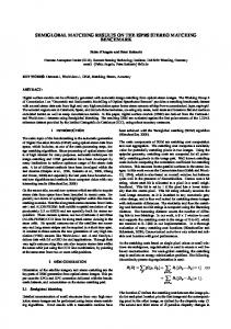
2. DATA SETUP AND PRE-PROCESSING One of the steps taken towards a multi-sensor approach was the standardization of the stereo model, i.e. the provision of imagery in epipolar orientation. Due the memory-intense SGM processing, a tiling scheme is generally required. It has to be optimized considering the available stereo coverage – depending on frame image size, flight and processing configuration. 2.1 Epipolar Rectified Imagery Straight, parallel epipolar lines are generally desired for image matching; it is a precondition in our SGM setup. Such a configuration is theoretically provided by a perfectly linear linescan. However, the actual ADS flight is non-linear due to Earth curvature and atmospheric turbulence, resulting in (perceived) distortions and curved epipolar geometry in the level-0 data, which is merely a collection of individual scan-line’s images. Therefore, the original data from all view angles are rectified to a common plane. The result is continuous geometry throughout a very long ADS strip (level-1), i.e. redundant stereo coverage for hundreds of thousands of scan-lines with piecewise straight and parallel epipolar lines (Figure 1).
The initial implementation for ADS comprises pre-processing including the required epipolar rectification, the disparity map computation based on SGM and various post processing steps to eventually provide an info cloud that is virtually error-free. The SGM core and most post-processing are carried out in disparity space, which is geometrically identical with the rectified image; it is independent from the type of sensor, and the transition from ADS to frame data processing is straightforward. For pre-processing and final projection into the info cloud, we implemented
17
International Archives of the Photogrammetry, Remote Sensing and Spatial Information Sciences, Volume XXXIX-B3, 2012 XXII ISPRS Congress, 25 August – 01 September 2012, Melbourne, Australia
For the ADS40/80, the SGM job size covers the swath width of 12000 pixels and approximately 8000 scan-lines along strip, resulting in about 100 Megapixels to be processed. This size is roughly in the order of the stereo overlap of medium and largeformat frame images, leading to similar run times and info cloud sizes for frame jobs. Examples for different sensors and flight configurations are shown in Table 1.
Figure 1. Epipolar rectification for ADS strips. Left: level-0 data with curved epipolar lines. Right: level-1 projection, resulting in piecewise straight epipolar geometry.
3. SGM AND POST PROCESSING
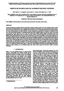
Frame epipolar lines are inherently straight (after lens distortion correction). However, images of a stereo pair are generally not located on a common plane, resulting in non-parallel epipolar lines. Aiming for processing frame stereo pairs in any orientation (including across flight strips) and also for the standardization of SGM input, we rotate frame images into the epipolar orientation and rectify them to a common plane (Figure 2).
The SGM approach is well-documented by Hirschmüller (2005, 2008); our implementation for ADS line-scanner imagery is detailed in Gehrke et al. (2010, 2011). Based on the standardization in the above-described pre-processing, the SGM core algorithm as well as most steps of the disparity post processing are sensor-agnostic and, accordingly, required only minor adaptations to process ADS and frame image jobs. Therefore, the description of our approach to disparity computation and post processing is kept brief in this context. 3.1 Disparity Computation by SGM SGM aggregates pixel-based matching costs under consideration of smoothness constraints. It approximates the theoretically desired two-dimensional, global aggregation by a number of one-dimensional cost paths for each potential disparity or, respectively, parallax. A total of 8 paths (directions every 45°) is usually considered sufficient. Using 16 paths can improve the results but increases computation time, in our current CPU implementation by about 15% in total. The minimum aggregated cost, summed from 8 or 16 directions, at each image pixel leads to the disparity map for a stereo image pair.
Figure 2. Epipolar rectification for frame imagery of arbitrary orientation. Left: original image with non-parallel epipolar lines. Right: epipolar rotation and plane rectification. 2.2 SGM Job Definition Based on the memory requirements of the SGM computation, aerial line-scanner and frame images have to be sub-divided for processing. We use tiles of up to 1024 image pixels square, with tile size and pattern adapted to the area to be processed – typically the entire stereo overlap in case of a frame image pair. The long and continuous line-scanner image strips are divided into sections that can be computed in a reasonable amount of time, say less than one hour for each individual SGM job (depending on the disparity range, see section 5 for performance numbers). A limiting factor is also the amount of data in the info cloud, so this output could be displayed and further processed by thirdparty software. All SGM job results from a single line-scanner strip can be merged seamlessly to generate a very large, geometrically and radiometrically consistent info cloud.
Sensor ADS40/80 DMC-II 140 DMC-II 230 DMC-II 250 RCD30
Stereo Overlap [%]
Swath Width [px]
Job Length [px]
Job Size [Mpx]
100 60
12,000
8,192 6,720
100 81
8,960 8,486 11,316 8,410
108 132 176 141
11,212 4,040 5,386
188 36 48
80 60 80 60 80 60 80
12,096 15,552 16,768 9,000
3.2 Outlier Elimination and Cleanup As a first step in the disparity verification, the roles of base and pair (or “left” and “right”) images in a stereo pair are swapped, and SGM is carried out both ways. Inconsistent disparities are eliminated; they indicate mismatches, which occur predominantly in occluded areas (cp. disparity maps in Figure 3). Further verification is based on the assumption that small isolated patches, which significantly differ in height (or disparity) from their neighborhood, are most likely errors. For the required segmentation, neighboring pixels with significantly different disparities are assigned to different segments. Small segments are considered outliers and removed from the disparity map. Depending on the usage of the SGM results, an optional cleanup step can be applied to remove multiple heights at the same planimetric location. This can occur within complex buildings (e.g. under balconies) or underneath trees if viewed off-nadir, and would cause undesired ambiguities in derived 2.5D products such as TINs or gridded DSMs. 3.3 Data Reduction and Thinning Considering the large amount of data (cp. Table 1), a reduction might be desired or even required. This is carried out in two ways: by a combination of 2x2 neighboring disparities into one and/or by intelligent thinning. The disparity combination also removes noise and generally increases vertical accuracy; it reduces the data by up to 75%. Thinning is based on local ranking of curvature. This ensures a globally even distribution of derived points while keeping the locally most significant ones. This allows for further data reduction, by 90-99%.
Table 1. SGM job properties for selected line scanner and frame sensors, based on Sandau et al. (2000) and Z/I Imaging (2011).
18
International Archives of the Photogrammetry, Remote Sensing and Spatial Information Sciences, Volume XXXIX-B3, 2012 XXII ISPRS Congress, 25 August – 01 September 2012, Melbourne, Australia
3.4 Info Cloud Generation
4. STEREO PAIR COMBINATION
Both high-resolution and thinned disparity maps are projected into object space, resulting in dense and thinned object point representations, respectively. Multispectral information is assigned to each individual point in these info clouds. Classification (water, low and high vegetation) based on the NDVI is integrated into the approach and can be carried out if red and NIR bands are available from the sensor. The final info cloud is output into LAS format.
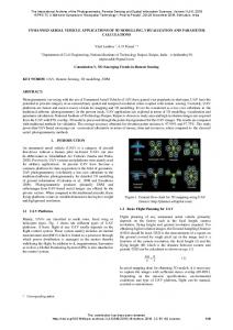
It is normally required to combine SGM results from multiple stereo views at some point in the workflow. Besides providing results for large areas, this combination allows for gap filling (occlusions) as well as consistency checks. The ADS features three panchromatic view angles that are typically used in our processing, resulting in systematic and redundant stereo coverage throughout the strip; the SGM results of which can be merged at disparity level. Frame stereo depends on the flight configuration, i.e. the image overlap along and across strip. In any case, frame SGM jobs are inherently smaller than the image size and, as opposed to the jobs along an ADS strip, they overlap. The geometry of frame-based disparity maps is dependent on the particular image and, therefore, not consistent in a frame strip. As a consequence, frame-based SGM results would have to be merged in object space. 4.1 Disparity Merge The merge of the results from different stereo angles in disparity space presumes common reference geometry, in case of the ADS the epipolar rectified nadir view. Disparities from different stereo pairs – nadir/backward and nadir/forward for the ADS – are generally scaled relative to each other. For a line-scanner, this scale can locally vary due to non-linear flight movement, which we consider for the disparity conversion based on each scan-line’s well-known orientation. Scale-corrected disparities are used to fill gaps that occur due to unavoidable occlusions in individual stereo pairs as well as for consistency checks and noise reduction by averaging. The disparity merge for ADS stereo pairs is carried out before any post processing steps, so that outlier elimination, cleanup and thinning as described in section 2 are applied to the combined disparity map. Figure 3 illustrates this merge, embedded into the ADS workflow.
Figure 3: SGM processing workflow with disparity merge. Top: ADS backward (left) and forward (right) panchromatic images. Below: color-encoded disparity maps based on nadir/backward (left) and nadir/forward image matching (right); stereo pair merge in disparity space, with most occlusions and gaps filled. Bottom: final RGB colored info cloud in true ortho view.
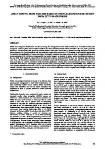
Figure 4: Merge of info clouds from individual frame stereo pairs, based on DMC-II data. Top: section from a single strip, flown West to East. Bottom left: corresponding info cloud from the adjacent strip. Bottom right: Final result, combining data from all three info clouds.
19
International Archives of the Photogrammetry, Remote Sensing and Spatial Information Sciences, Volume XXXIX-B3, 2012 XXII ISPRS Congress, 25 August – 01 September 2012, Melbourne, Australia
4.2 Info Cloud Merge
5.1 Sacramento (ADS80)
In case of airborne (non-oblique) imagery, the merge of info clouds can be carried out similar to the disparity merge, based on the rasterization of individual results as proposed by Hirschmüller (2008). With gap filling and consistency checks comparable to section 2, the final geometric result will be a gridded 2.5D DSM. A corresponding true ortho-image could be derived from the info cloud’s color data.
The Sacramento, California, data set was captured with an ADS80 for North West production in 2011. It covers the entire metro area in a GSD of 15 cm. The SGM-based image cloud was derived from all panchromatic views of the ADS, i.e. nadir/ backward and nadir/forward stereo pairs. The results of which were merged in disparity space as described in section 4.1. RGB and near-infrared color was assigned to the info cloud based on the multispectral nadir views. The RGB colored info cloud from an SGM job in Downtown Sacramento is shown in Figure 5.
Especially if the info cloud is a product in itself, it is desired to merge the three-dimensional results, which also increases point density. This idea is illustrated in Figure 4. Note that the example has been combined in a straightforward way, without geometric or radiometric adaptation.
The TIN model of the California State Capitol (Figure 5, bottom) shows a good representation of building edges, with only minor issues (e.g., above the entrance). Shadow areas next to the building and the cupola are fully and correctly covered by points, even though such areas are most challenging for our SGM implementation and image matching in general (cp., e.g., Legat, 2012). Points located on building walls and below trees were eliminated during processing.
A more sophisticated merge of info clouds should be carried out as an integrated geometric and radiometric adjustment – based on the entire information provided by the info cloud, similar to the combined geometric/radiometric point cloud matching approach used by Gehrke (2012) for ADS quality control.
5.2 Bregenz (RCD30) This small RCD30 block in Bregenz, Austria, consists of three images with a nominal GSD of 15 cm; the stereo overlap is about 60%. The data was provided by Leica Geosystems for the very initial testing of our multi-sensor SGM. Info cloud results from one of these stereo pairs are shown in Figure 6.
5. EXAMPLES FROM DIFFERENT SENSORS Our SGM implementation has been used to process very large amounts of ADS data sets, at North West Geomatics’ (North West), Leica Geosystems, their customers and other institutions. The multi-sensor extension was run with DMC/DMC-II and RCD30 frame data so far. Info cloud examples from all these sensor types are discussed in the following; Table 2 gives an overview on the data sets and performance numbers.
Figure 5: RGB colored info cloud of an ADS80 job in Downtown Sacramento (top) and enlarged TIN view of the California State Capitol (bottom).
Figure 6: RGB colored info cloud derived from RCD30 data in Bregenz, Austria (top) and enlarged TIN view (bottom).
20
International Archives of the Photogrammetry, Remote Sensing and Spatial Information Sciences, Volume XXXIX-B3, 2012 XXII ISPRS Congress, 25 August – 01 September 2012, Melbourne, Australia
Compared to the ADS result (Figure 5), the RCD30 TIN shown in Figure 6, bottom, shows a higher noise level, on both the paved ground and roof areas. This is due to the fact that there is no redundant stereo coverage in this area, which would allow for consistency checks, noise reduction and gap filling. Gaps due to occlusions cause inclined rather than vertical TIN meshes, visible at some building walls. However, such issues could easily be addressed with a flight configuration that provides more image overlap, e.g. 80%. Aside from that, the building edge representation is correct and small details are very well recognizable.
5.3 Aalen (DMC-II 140) A high-resolution block of the town of Aalen, Germany, was used for SGM verification for the DMC-II. The image overlap is approximately 60% along strip and 20% across strip, which means most areas are covered by one stereo pair and, accordingly, in a single info cloud only. An example result is shown in Figure 7. Based on the GSD of 5 cm, the SGM-derived info cloud features more than 300 points/m2 and, accordingly, contains a lot of detail – such as street lamps (Figure 7, center) –, which is especially visible when zooming all the way to the individual point level for the cars parked in front of the Z/I Imaging building (Figure 7, bottom). Similar to the RCD30 example discussed above, additional stereo coverage could be expected to reduce noise and fill gaps, e.g. at the back of the van on the left.
Figure 7: RGB colored info cloud of a DMC-II 140 stereo overlap in Aalen, Germany (top); TIN view of the Z/I Imaging building (center); and enlarged info cloud of cars parked in front of that building to illustrate the high point density (bottom).
Figure 8: Comparison of RGB (top) and FCIR (bottom) info clouds in a forest area in Georgian Bay, Canada.
21
International Archives of the Photogrammetry, Remote Sensing and Spatial Information Sciences, Volume XXXIX-B3, 2012 XXII ISPRS Congress, 25 August – 01 September 2012, Melbourne, Australia
such as high-resolution DSMs and true ortho-image mosaics, for both frame and ADS imagery.
5.4 Georgian Bay (ADS80) Located on the coast of Lake Huron’s Georgian Bay in Ontario, Canada, this block is dominated by forest. The imagery has been captured by North West in 2009 for the Ontario Ministry of Natural Resources (OMNR) in a GSD of 30 cm.
7. REFERENCES Gehrke, S., 2012. Combined Geometric/Radiometric Point Cloud Matching for Shear Analysis. Int. Arch. Phot. & Rem. Sens., Melbourne, Australia, Vol. 39, Part B1.
The resulting info clouds as shown in Figure 8 have already proven their value to OMNR for extracting forest inventory, based on the ADS’s distinct, calibrated color bands in combination with the high point density that exceeds the resolution of LiDAR data available in that area. Individual tree crowns are visible in the info cloud; the additional spectral information allows for manual extraction and/or automated classification of different tree species.
Gehrke, S., K. Morin, M. Downey, N. Boehrer, and T. Fuchs, 2010. Semi-Global Matching: An Alternative to LiDAR for DSM Generation? Int. Arch. Phot. & Rem. Sens., Calgary, AB, Vol. 38, Part B1. Gehrke, S., R. Uebbing, M. Downey, and K. Morin, 2011. Creating and Using Very High Density Point Clouds Derived from ADS Imagery. Proc. ASPRS Annual Conference, Milwaukee, WI.
5.5 SGM Performance The performance of SGM depends predominantly on the disparity range, which is determined by the terrain on one hand and sensor and imaging configuration (GSD and base to height ratio) on the other hand. This correlation can be clearly seen in the performance numbers of Table 2. GSD Sensor
[m]
Max. Disparity
Georgian Bay
0.30
104
58,700
Sacramento Aalen Bregenz
0.15 0.05 0.15
488 296 96
34,200 47,800 71,400
Data Set
ADS80 DMC-II 140 RCD30
Performance [pts/s]
Hirschmüller, H., 2005. Accurate and Efficient Stereo Processing by Semi-Global Matching and Mutual Information. Proc. IEEE Conference on CVPR, New York, New York. Hirschmüller, H., 2008. Stereo Processing by Semiglobal Matching and Mutual Information. IEEE Transactions on Pattern Analysis and Machine Intelligence, Vol. 30, No. 2, pp. 328-341. Jacobsen, K., 2011. Geometric Property of Large Format Digital Camera DMC II 140. Photogrammetriue – Fernerkundung – Geoinformation (PFG), Vol. 2011, No. 2, pp. 71-79. Legat, K., 2012. Dense Image Matching – Initial Results. EuroSDR Workshop, Vienna, Austria, http://www.ipf.tuwien.ac.at/ wm/download/12_ws_dsm_eurosdr/16_Legat_LinzExperiences. pdf.
Table 2: SGM processing job statistics for different sensors and data sets.
Sandau, R., Braunecker, B., Driescher, H., Eckardt, A., Hilbert, S., Hutton, J., Kirchhofer, W., Lithopoulos, E., Reulke, R., Wicki, S., 2000. Design Principle of the LH Systems ADS40 Airborne Digital Sensor. Int. Arch. Phot. & Rem. Sens., Amsterdam, The Netherlands, Vol. 33, Part B1, pp. 258-265.
The vast majority of time in our CPU implementation is spent in the SGM cost computation and aggregation, which is identical for ADS and frame imagery. Considering that also the pre-processing and the final ground projection are similar operations, almost identical processing times can be expected in the same terrain and with comparable imaging constellations, i.e. frame overlap with a base to height ratio similar to the (fixed) ADS stereo angles.
Z/I Imaging, 2011. Camera Comparison. Brochure, ZI Imaging.
6. CONCLUSION AND OUTLOOK The paper presents our SGM-based DSM extraction software that can be used with different types of imagery, including linescanner and frame data. The ADS implementation has been used extensively in production at North West since more than two years, and it has become part of the Leica XPro ADS ground processing software. The extensions and adaptations to frame imagery will be publicly released shortly in Intergraph’s ImageStation Automatic Elevations - Extended. The discussed results show that our SGM implementation can collect info clouds from ADS and frame data, delivering a product superior to LiDAR in geometric and spectral resolution. It can be used instead of or in combination with LiDAR for many applications; some of which have yet to be explored. An important step to be addressed in the future is the merge of info clouds. The final goal is to compute large, consistent info cloud mosaics, which also form the basis for derived products
22